EP0192014A1 - Cleaning apparatus for textile machines - Google Patents
Cleaning apparatus for textile machines Download PDFInfo
- Publication number
- EP0192014A1 EP0192014A1 EP85810068A EP85810068A EP0192014A1 EP 0192014 A1 EP0192014 A1 EP 0192014A1 EP 85810068 A EP85810068 A EP 85810068A EP 85810068 A EP85810068 A EP 85810068A EP 0192014 A1 EP0192014 A1 EP 0192014A1
- Authority
- EP
- European Patent Office
- Prior art keywords
- cleaning
- cleaning device
- textile machines
- textile
- compressed air
- Prior art date
- Legal status (The legal status is an assumption and is not a legal conclusion. Google has not performed a legal analysis and makes no representation as to the accuracy of the status listed.)
- Granted
Links
Images
Classifications
-
- D—TEXTILES; PAPER
- D01—NATURAL OR MAN-MADE THREADS OR FIBRES; SPINNING
- D01H—SPINNING OR TWISTING
- D01H11/00—Arrangements for confining or removing dust, fly or the like
- D01H11/005—Arrangements for confining or removing dust, fly or the like with blowing and/or suction devices
- D01H11/006—Arrangements for confining or removing dust, fly or the like with blowing and/or suction devices travelling along the machines
-
- D—TEXTILES; PAPER
- D03—WEAVING
- D03J—AUXILIARY WEAVING APPARATUS; WEAVERS' TOOLS; SHUTTLES
- D03J1/00—Auxiliary apparatus combined with or associated with looms
- D03J1/002—Climatic conditioning or removing lint or dust
Definitions
- the invention relates to a cleaning device for textile, in particular weaving machines.
- a cleaning device for textile in particular weaving machines.
- the flight consists primarily of fibers, which can accumulate on machine parts and on the operating floor to form larger cushions.
- Such devices can reduce the pollution of textile machines, but this does not allow targeted, intensive cleaning at places that are particularly vulnerable to flight.
- the invention enables individual cleaning programs to be carried out on the respective machine.
- the cleaning device can be used at regular intervals, for example, for cleaning parts of one or more textile machines that are particularly vulnerable to flight, with or without machine downtime.
- the cleaning device on weaving machines can for example, in the infeed area of the weft, the flight can be sucked off from thread-carrying parts.
- the warp threads of weaving machines can be continuously freed of loose fibers, which would lead to warp thread breaks in larger collections.
- a cleaning device according to the invention - without the use of personnel - can also carry out intensive cleaning operations according to a separate program, for example the suctioning off of large flight accumulations inside machines.
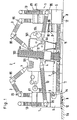
- two cleaning devices 1 work simultaneously on a weaving machine 2 containing a machine frame 101, a spanning tree 102, shafts 103 and a goods take-off roller 104 - during the article change (e.g. use of different warp and weft material for the purpose of producing a different fabric).
- the warp and fabric tree are removed from the weaving machine.
- two drivable robot arms 3, 13 are arranged as functional elements in the upper area.
- Suction nozzles 4 and blowing nozzles 4a are attached as cleaning agents.
- the lower area of the cleaning device 1 is formed by a travel drive 5.
- an electrical receiver (sensor) 6 in the lower part of the cleaning device, an electrical transmitter 7 arranged on the weaving machine receives contactlessly about the cleaning operations to be carried out. If the cleaning program is stored in electronic control means 5a of the cleaning device, a short sequence of signals is sufficient for transmission, which calls the cleaning program in device 1.
- a control center determines the route to a specific cleaning object (weaving machine) during operation.
- the cleaning device on the right in Fig. 1 is provided at the connection points 9 with couplings 10 for supply e.g. connected with compressed air and electrical current (lines 86).
- the connection of the coupling 10 of the device 1 to the connection point 9 of the weaving machine can e.g. are automatically produced by one of the robot arms 3, 13 (FIG. 5).
- suction hoses 11 are attached as further functional elements, through which dust (flight) in the vicinity of the weaving floor 5b can be suctioned off.
- Suction openings 12 are also provided on the underside of the driving unit 5 for direct suction.
- a filter kettle 71 is provided in the upper part of the cleaning device 1. This can be emptied automatically at a disposal station (collection point for the collected dust or flight) or replaced by an empty replacement filter kettle. If necessary, the device 1 can also be disposed of via a central emptying device within the company.
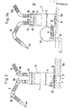
- a cleaning device 1 is located above a bottom opening 21, the cover plates 22 of which are laterally displaced.
- the contents of the filter kettle 71 in the cleaning device can be ejected downwards.
- a cleaning device 1 is moved laterally to a suction blower 23 which empties the filter kettle 71 of the cleaning device via a suction shaft 24.
- Servomotors 82 housed, of which the movement of the worms-like arms 3a, 13a equipped with support disks 52 (FIG. 5) can be controlled by means of pull cables 51.
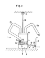
- Fig. 3 shows a cleaning device 1 with various auxiliary devices.
- Various cleaning agents e.g. Blowing or suction nozzles 4a, 14, or other tools stored for selection.
- Mechanical means e.g. rotating brushes driven by compressed air should be practical.
- the robot arm 3 removes e.g. the nozzle 4a automatically from the magazine 31.
- the supply lines (electricity and / or compressed air) 34 are arranged in FIG. 3 above the induction track 8 of the cleaning device.
- the cleaning device 1 is equipped with a guide arm 36 which can be swiveled by 74 according to arrow 92 for exact positioning relative to the weaving machine 2 indicated on the right in FIG. 3 and to which a guide profile 37 for the device 1 is attached. The guidance of the cleaning device next to the textile machine is then transferred from the guide track 8 to the positioning device 36, 37.
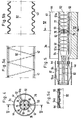
- 4 and 5 are a cross-sectional or longitudinal section through the robot arm 3 with a coupling device 32.
- the arm 3 there is an inner tube 44.
- the cables 51 serving as control cables for the movement of the arm 3 are in bores 76, the support cable 51a is guided in bores 77 of the support disks 52.
- a compressed air supply duct 44 and two air return or suction ducts 78, 79 are accommodated.
- the hose 41 is made, for example, of flexible plastic.
- a support wire 42 (FIG. 5a) can be inserted to maintain the inherent stability of the hose 41 (central axis 92).
- the hose can also be designed as a corrugated tube 43 (FIG. 5b).
- Compressed air can be applied to the coupling device 32 at the end of the arm 3a through a line 53, whereupon the flexible cylinder wall 54 bulges outwards into the position 54a shown in broken lines in FIG. the pushed-on nozzle 4a according to FIG. 3 clamps from the inside.
- the cylinder wall 54 like the hose 41, is made of flexible plastic.
- a cylindrical, perforated support jacket 55 is attached to the outside around the flexible cylinder wall 54.
- the nozzle 4a can be plugged onto this, for example. If compressed air is introduced through channel 53, the flexible W 2nd 54 lies in the form of a corrugation 54b shown in FIG. 5c from the inside against the nozzle 4a, which holds it.
- the movement-related parts for the drive and the movements of the robot arms 3, 13, 11 indicated by the arrows 95 are not all shown in detail. They are at least partially known from robot technology.
- a correspondingly designed and similarly functioning cleaning device can, for example, also be used to clean a spinning device machine can be used. With the cleaning device, certain aggregates of a textile machine can also be cleaned during operation, that is, with the textile machine running. With the cleaning device, for example, a machine can also be cleaned at specific, selected times or according to the degree of soiling.
Abstract
In einem automatisch arbeitenden Reinigungsgerät (1) für Textilbetriebe, insbesondere für Webereien, sind an einem Fahrantrieb (5) Funktionsorgane (3, 13) zur Betätigung von Reiniguangsmitteln (4, 4a) sowie Steuermittel (7, 6, 5a, 82) angeordnet, die das durch eine Spurführung (8) geleitete Gerät (1) zum Reiningungsobjekt, z.B. eine Webmaschine (2), steuern und dort programmierte Reinigungsoperationen auslösen. Dadurch lassen sich gezielte, individuelle Reinigungsoperationen an bestimmten Aggregaten der Webmaschine und/oder zu bestimmten Zeiten und/oder nach bestimmten Bedarfsmeldungen ausführen.Functional elements (3, 13) for actuating cleaning means (4, 4a) and control means (7, 6, 5a, 82) are arranged on a traction drive (5) in an automatically operating cleaning device (1) for textile companies, in particular for weaving mills. the device (1) guided by a track guidance (8) to the cleaning object, eg a weaving machine (2), control and trigger programmed cleaning operations there. In this way, targeted, individual cleaning operations can be carried out on specific units of the weaving machine and / or at specific times and / or according to specific need messages.
Description
Die Erfindung bezieht sich auf ein Reinigungsgerät für Textil-, insbesondere Webmaschinen. In Textilbetrieben mit Maschinen zur Garnherstellung oder Garnverarbeitung ist vor allem bei der Verwendung von Baumwolle eine starke Staubbildung (Flugbildung) zu beobachten. Der Flug besteht vor allem aus Fasern, welche sich an Maschinenteilen und am Betriebsboden zu grösseren Polstern ansammeln können.The invention relates to a cleaning device for textile, in particular weaving machines. In textile companies with machines for yarn production or yarn processing, a lot of dust formation (flight formation) can be observed especially when using cotton. The flight consists primarily of fibers, which can accumulate on machine parts and on the operating floor to form larger cushions.
Für eine störungsfreie Produktion ist regelmässiges Entfernen der Flugansammlungen nötig, wozu z.B. vom Bedienungspersonal geführte Reinigungsgeräte eingesetzt werden.Regular removal of the flight accumulations is necessary for trouble-free production, for which purpose e.g. cleaning devices operated by the operating personnel are used.
Es ist auch ein selbsttätiges, an der Decke des Raumes angebrachtes Reinigungsgerät bekannt (CH-PS 419 931), das in einem bestimmten, immer gleichen Arbeitszyklus über Textilmaschinen hin- und herwandert, wobei es beim Hinweg und beim Rückweg jeweils unterschiedliche Luftströmungen über den Textilmaschinen erzeugt. Durch die Umsteuerung der Strömungsrichtung der Blasluft können Flugablagerungen in toten Ecken vermieden werden. Bei anderen bekannten Reinigungsgeräten werden gleichzeitig Organe mit Blas-und Saugöffnungen eingesetzt. Die Blasorgane werden bei manchen Ausführungen zur Erweiterung ihres Aktionsbereiches hin- und hergeschwenkt.There is also known an automatic cleaning device attached to the ceiling of the room (CH-PS 419 931), which moves back and forth over textile machines in a certain, always the same working cycle, with different air flows over the textile machines on the way there and on the way back generated. By changing the direction of flow of the blown air, flight deposits in dead corners can be avoided. In other known cleaning devices, organs with blowing and suction openings are used at the same time. The blowing organs are swung back and forth in some versions to expand their range of action.
Solche Einrichtungen können zwar die Verschmutzung von Textilmaschinen reduzieren, jedoch ist damit keine gezielte, intensive Reinigung an besonders fluggefährdeten Stellen möglich.Such devices can reduce the pollution of textile machines, but this does not allow targeted, intensive cleaning at places that are particularly vulnerable to flight.
Wenn auf den Einsatz der beschriebenen Geräte in einem Textilbetrieb verzichtet wird, so muss das Bedienungspersonal von Zeit zu Zeit Reinigungsarbeiten durchführen. Solche Arbeiten erfordern grosse Kraftanstrengungen, da die Reinigungsgeräte und Reinigungsorgane von Hand geführt werden müssen und bei den oft beträchtlichen Maschinendimensionen weite Greifräume überwunden werden müssen. Bei laufenden Maschinen ist das Reinigen von Hand wegen Unfallgefahr teilweise überhaupt nicht möglich.If the described devices are not used in a textile company, the operating personnel must carry out cleaning work from time to time. Such work requires a great deal of effort, since the cleaning devices and cleaning organs have to be guided by hand and, with the often considerable machine dimensions, wide gripping spaces have to be overcome. When the machine is running, cleaning by hand is sometimes not possible at all because of the risk of an accident.
Aufgabe der Erfindung ist es, die beschriebenen Nachteile bekannter Lösungen auszuräumen. Die Erfindung ist gekennzeichnet durch
- - einen spurgeführten Fahrantrieb,
- - mindestens ein darauf angeordnetes, antreibbares Funktionsorgan zur Betätigung von Reinigungsmitteln, und
- - Steuermittel,
womit das Gerät automatisch zu bestimmten Textilmaschinen lenkbar ist und dort programmierte Reinigungsoperationen ausführen kann.The object of the invention is to overcome the disadvantages of known solutions described. The invention is characterized by
- - a track-guided drive,
- - At least one drivable functional element arranged thereon for actuating cleaning agents, and
- - tax funds,
with which the device can be steered automatically to certain textile machines and can carry out programmed cleaning operations there.
Durch die Erfindung können individuelle Reinigungsprogramme an der jeweiligen Maschine durchgeführt werden. Das Reinigungsgerät lässt sich beispielsweise für die Reinigung von besonders fluggefährdeten Teilen einer oder mehrerer Textilmaschinen mit oder ohne Maschinenstillstand in regelmässigen Abständen einsetzen. Bei der Verwendung des Reinigungsgerätes an Webmaschinen kann beispielsweise im Einlaufbereich des Schussfadens der Flug von fadenführenden Teilen abgesaugt werden. Bei einer anderen Betriebsweise können die Kettfäden von Webmaschinen kontinuierlich von losen Fasern befreit werden, die in grösseren Ansammlungen zu Kettfadenbrüchen führen würden. Durch den laufenden Einsatz eines oder mehrerer Reinigungsgeräte kann so ein höherer Betriebsnutzeffekt bei gleichzeitiger Steigerung der Gewebequalität erreicht werden.The invention enables individual cleaning programs to be carried out on the respective machine. The cleaning device can be used at regular intervals, for example, for cleaning parts of one or more textile machines that are particularly vulnerable to flight, with or without machine downtime. When using the cleaning device on weaving machines can for example, in the infeed area of the weft, the flight can be sucked off from thread-carrying parts. In another mode of operation, the warp threads of weaving machines can be continuously freed of loose fibers, which would lead to warp thread breaks in larger collections. Through the continuous use of one or more cleaning devices, a higher operational efficiency can be achieved while increasing the fabric quality.
Bei Kett- oder Artikelwechsel an Webmaschinen können auch von einem Reinigungsgerät gemäss der Erfindung -- ohne Einsatz von Personal -- nach gesondertem Programm intensive Reinigungsoperationen, beispielsweise das Absaugen von grösseren Flugansammlungen im Inneren von Maschinen, durchgeführt werden.In the event of warp or article changes on weaving machines, a cleaning device according to the invention - without the use of personnel - can also carry out intensive cleaning operations according to a separate program, for example the suctioning off of large flight accumulations inside machines.
Bei Anordnung mehrerer Funktionsorgane (z.B. Düsen) an einem Reinigungsgerät können unabhängige Reinigungsvorgänge gleichzeitig abgewickelt werden. Durch Organe im unteren Bereich des Reinigungsgerätes kann während der Fahrt der Websaalboden sauber gehalten werden.If several functional elements (e.g. nozzles) are arranged on one cleaning device, independent cleaning processes can be carried out simultaneously. Organs in the lower area of the cleaning device keep the floor of the weaving room clean while driving.
Im Gegensatz zu bekannten Re'inigungsgeräten, die über den Maschinen an gesonderten Schienen aufgehängt sind, kannbei dem erfindungsgemässen Gerät kein Flug auf die Textilmaschinen herabfallen. Durch den Wegfall gesonderten Hängeschienen können Investionskosten eingespart werden. Durch die exakte Führung der Düsen nahe am Reinigungsobjekt kann mit geringerem Luftdurchsatz gearbeitet werden. Damit können die lufttechnischen Einrichtungen kleiner als bei herkömmlichen Geräten dimensioniert werden.In contrast to known cleaning devices which are suspended above the machines on separate rails, no flight can fall onto the textile machines in the device according to the invention. By eliminating separate hanging rails, investment costs can be saved. The precise guidance of the nozzles close to the cleaning object means that less air flow can be used. This means that the ventilation systems can be dimensioned smaller than with conventional devices.
Im folgenden wird die Erfindung in einer bevorzugten Ausführungsform anhand der Figuren näher beschrieben. Es zeigen:
- Fig. 1 zwei Reinigungsgeräte an einer stillgesetzten Webmaschine,
- Fig. 2 und 2a je ein Reinigungsgerät an einer Entsorgungsstation,
- Fig. 3 ein Reinigungsgerät mit verschiedenen Hilfsvorrichtungen,
- Fig. 4 und 5 ein Ausführungsbeispiel eines Details, in Querschnitt nach Linie IV - IV und Längsschnitt nach Linie V - V, teilweise in Ansicht,
- Fig. 5a,b,c, erläutern zugehörige Einzelheiten von abgewandelten Ausführungsformen in grösserem Massstab.
- 1 two cleaning devices on a shutdown loom,
- 2 and 2a each a cleaning device at a disposal station,
- 3 shows a cleaning device with various auxiliary devices,
- 4 and 5 an embodiment of a detail, in cross section along line IV - IV and longitudinal section along line V - V, partially in view,
- 5a, b, c explain the associated details of modified embodiments on a larger scale.
In Fig. 1 arbeiten zwei Reinigungsgeräte 1 gleichzeitig an einer ein Maschinengestell 101, einen Spannbaum 102, Schäfte l03 und eine Warenabzugswalze 104 enthaltenden Webmaschine 2-während des Artikelwechsels (z.B.Einsetzen von anderem Kett- und Schussmaterial zwecks Herstellung eines anderen Gewebes). An der Webmaschine sind Kett- und Warenbaum herausgenommen. An jedem Reinigungsgerät 1 sind im oberen Bereich zwei antreibbare Roboterarme 3,13 als Funktionsorgane angeordnet. Als Reinigungsmittel sind Absaugdüsen 4 bzw. Blasdüsen 4a angebracht. Den unteren Bereich des Reinigungsgerätes 1 bildet ein Fahrantrieb 5. Mit einem elektrischen Empfänger (Sensor) 6 im Unterteil des Reinigungsgerätes werden von einem elektrischen, an der Webmaschine angeordneten Sender 7 berührungslos Instuktionen über die durchzuführenden Reinigungsoperationen entgegengenommen. Wenn das Reinigungsprogramm in elektronischen Steuermitteln 5a des Reinigungsgerätes gespeichert ist, genügt zur Uebermittlung eine kurze Folge von Signalen, womit das Reinigungsprogramm im Gerät 1 aufgerufen wird.In Fig. 1, two
Im Boden 5b der Weberei ist eine Induktionsspur 8 eingelassen, mit der die Reinigungsgeräte 1 durch den Betrieb geführt werden. Den Weg zu einem bestimmten Reinigungsobjekt (Webmaschine) im Betrieb bestimmt eine Steuerzentrale.In the
Das in Fig. 1 rechte Reinigungsgerät ist an den Anschlussstellen 9 mit Kupplungen 10 zur Versorgung z.B. mit Druckluft und elektrischem Strom (Leitungen 86) angeschlossen. Die Verbindung der Kupplung 10 des Gerätes 1 mit der Anschlussstelle 9 der Webmaschine kann z.B. durch einen der Roboterarme 3,13 automatisch hergestellt werden (Fig. 5). Unten an den Reinigungsgeräten 1 sind als weitere Funktionsorgane Absaugschläuche 11 angebracht, durch die Staub (Flug) in der Nähe des Websaalbodens 5b abgesaugt werden kann. Auch sind Saugöffnungen 12 an der Unterseite der Fahreinheit 5 zur direkten Absaugung angebracht.The cleaning device on the right in Fig. 1 is provided at the connection points 9 with
Im Oberteil des Reinigungsgerätes 1 ist ein Filterkessel 71 vorgesehen. Dieser kann an einer Entsorgungsstation-(Sammelstelle für den eingesammelten Staub bzw. Flug) automatisch geleert oder durch einen leeren Ersatzfilterkessel ersetzt werden. Gegebenenfalls kann das Gerät 1 auch über eine zentrale entleerungseinrichtung innerhalb des Betriebes entsorgt werden.A
Bei Fig. 2 befindet sich ein Reinigungsgerät 1 über einer Bodenöffnung 21, deren Abdeckplatten 22 seitlich verschoben sind. Der Inhalt des Filterkessels 71 im Reinigungsgerät kann nach unten ausgeworfen werden.2, a
Bei Fig. 2a ist ein Reinigungsgerät 1 seitlich an ein Sauggebläse 23 herangefahren, welches über einen Absaugschacht 24 den Filterkessel 71 des Reinigungsgerätes entleert. In einem oberen Teil 81 des Gerätes 1 sind Servomotoren 82 untergebracht, von denen die Bewegung der mit Stützscheiben 52 (Fig. 5) ausgestatteten, wurmartig beweglichen Arme 3a,13a mittels Zugseilen 51 gesteuert werden kann.2a, a
Fig. 3 zeigt ein Reinigungsgerät 1 mit verschiedenen Hilfvorrichtungen. In einem Aufaahmemagazin 31 sind verschiedene Reinigungsmittel, z.B. Blas- bzw. Saugdüsen 4a,14, oder andere Werkzeuge zur Auswahl gelagert. Für bestimmte Reinigungsarbeiten können auch mechanische Mittel, z.B. mit Durckluft angetriebene rotierende Bürsten, zweckmässig sein. Mit einer Kupplungsvorrichtung 32 entnimmt der Roboterarm 3 z.B. die Düse 4a selbsttätig aus dem Magazin 31. Die Versorgungsleitungen (Strom und/ oder Druckluft) 34 sind in Fig. 3 über der Induktionsspur 8 des Reinigungsgerätes angeordnet.Fig. 3 shows a
Das Reinigungsgerät 1 ist mit einem um 74 gemäss Pfeil 92 schwenkbaren Führungsarm 36 zum exakten Positionieren relativ zur rechts in Fig. 3 angedeuteten Webmaschine 2 ausgestattet, an der ein Leitprofil 37 für das Gerät 1 angebracht ist. Die Führung des Reinigungsgerätes neben der Textilmaschine wird dann von der Leitspur 8 an die Positioniervorrichtung 36,37 übergeben.The
Fig. 4 und 5 sind ein Quer- bzw. Längsschnitt durch den Roboterarm 3 mit einer Kupplungsvorrichtung 32. In Arm 3 befindet sich ein innerer-Schlauch 44. Dieser enthält aufeinandergesetzte, tellerförmige, mit im wesentlichen - ovalem Querschnitt versehene Stützscheiben 52, die durch Seilzüge 51 und ein zentrales Stützseil 51a zusammengehalten werden. Die als Steuerseile für die Bewegung des Armes 3 dienenden Seilzüge 51 sind in Bohrungen 76, das Stützseil 51a ist in Bohrungen 77 der Stützscheiben 52 geführt. In dem Schlauch 41 sind ein Druckluft-Zuführungskanal 44 und zwei Luftrückführungs- bzw. -saugkanäle 78,79 untergebracht.4 and 5 are a cross-sectional or longitudinal section through the
Der Schlauch 41 besteht z.B. aus flexiblem Kunststoff. Zur Erhaltung der Eigenstabilität des Schlauches 41 (Mittelachse 92) kann ein Stützdraht 42 (Fig. 5a) eingelegt sein. Der Schlauch kann auch als Wellrohr 43 (Fig. 5b) ausgebildet sein.The
Die Kupplungsvorrichtung 32 am Ende des Armes 3a kann durch eine Leitung 53 mit Druckluft beaufschlagt werden, worauf sich die flexible Zylinderwand 54 nach aussen in die in Fig. 5 strichpunktiert dargestellte Position 54a wölbt und dadurch z.B. die aufgeschobene Düse 4a entsprechend Fig. 3 von innen festklemmt. Die Zylinderwand 54 besteht ebenso wie der Schlauch 41 aus flexiblem Kunststoff.Compressed air can be applied to the
Bei der Ausführungsvariante der Kupplungsvorrichtung gemäss Fig. 5c ist aussen um die flexible Zylinderwand 54 herum ein zylindrischer,gelochter Stützmantel 55 befestigt. Auf diesen kann z.B. die Düse 4a aufgesteckt werden. Wenn durch Kanal 53 Druckluft eingeleitet wird, legt sich die flexible W2.nd 54 in Form einer in Fig. 5c dargestellten Wellung 54b von innen gegen die Düse 4a, wodurch diese gehalten wird.In the embodiment variant of the coupling device according to FIG. 5c, a cylindrical, perforated
Zur Fixierung der Reinigungsmittel oder anderer Vorsätze (Düsen) am Ende des Roboterarmes 3 muss nur ein einziges Ventil im Innern des Reinigungsgerätes 1 geöffnet werden, das die Druckluftzufuhr bei 53 zur Kupplungsvorrichtung 32 erlaubt.To fix the cleaning agents or other attachments (nozzles) at the end of the
Die bewegungstechnischen Teile für den Antrieb und die durch die Pfeile 95 angedeuteten Bewegungen der Roboterarme 3,13, 11 sind im Einzelnen nicht sämtlich dargestellt. Sie sind aus der Robotertechnik mindestens teilweise bekannt. Ein entsprechend ausgebildetes und ähnlich funktionierendes Reinigungsgerät kann z.B. auch zur Reinigung einer Spinnmaschine verwendet werden. Mit dem Reinigungsgerät können bestimmte Aggregate einer Textilmaschine auch während des Betriebes, also bei laufender Textilmaschine gereinigt werden. Mit dem Reinigungsgerät kann z.B. auch eine Maschine zu bestimmten, ausgewählten oder dem Verschmutzungsgrad entsprechenden Zeiten gereinigt werden.The movement-related parts for the drive and the movements of the
Claims (5)
womit das Gerät (1) automatisch zu bestimmten Textilmaschinen (2) lenkbar ist und dort programmierte Reinigungsoperationen ausführen kann.1. Cleaning device for textile machines, characterized by
with which the device (1) can be steered automatically to certain textile machines (2) and can carry out programmed cleaning operations there.
Priority Applications (4)
| Application Number | Priority Date | Filing Date | Title |
|---|---|---|---|
| DE8585810068T DE3566687D1 (en) | 1985-02-20 | 1985-02-20 | Cleaning apparatus for textile machines |
| EP85810068A EP0192014B1 (en) | 1985-02-20 | 1985-02-20 | Cleaning apparatus for textile machines |
| US06/825,135 US4655258A (en) | 1985-02-20 | 1986-01-31 | Cleaning apparatus for textile machine |
| JP61033116A JPS61194257A (en) | 1985-02-20 | 1986-02-19 | Cleaning apparatus for fabric machine |
Applications Claiming Priority (1)
| Application Number | Priority Date | Filing Date | Title |
|---|---|---|---|
| EP85810068A EP0192014B1 (en) | 1985-02-20 | 1985-02-20 | Cleaning apparatus for textile machines |
Publications (2)
| Publication Number | Publication Date |
|---|---|
| EP0192014A1 true EP0192014A1 (en) | 1986-08-27 |
| EP0192014B1 EP0192014B1 (en) | 1988-12-07 |
Family
ID=8194629
Family Applications (1)
| Application Number | Title | Priority Date | Filing Date |
|---|---|---|---|
| EP85810068A Expired EP0192014B1 (en) | 1985-02-20 | 1985-02-20 | Cleaning apparatus for textile machines |
Country Status (4)
| Country | Link |
|---|---|
| US (1) | US4655258A (en) |
| EP (1) | EP0192014B1 (en) |
| JP (1) | JPS61194257A (en) |
| DE (1) | DE3566687D1 (en) |
Cited By (11)
| Publication number | Priority date | Publication date | Assignee | Title |
|---|---|---|---|---|
| EP0259622A1 (en) * | 1986-08-22 | 1988-03-16 | Maschinenfabrik Rieter Ag | Method for cleaning a textile machine having multiple working positions |
| EP0291485A1 (en) * | 1987-05-12 | 1988-11-17 | Picanol N.V. | Device for removing waste products from textile machines |
| EP0311169A1 (en) * | 1987-10-09 | 1989-04-12 | Picanol N.V. | Method for positioning of auxiliary mechanisms for weaving machines, and a device which uses this method |
| EP0394885A1 (en) * | 1989-04-24 | 1990-10-31 | Sohler Airtex Gmbh | Mobile cleaning and operating device for textile machinery |
| EP0421970A1 (en) * | 1989-10-04 | 1991-04-10 | Picanol N.V. | Method and device for collecting dust and waste in weaving machines |
| EP0467159A1 (en) * | 1990-07-20 | 1992-01-22 | Maschinenfabrik Rieter Ag | Device for automatic splicing or piecing of a yarn and procedure for cleaning of a spinning machine |
| EP0539972A1 (en) * | 1991-10-29 | 1993-05-05 | SOHLER AIRTEX GmbH | Mobile cleaning device |
| EP0620300A1 (en) * | 1993-04-16 | 1994-10-19 | Sohler Airtex Gmbh | Cleaning device |
| EP0676494A1 (en) * | 1994-04-07 | 1995-10-11 | Lindauer Dornier Gesellschaft M.B.H | Device for diminishing lint in looms |
| EP0753612A1 (en) * | 1995-07-14 | 1997-01-15 | Rieter Ingolstadt Spinnereimaschinenbau AG | Manual suction apparatus for the machine cleaning |
| WO2012046055A3 (en) * | 2010-10-06 | 2013-03-28 | Ulster Carpet Mills (Holdings) Limited | Oiling and cleaning apparatus |
Families Citing this family (9)
| Publication number | Priority date | Publication date | Assignee | Title |
|---|---|---|---|---|
| DE3634474A1 (en) * | 1986-10-09 | 1988-04-14 | Zinser Textilmaschinen Gmbh | DEVICE FOR GUIDING AN OPERATOR ALONG A SPINNING MACHINE |
| IT1208234B (en) * | 1987-01-23 | 1989-06-12 | M P Meccanica Di Precisione Sa | EMPTY AND FULL BINS IN AND FROM MACHINES PROGRAMMABLE ROBOT OF TYPE WINDING MACHINES AND FROM AND IN RESPECTIVE DATA AND OR REMOTE CONTROLLED FOR THE DEAR LOADING AND RACKING WAREHOUSES AND THE AUTOMATIC UNLOADING OF THE BOILERS |
| DE8903472U1 (en) * | 1989-03-20 | 1989-05-03 | Sohler Airtex Gmbh, 7988 Wangen, De | |
| US6922867B1 (en) * | 2001-08-08 | 2005-08-02 | Lam Research Corporation | Two position robot design for FOUP purge |
| US20060218680A1 (en) * | 2005-03-28 | 2006-09-28 | Bailey Andrew D Iii | Apparatus for servicing a plasma processing system with a robot |
| US20100037819A1 (en) * | 2008-08-14 | 2010-02-18 | Snu R&Db Foundation | Device for positioning nano materials |
| CN104911763B (en) * | 2015-06-15 | 2017-04-05 | 兴化市汤氏纺机制造有限公司 | A kind of textile machine efficiently aids in rewinding apparatus for work |
| CN110373755A (en) * | 2019-07-29 | 2019-10-25 | 南通灵敏环保设备有限公司 | A kind of blowing/absorbing cleaning machine of non-percussion formula reversing mechanism |
| CN114318601B (en) * | 2021-12-02 | 2023-12-01 | 浙江云泰纺织有限公司 | High-efficient cleaning equipment of spinning workshop fly |
Citations (5)
| Publication number | Priority date | Publication date | Assignee | Title |
|---|---|---|---|---|
| CH396715A (en) * | 1959-09-17 | 1965-07-31 | Jacobi E & Co Kg | Mobile cleaning system for textile machines, in particular for spinning machines |
| FR1427823A (en) * | 1964-12-18 | 1966-02-11 | Parks Cramer Co | Air pneumatic mobile cleaning device, in particular for loom installations |
| CH419931A (en) * | 1964-12-03 | 1966-08-31 | Sulzer Ag | Blow-off fan device for textile machines |
| FR2310428A1 (en) * | 1975-05-07 | 1976-12-03 | Jacobi E & Co Kg | CLEANING DEVICE FOR TEXTILE MACHINES INCLUDING A THREAD TIE-TIE MACHINE |
| FR2396107A1 (en) * | 1977-07-01 | 1979-01-26 | Alsacienne Constr Meca | Automatic cleaning and piecing-up carriages - for yarn spinning machines with both functions performed from a single carriage |
Family Cites Families (5)
| Publication number | Priority date | Publication date | Assignee | Title |
|---|---|---|---|---|
| US3525117A (en) * | 1966-04-28 | 1970-08-25 | Eaton Yale & Towne | Apparatus for cleaning looms |
| US3991433A (en) * | 1973-03-22 | 1976-11-16 | Cirino John F | Blower equipment for roll-over car wash |
| US3945081A (en) * | 1974-03-27 | 1976-03-23 | American Chain & Cable Company, Inc. | Loom cleaner |
| CH624999A5 (en) * | 1977-11-17 | 1981-08-31 | Sulzer Ag | |
| SU717177A1 (en) * | 1977-12-23 | 1980-02-25 | Центральное Проектно-Конструкторское И Технологическое Бюро Текстильной Промышленности | Loom cleaning arrangement |
-
1985
- 1985-02-20 DE DE8585810068T patent/DE3566687D1/en not_active Expired
- 1985-02-20 EP EP85810068A patent/EP0192014B1/en not_active Expired
-
1986
- 1986-01-31 US US06/825,135 patent/US4655258A/en not_active Expired - Fee Related
- 1986-02-19 JP JP61033116A patent/JPS61194257A/en active Pending
Patent Citations (5)
| Publication number | Priority date | Publication date | Assignee | Title |
|---|---|---|---|---|
| CH396715A (en) * | 1959-09-17 | 1965-07-31 | Jacobi E & Co Kg | Mobile cleaning system for textile machines, in particular for spinning machines |
| CH419931A (en) * | 1964-12-03 | 1966-08-31 | Sulzer Ag | Blow-off fan device for textile machines |
| FR1427823A (en) * | 1964-12-18 | 1966-02-11 | Parks Cramer Co | Air pneumatic mobile cleaning device, in particular for loom installations |
| FR2310428A1 (en) * | 1975-05-07 | 1976-12-03 | Jacobi E & Co Kg | CLEANING DEVICE FOR TEXTILE MACHINES INCLUDING A THREAD TIE-TIE MACHINE |
| FR2396107A1 (en) * | 1977-07-01 | 1979-01-26 | Alsacienne Constr Meca | Automatic cleaning and piecing-up carriages - for yarn spinning machines with both functions performed from a single carriage |
Cited By (17)
| Publication number | Priority date | Publication date | Assignee | Title |
|---|---|---|---|---|
| EP0259622A1 (en) * | 1986-08-22 | 1988-03-16 | Maschinenfabrik Rieter Ag | Method for cleaning a textile machine having multiple working positions |
| EP0291485A1 (en) * | 1987-05-12 | 1988-11-17 | Picanol N.V. | Device for removing waste products from textile machines |
| BE1000552A4 (en) * | 1987-05-12 | 1989-01-31 | Picanol Nv | Device for the disposal of waste products in textile machinery. |
| US4869296A (en) * | 1987-05-12 | 1989-09-26 | Picanol N.V. | Device for removing waste products from textile machines |
| EP0311169A1 (en) * | 1987-10-09 | 1989-04-12 | Picanol N.V. | Method for positioning of auxiliary mechanisms for weaving machines, and a device which uses this method |
| BE1000987A3 (en) * | 1987-10-09 | 1989-05-30 | Picanol Nv | Method for positioning aid elements in looms and device applying this process. |
| EP0394885A1 (en) * | 1989-04-24 | 1990-10-31 | Sohler Airtex Gmbh | Mobile cleaning and operating device for textile machinery |
| US5040570A (en) * | 1989-10-04 | 1991-08-20 | Picanol N.V. | Collecting dust and selvage waste ribbon in weaving machines onto a winding spool |
| EP0421970A1 (en) * | 1989-10-04 | 1991-04-10 | Picanol N.V. | Method and device for collecting dust and waste in weaving machines |
| BE1003533A3 (en) * | 1989-10-04 | 1992-04-14 | Picanol Nv | Method and device for collecting dust and waste of looms. |
| EP0467159A1 (en) * | 1990-07-20 | 1992-01-22 | Maschinenfabrik Rieter Ag | Device for automatic splicing or piecing of a yarn and procedure for cleaning of a spinning machine |
| EP0539972A1 (en) * | 1991-10-29 | 1993-05-05 | SOHLER AIRTEX GmbH | Mobile cleaning device |
| EP0620300A1 (en) * | 1993-04-16 | 1994-10-19 | Sohler Airtex Gmbh | Cleaning device |
| EP0676494A1 (en) * | 1994-04-07 | 1995-10-11 | Lindauer Dornier Gesellschaft M.B.H | Device for diminishing lint in looms |
| EP0753612A1 (en) * | 1995-07-14 | 1997-01-15 | Rieter Ingolstadt Spinnereimaschinenbau AG | Manual suction apparatus for the machine cleaning |
| US5720075A (en) * | 1995-07-14 | 1998-02-24 | Rieter Ingolstadt Spinnereimaschinenbau Ag | Manual suction device for textile machine cleaning |
| WO2012046055A3 (en) * | 2010-10-06 | 2013-03-28 | Ulster Carpet Mills (Holdings) Limited | Oiling and cleaning apparatus |
Also Published As
| Publication number | Publication date |
|---|---|
| US4655258A (en) | 1987-04-07 |
| DE3566687D1 (en) | 1989-01-12 |
| EP0192014B1 (en) | 1988-12-07 |
| JPS61194257A (en) | 1986-08-28 |
Similar Documents
| Publication | Publication Date | Title |
|---|---|---|
| EP0192014B1 (en) | Cleaning apparatus for textile machines | |
| DE2613180C2 (en) | Open-end spinning machine with a large number of spinning units and with at least one maintenance device | |
| DE2658752C2 (en) | Open-end spinning machine with means for taking up and removing separated impurities | |
| EP0259622B1 (en) | Method for cleaning a textile machine having multiple working positions | |
| EP0467159A1 (en) | Device for automatic splicing or piecing of a yarn and procedure for cleaning of a spinning machine | |
| DE1252870C2 (en) | DRIVING CLEANING DEVICE FOR THE REMOVAL OF THE GASER FLIGHT, etc. OF MACHINE PARTS AND THE FLOOR IN TEXTILE MACHINE SHELVES | |
| DE2518522A1 (en) | COLORABLE PNEUMATIC DEVICE FOR SUCTION AND BLOW-OFF OF FIBER FLOW IN TEXTILE MACHINERY | |
| DE2919768A1 (en) | DEVICE FOR DEDUSTING A DISHWASHER | |
| DE2815188C3 (en) | Device that can be moved on rails for pneumatic blow-off and suction of fluff in spinning, twisting and weaving machines | |
| CH669404A5 (en) | ||
| DE2339880A1 (en) | PNEUMATIC CLEANING SYSTEM OF THE DRAWING SYSTEMS IN SPINNING AND SPINNING MACHINES | |
| DE10022734A1 (en) | Open-end spinner servicing unit has a blower jet at the drive cone of the sliver insertion arm where the compressed air flow is divided by inner cone teeth for effective cleaning of the soiled zones of the sliver loosening roller | |
| DE3640001C2 (en) | OE spinning machine | |
| DE3891430C2 (en) | Cleaner for spinning machine | |
| EP0534077A1 (en) | Conveyor device | |
| DE4131525A1 (en) | Bobbin winder assembly cleaner - has common under pressure channel to remove dust from walls and winders while usable fibres are retained | |
| DE4001007C2 (en) | ||
| DE2129563A1 (en) | Travelling cleaner for textile machine - cleaner also carries broken thread knotter | |
| DE19527724A1 (en) | Rotor spinner maintenance unit | |
| DE4406756C2 (en) | Ventilation system with traveling cleaner | |
| CH664583A5 (en) | LAENGS TEXTILE MACHINES MOVABLE CLEANING DEVICE. | |
| EP0815302B1 (en) | Moving cleaner | |
| DE1265016C2 (en) | MOVABLE CLEANING DEVICE FOR SPINNING MACHINES AND THE like. | |
| DE1535066C3 (en) | Cleaning device for spinning machines | |
| DE2530735C2 (en) | Cleaning device in a spinning or twisting machine |
Legal Events
| Date | Code | Title | Description |
|---|---|---|---|
| PUAI | Public reference made under article 153(3) epc to a published international application that has entered the european phase |
Free format text: ORIGINAL CODE: 0009012 |
|
| 17P | Request for examination filed |
Effective date: 19850222 |
|
| AK | Designated contracting states |
Kind code of ref document: A1 Designated state(s): AT BE CH DE FR GB IT LI LU NL SE |
|
| RBV | Designated contracting states (corrected) |
Designated state(s): BE CH DE FR IT LI |
|
| 17Q | First examination report despatched |
Effective date: 19870126 |
|
| ITF | It: translation for a ep patent filed |
Owner name: ING. ZINI MARANESI & C. S.R.L. |
|
| GRAA | (expected) grant |
Free format text: ORIGINAL CODE: 0009210 |
|
| AK | Designated contracting states |
Kind code of ref document: B1 Designated state(s): BE CH DE FR IT LI |
|
| REF | Corresponds to: |
Ref document number: 3566687 Country of ref document: DE Date of ref document: 19890112 |
|
| PLBI | Opposition filed |
Free format text: ORIGINAL CODE: 0009260 |
|
| ET | Fr: translation filed | ||
| 26 | Opposition filed |
Opponent name: REIS GMBH & CO. MASCHINENFABRIK Effective date: 19890222 |
|
| PLBI | Opposition filed |
Free format text: ORIGINAL CODE: 0009260 |
|
| 26 | Opposition filed |
Opponent name: SOHLER AIRTEX GMBH Effective date: 19890907 Opponent name: WAGNER FOERDERTECHNIK GMBH & CO KG Effective date: 19890907 Opponent name: REIS GMBH & CO. MASCHINENFABRIK Effective date: 19890222 |
|
| PGFP | Annual fee paid to national office [announced via postgrant information from national office to epo] |
Ref country code: FR Payment date: 19910212 Year of fee payment: 7 |
|
| PGFP | Annual fee paid to national office [announced via postgrant information from national office to epo] |
Ref country code: CH Payment date: 19910227 Year of fee payment: 7 |
|
| ITTA | It: last paid annual fee | ||
| PGFP | Annual fee paid to national office [announced via postgrant information from national office to epo] |
Ref country code: DE Payment date: 19910328 Year of fee payment: 7 |
|
| PGFP | Annual fee paid to national office [announced via postgrant information from national office to epo] |
Ref country code: BE Payment date: 19910403 Year of fee payment: 7 |
|
| RDAG | Patent revoked |
Free format text: ORIGINAL CODE: 0009271 |
|
| STAA | Information on the status of an ep patent application or granted ep patent |
Free format text: STATUS: PATENT REVOKED |
|
| 27W | Patent revoked |
Effective date: 19911021 |
|
| REG | Reference to a national code |
Ref country code: CH Ref legal event code: PL |
|
| BERE | Be: lapsed |
Owner name: GEBRUDER SULZER A.G. Effective date: 19920228 |
|
| PLAB | Opposition data, opponent's data or that of the opponent's representative modified |
Free format text: ORIGINAL CODE: 0009299OPPO |