EP0192012B1 - Machines pour enrober uniformément en continu des produits de confiserie - Google Patents
Machines pour enrober uniformément en continu des produits de confiserie Download PDFInfo
- Publication number
- EP0192012B1 EP0192012B1 EP85430045A EP85430045A EP0192012B1 EP 0192012 B1 EP0192012 B1 EP 0192012B1 EP 85430045 A EP85430045 A EP 85430045A EP 85430045 A EP85430045 A EP 85430045A EP 0192012 B1 EP0192012 B1 EP 0192012B1
- Authority
- EP
- European Patent Office
- Prior art keywords
- trough
- brush
- brushes
- products
- machine according
- Prior art date
- Legal status (The legal status is an assumption and is not a legal conclusion. Google has not performed a legal analysis and makes no representation as to the accuracy of the status listed.)
- Expired
Links
Images


Classifications
-
- A—HUMAN NECESSITIES
- A23—FOODS OR FOODSTUFFS; TREATMENT THEREOF, NOT COVERED BY OTHER CLASSES
- A23G—COCOA; COCOA PRODUCTS, e.g. CHOCOLATE; SUBSTITUTES FOR COCOA OR COCOA PRODUCTS; CONFECTIONERY; CHEWING GUM; ICE-CREAM; PREPARATION THEREOF
- A23G3/00—Sweetmeats; Confectionery; Marzipan; Coated or filled products
- A23G3/34—Sweetmeats, confectionery or marzipan; Processes for the preparation thereof
- A23G3/36—Sweetmeats, confectionery or marzipan; Processes for the preparation thereof characterised by the composition containing organic or inorganic compounds
- A23G3/48—Sweetmeats, confectionery or marzipan; Processes for the preparation thereof characterised by the composition containing organic or inorganic compounds containing plants or parts thereof, e.g. fruits, seeds, extracts
-
- A—HUMAN NECESSITIES
- A21—BAKING; EDIBLE DOUGHS
- A21C—MACHINES OR EQUIPMENT FOR MAKING OR PROCESSING DOUGHS; HANDLING BAKED ARTICLES MADE FROM DOUGH
- A21C15/00—Apparatus for handling baked articles
- A21C15/002—Apparatus for spreading granular material on, or sweeping or coating the surface of baked articles
-
- A—HUMAN NECESSITIES
- A23—FOODS OR FOODSTUFFS; TREATMENT THEREOF, NOT COVERED BY OTHER CLASSES
- A23G—COCOA; COCOA PRODUCTS, e.g. CHOCOLATE; SUBSTITUTES FOR COCOA OR COCOA PRODUCTS; CONFECTIONERY; CHEWING GUM; ICE-CREAM; PREPARATION THEREOF
- A23G3/00—Sweetmeats; Confectionery; Marzipan; Coated or filled products
- A23G3/02—Apparatus specially adapted for manufacture or treatment of sweetmeats or confectionery; Accessories therefor
- A23G3/20—Apparatus for coating or filling sweetmeats or confectionery
- A23G3/2076—Apparatus for coating with powders or granules, e.g. sprinkling
-
- A—HUMAN NECESSITIES
- A23—FOODS OR FOODSTUFFS; TREATMENT THEREOF, NOT COVERED BY OTHER CLASSES
- A23P—SHAPING OR WORKING OF FOODSTUFFS, NOT FULLY COVERED BY A SINGLE OTHER SUBCLASS
- A23P20/00—Coating of foodstuffs; Coatings therefor; Making laminated, multi-layered, stuffed or hollow foodstuffs
- A23P20/10—Coating with edible coatings, e.g. with oils or fats
- A23P20/12—Apparatus or processes for applying powders or particles to foodstuffs, e.g. for breading; Such apparatus combined with means for pre-moistening or battering
Definitions
- the present invention relates to machines for uniformly coating, continuously, confectionery products comprising a solid, or gelatinous, or pasty core wrapped in one or more uniform layers, of one or more liquid and / or pulverulent products by example candies, aperitif cookies, popped cereals etc.
- the coating layers must be uniform over the entire periphery of the core. Do not crush or break the soft pits. Avoid the nuclei sticking together.
- the coating operations are carried out in a hemispherical or cylindrical tank or container which is rotated around its axis at relatively slow speed and which is designated in the trade by the name of turbine.
- a certain quantity of the product to be coated is placed in the tank, for example gelatin cores and one or more liquids, colored or not, which are uniformly impregnated with gelatin cores and then poured into the tank, while it is rotating. powdered sugar that sticks to the moistened periphery of the cores to form a uniform coating.
- the nuclei rotate on themselves, so that the liquid and then the sugar particles are distributed evenly around the periphery of each nucleus.
- This technique is well developed and it allows a very uniform coating to be obtained, without altering products such as relatively fragile gelatin cores.
- this technique has the disadvantage of being essentially discontinuous.
- appetizer cookies are made by extruding dough through a die after which the dough pieces are moistened with a liquid and then sprinkled with salt, sugar or spices.
- Patent G. B. A. 856 763 (The City Baker ⁇ es) describes an apparatus for coating sugar confectionery products which is composed of an Archimedes screw rotating in a trapezoidal trough.
- the screw is made up of rods which are installed radially on a shaft and which carry helically wound wires.
- U.S. Patent 1,893,672 (L. G. James et al.) Describes a machine for making candy which includes a helical brush rotating in an oscillating trough having a perforated bottom.
- the combined action of the brush and the oscillating trough is used to remove excess starch.
- This machine has a rotating cylindrical screen that rotates inside a trough.
- the machine has a worm screw internal to the screen and external screws integral with the screen.
- the object of the invention is to provide machines for continuously and uniformly coating confectionery products comprising a solid, gelatinous or pasty core coated in a liquid and / or pulverulent product.
- a machine according to the invention is of the known type comprising a fixed, substantially horizontal chute, an endless screw which is rotated in this chute and means for introducing into the chute the cores to be coated and liquid and / or pulverulent products. .
- the object of the invention is achieved by means of a machine which comprises one or more helical brushes which are composed of bristles implanted radially in a helix on one or two drive shafts which are driven in rotation in said chute at a speed less than 100 revolutions / minute and said chute has the shape of a trough which is open upwards, which has a height greater than the diameter of said brushes and which has a cylindrical bottom which envelops said brushes in the part located below said drive shafts.
- a machine comprises two helical brushes of the same diameter composed of bristles implanted radially in a helix on two parallel drive shafts which are rotated in opposite directions to one another and such that the bristles of the two brushes move from bottom to top in the central part of the trough.
- the invention results in the continuous coating of products such as candies, aperitif biscuits or other similar products requiring coating or dusting operations.
- the method according to the invention makes it possible to construct continuous automated installations and to reduce handling and manpower, therefore the cost of manufacturing.
- the coating is as uniform as that of the products produced batchwise in the rotating tanks called turbines which are commonly used today.
- the products being coated form between each pair of threads of the helical brush, a small package which rotates continuously on itself in a small space and, at the same time, each core also rotates on itself inside the package, so that the impregnation of the nuclei by a liquid and then by solid particles is distributed uniformly over the entire periphery of each nucleus.
- the rotation of the core bundles and the cores inside the bundles is due to the push of the brush bristles on the cores.
- these bristles are flexible, this push does not deteriorate the nuclei and does not deform them even in the case where they are soft gelled or pasty nuclei.
- the bottom of the trough is cylindrical and the bristles of the brush rub against the walls of the trough, which has the effect of sweeping them and preventing deposits from adhering to them.
- a machine according to the invention can be used for coating all kinds of products, for example for coating almonds, hazelnuts or peanuts.
- a fixing liquid for example a liquid based on alginate or oil, and then we sprinkle with sugar or salt.
- the machines according to the invention comprising two helical brushes of opposite pitch, mounted on two parallel shafts, have the advantage that the products being coated accumulate between the two brushes where an intense stirring effect of said products occurs. without these coming into contact with the walls of the trough.
- the machines according to the invention comprising one or two curved side walls which extend the semi-cylindrical bottom of the trough above the horizontal plane in which the axis or axes of the drive shafts is located, have the advantage of eliminating the need to mount these shafts on bearings and avoid the phenomena of self-saturation of the machine in the case where the flow rate of product to be coated is greater than the transport capacity of the machine.
- the machines according to the invention comprising one or two drive shafts each carrying bristles which are located on said shaft along two parallel and interposed propellers, make it possible to increase the speed of the machine without increasing the speed of rotation.
- the machines according to the invention equipped with a spraying boom or any other equivalent means for dispensing a cleaning liquid are self-cleaning machines which allow rapid switching from the manufacture of a product to that of another product.
- the various figures represent machines intended for continuously coating solid products, with liquids such as a sweet syrup, honey or oil and / or with pulverulent products such as salt, sugar, cocoa in conditions such that the solid products are uniformly coated with the liquid and / or pulverulent products.
- liquids such as a sweet syrup, honey or oil
- pulverulent products such as salt, sugar, cocoa
- the machines according to the invention are used in particular in the manufacture of confectionery products such as candies, savory or sweet cookies, dried fruit coated with sugar or salt, and in general, any product comprising a solid, pasty core or gelatinous which must be uniformly moistened and / or uniformly covered with one or more layers of a pulverulent product.
- the machines according to the invention can also be used to manufacture products which require a cooking step, for example popped cereals of the popcorn type or the like.
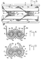
- Figures 1 and 2 show a machine which comprises a chute in the shape of a straight trough 1, composed of a cylindrical bottom 2, in the shape of a semicircle extended by two side walls 3d and 3g, which are vertical in the example represented.
- Level 1 is open at the top and at the front end.
- a machine further comprises an endless screw which is composed of a drive shaft 4 and a helical brush 5, constituted by flexible bristles, for example horsehair or synthetic fibers which are implanted helically on the shaft 4.
- the two ends of the shaft 4 are supported by bearings 6, for example by bearings, which are arranged such that the shaft 4 and the semi-cylindrical bottom 2 of the 'trough are substantially coaxial.
- the length of the bristles of the brush 5 is slightly greater than the radius of the half-cylinder 2, so that the bristles rub against the cylindrical walls of the trough.
- the total height of the trough 1 is of the order of 1.5 times the diameter of the helical brush.
- the shaft 4 is rotated at low speed, less than 100 revolutions per minute, by an electric motor 7 and a transmission 8, for example a transmission by pulleys and belts in the direction such that the products which are poured into the trough are drawn towards the end thereof.
- a transmission 8 for example a transmission by pulleys and belts in the direction such that the products which are poured into the trough are drawn towards the end thereof.
- a chute 9 is located above the trough 1, near the rear end, and it pours therein products to be coated 11, for example gelatin cores of gelled candies or doughs coming out of 'an extruder for making aperitif biscuits.
- the reference 10 represents means for injecting various liquid or pulverulent products into the trough.
- a colored liquid is first injected which is used to moisten the gelatin core in order to soften and color it. Powdered sugar is then injected which sticks to the moistened surface on which it must form a uniformly distributed coating.
- the chute 9 and the distributors 10 continuously deliver a constant flow and the worm screw rotates continuously, so that the coating operation is continuous.
- the cores 11 which fall into the bottom of the trough form in the intermediate space between each pair of threads of the worm, a small bundle 12 of cores. This package is pushed forward by the worm.
- the cores 11 which are in contact with the bristles of the rotating brush, are driven upwards along the cylindrical wall of the trough. When they reach the level of the drive shaft 4, they are no longer entrained and they fall towards the inside of the trough under the pressure of those who are below them and who are entrained towards the top.
- each pack 12 continuously rotates on itself as it advances and each core also tomes in all directions inside the pack which contains it.
- a stirring effect identical to that which occurs in discontinuous turbines which are used to date for uniform coatings is obtained.
- the method according to the invention has the advantage of being continuous.
- a continuous stream of coated products 13 is collected at the outlet of the trough.
- a machine according to the invention can comprise several troughs mounted in cascade and each equipped with an endless screw, so that the products leaving one trough fall into the next.
- Such a machine makes it possible to manufacture coated products which must have several successive coating films of different nature, such as dragees or pills.
- the hardening of the coating layers is accelerated by projecting onto the moistened products a stream of hot air at the outlet of each trough.
- a machine according to the invention comprising a helical brush has the advantage that the action of the flexible bristles on the cores to be coated which are generally soft does not run the risk of deforming them or of scratch, which would lead to manufacturing waste.
- FIGS 3 and 4 show a second machine according to the invention which comprises a straight trough 14 open upwards and at the front end and two helical brushes 15d and 15g which are parallel to each other.
- Each helical brush comprises a rigid rectilinear drive shaft, respectively 16d and 16g and bristles 17d, 17g implanted helically on said shaft to form a helical brush.
- the hairs can be animal hair, plant stems, synthetic fibers or metallic threads.
- the two propellers have equal and opposite pitch.
- the arrow F represents the direction of movement of the products to be coated.
- the solid cores of these products are poured into the trough near the upstream end thereof and they are moved in the direction of the arrow, forming clusters 18 in the form of a ball which rotate on themselves in at the same time as they advance, which has the effect that each core is coated uniformly by the liquids and / or the pulverulent solids which are poured into the trough.
- Figure 4 shows a cross section oriented downstream, that is to say looking in the direction of movement of the products.
- the propeller 15g located on the left of the figure, has a pitch to the right and is driven in rotation in the opposite direction to the pitch, that is to say in the opposite direction to that of the hands of a watch.
- the propeller 15d located on the right has a step to the left and it is rotated clockwise with the same absolute speed of rotation.
- the two propellers are arranged symmetrically with respect to the longitudinal median plane, that is to say substantially in phase opposition to each other and they are substantially tangent to each other in the median plane.
- the bottom of the trough 14 is composed of two adjoining cylinder portions 19g and 19d which each envelop part of the periphery of a screw up to the level of the plane PP 'in which are located the axes of the shafts 16g and 16d and which extend above this plane PP 'by walls 20d, 20g vertical or inclined.
- the two half-cylinders 19g and 19d are symmetrical with respect to the median longitudinal plane and they overlap therein by forming a central edge 21 which engages between the two propellers while remaining tangent thereto.
- Figure 5 shows a cross section of an alternative embodiment.
- the two side walls 20d and 20g of the trough situated above the plane PP ' have the shape of cylinder portions which extend the cylinder portions 19d and 19g, so that each worm is wrapped over more than half of its periphery and advantageously three quarters of its periphery as shown in Figure 3.
- This particular shape of the side walls of the trough has the advantage that the two brushes are held in place in the bottom of the trough by the side walls without that it is necessary to mount the shafts 16g and 16d in bearings to prevent the brushes from lifting. This eliminates the bearings which slow down the movement of the products to be coated and which disturb the regularity of the movement of mixing of the product masses.
- the products to be coated can rise in the vertical part of the trough situated between the vertical walls or slightly inclined on the vertical, 22d, 22g which extend above the brushes.
- FIGS. 3 to 5 which comprise two parallel brushes have the advantage, compared to machines comprising a single brush, that the heaps 18 of products to be coated are located between the two brushes, without any contact with the walls of the trough. This avoids friction against the walls which can damage certain fragile products and which can lead to a non-uniform coating of the products.
- the double helix machines make it possible to increase the flow rate of the machine and the particle size of the products because the space between the two brushes in which the clusters of products 18 are formed and maintained is larger than the space between the rising bristles and a side wall of the trough where the products accumulate in the case of a machine with a single helical brush.
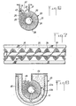
- FIG. 6 represents a cross section looking downstream, that is to say in the direction of flow of the products, of a machine according to the invention comprising a single helical brush composed of a drive shaft 24 on which is implanted a helical brush formed of bristles 25.
- Figure 6 corresponds to a propeller having a left pitch which is rotated clockwise.
- the products to be coated accumulate by forming a heap 26 along the side wall of the trough 23 which is swept by the bristles of the brush in the upward direction.
- the gauge 23 has a bottom 28 in the form of a half-cylinder which follows the outline of the helical brush.
- the side wall 29 of the trough situated on the side which is swept upwards is connected tangentially to the cylindrical bottom 28.
- the wall 30 of the trough which is swept by the helical brush in the downward direction has the shape of a portion of cylinder which extends the cylindrical bottom 28, so that the trough envelops the helical brush over more than half of its periphery.
- the cylindrical wall 30 extends up to the vertical of the axis of the shaft 24, so that the trough envelops three quarters of the periphery of the brush.
- the cylindrical wall 30 is extended upwards by a flat wall 31 which can be vertical or slightly oblique and which defines with the wall 29 a chute 32 surmounting the brush.
- This arrangement has, in the case of a machine with a single brush, the same advantages as the embodiment according to FIG. 5.
- the helical brush is held in the bottom of the trough by the cylindrical wall 30 without that it is necessary to mount the shaft 24 in bearings.
- the excess products go up into the chute 32 where they escape the action of the brush and the wall 30 prevents them from being rotated around the shaft 24 and they do not join the cluster which precedes them.
- FIG. 6 shows a cleaning device which can be applied to all the machines according to the invention.
- This device comprises one or more ramps 33, 34 which distribute a cleaning liquid, for example hot water, all along the trough.
- These ramps can be perforated tubes or tubes fitted with sprayers which project jets of sprayed liquid into the trough.
- the machines according to the invention in particular those which are used to manufacture products coated with sugar, tend to become dirty and it is necessary to clean them after each work station.
- FIG. 7 represents a partial top view of an alternative embodiment of a machine according to the invention.
- FIG. 7 shows an example of a machine comprising a trough 35 composed of a bottom in the form of a half-cylinder extended by two vertical side walls.
- the trough could also have the shape shown in FIG. 6.
- the coating machines according to the invention rotate at very slow speeds of between 20 rpm and 100 rpm. As a result, their throughput is very reduced. To increase the flow, the idea that naturally comes to mind is to increase the pitch, so that the axial speed of movement of the products increases.
- FIG. 7 represents an alternative embodiment which makes it possible to increase the flow rate of the machine, without increasing the speed of rotation and without increasing the volume of the individual piles 36 of products to be coated.
- the machine comprises a rigid drive shaft 37 and two helical brushes 38 and 39, of the same pitch and of the same direction which are interlaced, that is to say that they are axially offset by a half -not.
- the machine delivers two clusters 36 but these are separated by a layer of bristles as they progress along the trough.
- Clusters 36 which are smaller are better stirred and the coating is more uniform.
- each cluster 36 For the same flow rate of the machine, the quantity of products in each cluster 36 is divided by two and each cluster therefore exerts a lower pressure on the brush. It is thus possible to obtain a higher flow rate while maintaining a low speed of rotation and a uniform coating of the products.
- FIG. 7 can also be applied to a machine according to FIG. 3 which would then comprise two shafts each carrying two crossed helical brushes.
- FIG. 8 represents a cross section of an alternative embodiment of a part of a machine according to the invention intended for manufacturing popped cereals of the popcorn type.
- the manufacture of these cereals comprises a step of coating in oil, possibly steps of coating in products such as honey or sugar and a step of bursting in contact with a wall heated to a temperature between 120 ° and 150 °.
- Figure 8 shows a section of the part of the machine in which the burst takes place, this part following a part where the coating took place.
- FIG. 8 represents an example of a machine comprising a trough 40 similar to that of FIG. 6 and a single helical propeller.
- the embodiment according to FIG. 8 can also comprise a trough having two flat side walls or a machine according to FIGS. 3 to 5 comprising two parallel endless screws or a machine according to FIG. 7 comprising two crossed helical brushes.
- the helical brush of the machine according to FIG. 8 is composed of bristles 41 which are strands of stainless steel which are implanted on a metallic drive shaft 42 following a helix having a left pitch.
- the figure is a view looking in the direction of flow of the products, the shaft 42 is driven in a clockwise direction.
- the gauge 40 has a double wall 43a, 43b which delimits an intermediate space 44 in which a heat transfer fluid is circulated, for example dry steam or an oil at a temperature of the order of 150%, so that the cereals 45 burst on contact with the hot wall.
- a heat transfer fluid for example dry steam or an oil at a temperature of the order of 150%.
- the mixing of the products due to the action of the brush causes all the cereals to come into contact with the hot wall and burst.
- the outer wall 43a carries a heat-insulating coating 46.
- a metal trough can be used which is heated locally by burner flames or by electrical resistances arranged inside a heat-insulated box. .
- FIG. 6 shows an exemplary embodiment in which the vertical wall 29, which is swept by the bristles of the brush in the upward direction and against which the products accumulate 26, comprises a rib 47 projecting from the inside of chute 32.
- This rib is disposed substantially at the level of the upper generatrix of said helical brush 25.
- the products located below the rib 47 are constantly renewed by new products pushed by the brush.
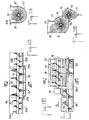
- FIGS. 9 and 10 respectively represent a partial top view and a cross section along X-X of an alternative embodiment of a coating machine according to FIG. 3.
- the machine comprises two helical brushes 49d, 49g whose drive shafts 50d, 50g are arranged parallel in the bottom of a trough 51.
- the arrow F indicates the direction of flow of the products.
- the two helical brushes have reverse steps.
- the brush 49d is rotated clockwise and has a step to the left.
- the 49g brush is rotated counterclockwise and has a step to the right.
- FIG. 3 represents a machine in which the two brushes are arranged symmetrically with respect to the longitudinal median plane MM '.
- Figure 9 shows a variant in which the two helical brushes are offset longitudinally relative to each other.
- the solid cores to be coated 52 progress in the central zone located between the two helical brushes which move from bottom to top and the cores undergo, in this zone, continuous rotational movements both in the longitudinal direction and in the transverse direction which lead to a very homogeneous coating on all the faces of the core.
- the intensive mixing of the particles is improved by slightly modifying the shape of the bottom of the trough which comprises, between the two brushes, a rib 53 of rounded shape which facilitates the routing of the particles.
- Figures 3 and 9 show helical brushes which are tangent to the median plane MM '. It is specified that this provision is not limiting. The brushes can be slightly moved away from the median plane or, on the contrary, they can slightly overlap the median plane.
- the two brushes of a machine according to FIGS. 9 and 10, which have opposite pitches and directions of rotation can be driven in rotation either at the same speed, or at different speeds to increase the mixing of the cores.
- FIGS. 9 and 10 show a machine equipped with a device 81, in the form of a double slope roof which is symmetrical with respect to the median plane MM 'and which is located above the two brushes.
- the device 81 avoids projections of products out of the trough and the formation of deposits against the vertical walls of the trough.
- the device 81 can be produced in several removable sections, which makes it possible to remove certain sections where it is desired to introduce products into the trough.
- a machine according to the invention is frequently used for coating soft gelatinous or pasty cores which are fragile and easily deformable products and the introduction of these products into the machine requires precautions.
- Soft cores cannot be poured vertically into the trough because a large number would skewer on the wires of the spindle and be broken, which would lead to the production of an unacceptable finished product.
- Figures 11 and 12 show a device for introducing fragile products into the upstream end of a machine according to the invention which comprises a trough 53 and a single helical brush 54 which has a pitch to the right and which is driven in the counterclockwise.
- the upstream end of the trough is located above an endless belt conveyor 55 which moves perpendicular to the axis of the helical brush.
- the gauge has a lateral opening whose width is substantially equal to that of the conveyor and this opening is located on the side of the trough which is swept by the bristles of the brush in the descending direction and it faces the conveyor 55.
- the brush bristles rub against the upper strand of the endless belt on which the products 58 are located which are poured for example by a chute 57.
- the lower edge 59 of the opening 56 is placed against the upper face of the conveyor belt .
- the products 58 are pushed inside the trough by the bristles of the brush and they gather in clusters in the upper part of the edge of the trough which is swept by the bristles in the upward direction.
- Figures 13 and 14 show a longitudinal section and a cross section along XIV-XIV of a part of a machine according to the invention, used for continuous cooking in a hot oil bath of food products, for example peanuts or almonds or extruded pasta.
- the machine comprises a stainless steel trough 60 open on the top, in which a shaft 61 made of stainless steel is disposed which is rotated at a low speed of less than 50 revolutions / minute.
- the shaft 61 carries helical brushes composed of flexible stainless steel strands which are installed radially and helically on the shaft 61.
- the gauge 60 has a central section 62 interposed between two sections 63a and 63b of smaller cross section to which it is connected by a frustoconical part.
- the shaft 61 carries a helical brush 64 which is disposed along the central section 62 and which comprises steel strands whose length is substantially equal to the distance separating the periphery of the shaft 61 from the bottom of the trough 62
- the shaft 61 carries two helical brushes 65a and 65b of smaller diameter located on either side of the brush 64.
- the central section 62 contains in its bottom a bath of hot oil 66 which circulates, preferably, against the current of the direction of circulation of the products represented by the arrow F1.
- the hot bath arrives at the bottom of the trough through an inlet 67a and it exits through the outlet 67b.
- the circuit in which the oil circulates comprises a circulation pump, means for heating the oil and a filter for stopping the products in suspension.
- the height of the oil bath 66 is kept less than the depth of the bottom of the trough 62 relative to the bottoms of the troughs 63a and 63b, so that the oil remains in the central trough 62 where the cooking of the products.
- a machine according to Figures 13 and 14 can be used to cook either heavier products than oil, such as peanuts, which fall to the bottom of trough 62, or lighter products which float on the surface of the bath.
- the flexible steel strands of the helical brushes exert a triple action of product advancement, stirring with inversion and permanent sweeping of the trough walls against which the strands rub.
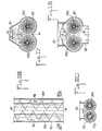
- Figures 15 and 16 respectively represent a top view and a cross section along XVI-XVI of another embodiment of a machine according to the invention which is used both for coating and for cooking food products in particular for manufacturing popcorn popped cereals.
- split cereals involves a first operation during which grains of corn, rice or wheat are coated with oil and other products such as sugar, salt, honey, chocolate and then they are heated to pop them.
- Figures 15 and 16 show a machine capable of performing these successive operations.
- This machine comprises a first trough 68 which contains a first helical brush, constituted by a stainless steel shaft 69, carrying stainless steel strands 70 implanted along a helix having a pitch to the left.
- the shaft 69 is rotated clockwise by a motor 71, at low speed, less than 100 rpm.
- the cereals are poured into the trough 68 at the end situated on the left in the figure and they are moved in the direction of the arrow F2.
- the cereals form clusters against the side wall of the trough which is swept by the bristles of the brush in the upward direction and they rotate on themselves, which makes it possible to coat them uniformly with oil, honey or powdery products such as salt, sugar, cocoa.
- the cereal coating takes place in the section of the trough 68 located to the left of the figure and in this section, the trough has an opening, at its upper part, in which the heaps of cereals are formed and the mixing of these as previously explained.
- the gauge 68 is extended to the right by a section 68a, in which the bursting of the cereals takes place.
- This section of trough has a thick wall which is good conductor of heat, for example a copper wall and it is heated for example by the flame 72 of a burner or by electric resistances or by any other heating means equivalent to a sufficient temperature to pop oil-soaked cereals.
- the machine comprises a second trough 73 which is located above the section 68a and which is offset laterally relative to the latter.
- the gauge 73 contains a shaft 74 which is rotated clockwise, at a speed of less than 100 rpm by a motor 75 and the shaft 74 carries strands of stainless steel forming a helical brush 76 having a step to the left.
- the gauge 73 has in its upper part an opening 77 having a vertical side wall which extends the circular bottom of the trough which is swept up by the bristles of the brush and the exploded grains form clusters 78, located between the layers of bristles of the brush and against the vertical wall of the opening 77 as explained above.
- the circular bottom of the trough 73 and the brush 76 have a diameter greater than the diameter of the circular bottom of the trough 68, 68a and that of the brush 70.
- the section 68a of the lower trough is closed on top by a circular wall which has a lateral opening 79 which is placed opposite a lateral opening in the bottom of the trough 73 , the two troughs being fixed to each other along the two longitudinal edges of the common opening 79 by screws, by welding or by any other equivalent means.
- the opening 79 of the lower trough extends substantially over the entire upper quadrant of the trough which is located on the side which is swept up by the brush 70.
- the operation is as follows.
- the cereals poured into the trough 68 are uniformly coated with oil and possibly with other products as they move in this trough in the direction of the arrow F2.
- the coated cereals arrive in the heated section 68a where they burst. Their volume increases considerably and their density decreases.
- the exploded cereals are entrained by the brush 70 towards the opening 79 and under the effect of the increase in volume and the pressure due to the bursts, they penetrate into the bottom of the trough 73 where they are swept by the bristles of the brush 76 which drives them upwards where they form the heaps 78.
- the exploded cereals are evacuated as and when they are produced out of the section 68a where they risk being damaged.
- the brush 76 disposed in the trough 73 is capable of absorbing the increase in volume due to the expansion of the cereals.
- the exploded cereals accumulate in the orifice 79 located between the two troughs before being taken up by the brush 76 and they form a screen which reduces the heat losses out of the trough 68a and which avoids too great an elevation of temperature in trough 73.
- FIG. 17 shows a cross section of an alternative embodiment of a machine according to the invention comprising two helical brushes 82g and 82d, rotating in opposite directions to each other, arranged in a trough 83.
- the side walls of the trough have, in the lower part, a cylindrical shape which envelops the helical brushes.
- the machine comprises a radiant heat source 84, constituted for example by an infrared emitter which is situated above the intermediate part between the two brushes in which the products to be coated accumulate.
- a radiant heat source 84 constituted for example by an infrared emitter which is situated above the intermediate part between the two brushes in which the products to be coated accumulate.
- FIG. 18 represents a cross section of an alternative embodiment of a machine according to the invention comprising a section for cooling the products by a stream of cold air or drying by a stream of hot air.
- This machine comprises, like the previous one, two helical brushes 85g, 85d rotating in opposite directions, arranged in a fixed trough 86 having cylindrical walls which surround the external part of the helical brushes.
- the central part 87 of the bottom of the trough is perforated and it communicates with a sheath 88 which blows cold or hot air depending on the applications.
- the gauge comprises air extraction means, for example a suction sheath 89 which is placed above the brushes and which is supported by the vertical walls of the trough 86.
- the air which arrives through the sheath 88 passes through the perforated bottom 87 then through the products 90 which are concentrated in the central part located between the two brushes and it is taken up by the sheath 89.
- the intensive mixing of the products 90 allows very rapid cooling or drying of these on all their faces.
- Figures 19 and 20 show a partial top view and a cross section of an alternative embodiment of a machine according to the invention.
- Figures 3 and 9 show machines which have two helical brushes rotated in opposite directions to each other and having steps in opposite directions, so that the two brushes drive the products longitudinally in the same direction.
- the translation speeds can be unequal, either that the rotational speeds are unequal, or that the steps have different lengths.
- Figures 19 and 20 show an alternative embodiment of a machine comprising two helical brushes 91d, 91g, placed in the same trough 92, in which the two helical brushes are always rotated in opposite directions from one another , so that they move upwards in the central part, but the steps of the two brushes are in the same direction, so that the brushes drive the products longitudinally with translation speeds of opposite direction and uneven.
- the brush 91g which rotates anti-clockwise, has a step to the right and it drives the products with a translation speed represented by the arrow VA
- the brush 91d which rotates in clockwise, also has a step to the right and it drives the products in translation with a speed VB which is in the opposite direction to the speed VA and which is significantly lower in absolute value than VA.
- the speed VA is greater than twice VB.
- the steps of the two brushes are equal and the speed difference is obtained by rotating the brush 91 d slower than the brush 91g.
- the brush 91d can have the same speed of rotation as the brush 91g, but a shorter pitch.
- the product of the pitch by the speed of rotation of one brush is significantly greater than the product of the pitch by the speed of rotation of the other brush.
- the cores 93 which accumulate between the two brushes are driven alternately by one or the other of the two brushes, sometimes in one direction, sometimes in the other, so that they follow a path curvy with loops and they stay longer in the machine.
- the speed VA is much higher than VB, the average speed of the nuclei is directed along VA.
- a machine according to FIGS. 19 and 20 makes it possible to obtain a very uniform coating with brushes of reduced length. It also makes it possible to coat low core flow rates.
Priority Applications (1)
| Application Number | Priority Date | Filing Date | Title |
|---|---|---|---|
| AT85430045T ATE39044T1 (de) | 1985-01-09 | 1985-12-23 | Maschine zum kontinuierlichen und gleichmaessigen ueberziehen von konditorwaren. |
Applications Claiming Priority (4)
| Application Number | Priority Date | Filing Date | Title |
|---|---|---|---|
| FR8500412 | 1985-01-09 | ||
| FR8500412A FR2575639B1 (fr) | 1985-01-09 | 1985-01-09 | Procede et machine pour enrober uniformement en continu des produits tels que des bonbons ou des biscuits d'aperitif |
| FR8508702 | 1985-06-06 | ||
| FR8508702A FR2582913B2 (fr) | 1985-06-06 | 1985-06-06 | Machine pour enrober uniformement en continu des produits tels que des bonbons ou des biscuits d'aperitif. |
Publications (3)
| Publication Number | Publication Date |
|---|---|
| EP0192012A2 EP0192012A2 (fr) | 1986-08-27 |
| EP0192012A3 EP0192012A3 (en) | 1987-01-07 |
| EP0192012B1 true EP0192012B1 (fr) | 1988-12-07 |
Family
ID=26224330
Family Applications (1)
| Application Number | Title | Priority Date | Filing Date |
|---|---|---|---|
| EP85430045A Expired EP0192012B1 (fr) | 1985-01-09 | 1985-12-23 | Machines pour enrober uniformément en continu des produits de confiserie |
Country Status (5)
| Country | Link |
|---|---|
| US (1) | US4658708A (ja) |
| EP (1) | EP0192012B1 (ja) |
| JP (1) | JPH0685691B2 (ja) |
| DE (1) | DE3566607D1 (ja) |
| ES (1) | ES8701531A1 (ja) |
Families Citing this family (42)
| Publication number | Priority date | Publication date | Assignee | Title |
|---|---|---|---|---|
| FR2596956B1 (fr) * | 1986-04-14 | 1989-09-08 | Transitube Project | Machine pour fabriquer des produits enrobes |
| CH670034A5 (ja) * | 1986-12-09 | 1989-05-12 | Nestle Sa | |
| DE3803756C1 (ja) * | 1988-02-08 | 1989-04-27 | Kraft Gmbh, 8998 Lindenberg, De | |
| US4813531A (en) * | 1988-03-10 | 1989-03-21 | Xerox Corporation | Developer transport apparatus |
| DE3828740A1 (de) * | 1988-08-24 | 1990-03-08 | Apetito Karl Duesterberg Kg | Verfahren zur herstellung von beliebig portionierbaren tiefkuehl-fertiggerichten |
| US5435430A (en) * | 1989-01-13 | 1995-07-25 | Nabisco, Inc. | Bucket conveying method and apparatus |
| FR2652236B1 (fr) * | 1989-09-27 | 1991-12-06 | Gontero Roger | Machine et procede pour le traitement en continu de surface d'articles de grosseur reduite. |
| US5118515A (en) * | 1990-11-14 | 1992-06-02 | Gruma, S.A. De C.V. | Preventing sticking of stacked food products |
| US5304386A (en) * | 1991-05-30 | 1994-04-19 | Dugas Jeffrey J | Edible container and process for the fabrication thereof |
| FR2686964B1 (fr) * | 1992-01-30 | 1998-10-30 | Anhydride Carbonique Ind | Appareil de refroidissement cryogenique en continu de produits particulaires a caractere pateux ou solide. |
| US5516541A (en) * | 1994-04-04 | 1996-05-14 | Kellogg Company | No dry coating process for sugar coated food products |
| US5645878A (en) * | 1994-04-04 | 1997-07-08 | Kellogg Company | No dry coating process for coated food products |
| US5514399A (en) * | 1994-06-27 | 1996-05-07 | Nabisco, Inc. | Method of applying particulates to baked goods and snacks |
| US5698252A (en) * | 1995-05-31 | 1997-12-16 | Nabisco Technology Company | Topical application of particulates for production of reduced fat, low fat, and no-fat baked goods and snacks |
| FR2774265B1 (fr) * | 1998-02-02 | 2000-03-31 | Alain Keddar | Installation d'enrobage sous vide de produits se presentant sous la forme de granules |
| WO1999044443A1 (en) * | 1998-03-03 | 1999-09-10 | Mjm Technologies, L.L.P. | Vegetative sterilization method |
| WO2001072134A1 (en) * | 2000-03-24 | 2001-10-04 | Societe Des Produits Nestle S.A. | Coated biscuit |
| EP1508278A4 (en) * | 2002-05-29 | 2010-04-21 | Ishida Seisakusho | SEASONING DEVICE AND PRODUCT PRODUCTION SYSTEM USING SAID DEVICE |
| AU2003256799A1 (en) * | 2002-07-25 | 2004-02-16 | University Of Florida | Flexible screw feeder/mixer for precision dosing and feeding of particulate systems |
| US7347933B2 (en) * | 2003-11-17 | 2008-03-25 | Intake Screens, Inc. | Self-cleaning intake screen |
| US7807209B1 (en) * | 2005-08-31 | 2010-10-05 | Milne Fruit Products, Inc. | Watermelon juice products and food products produced with the juice products |
| US7641460B2 (en) * | 2006-05-30 | 2010-01-05 | C. Cretors & Company | Cotton candy handling device |
| US8323711B2 (en) * | 2007-10-09 | 2012-12-04 | Mars, Incorporated | Spiral gas-solids contact apparatus and method |
| DE102009050176B4 (de) * | 2009-10-21 | 2018-02-01 | Tracto-Technik Gmbh & Co. Kg | Bohrvorrichtung, Verwendung einer Bohrvorrichtung und Mischanlage für eine Bohrvorrichtung |
| EP2351490B1 (en) * | 2010-01-27 | 2018-10-17 | Kraft Foods R & D, Inc. | A device and a process for continuously feeding chocolate ingredients as well as a system and a process for producing a chocolate mass |
| US9198532B2 (en) | 2010-05-07 | 2015-12-01 | National Presto Industries, Inc. | Energy efficient apparatus and method for popping popcorn |
| JP2013156535A (ja) * | 2012-01-31 | 2013-08-15 | Konica Minolta Inc | 画像形成装置 |
| US8302780B1 (en) * | 2012-02-22 | 2012-11-06 | M2 Renewables, Inc. | Industrial separator and dewatering plant |
| CN105899085A (zh) * | 2014-01-24 | 2016-08-24 | 康菲泰克有限公司 | 用于生产诸如糖果等的糖食产品的设施 |
| CN107348550A (zh) | 2016-04-06 | 2017-11-17 | 茜·克里特斯公司 | 具有燃气辐射式燃烧器的爆米花机器及相关系统和方法 |
| US10631562B2 (en) | 2016-11-23 | 2020-04-28 | C. Cretors & Company | Continuous popcorn machines having variable heating profiles and associated systems and methods |
| US11044929B2 (en) * | 2016-12-16 | 2021-06-29 | C. Cretors & Company | Popcorn machines having process chambers of increasing volume, and associated systems and methods |
| US10604462B2 (en) * | 2017-08-28 | 2020-03-31 | Exxonmobil Chemical Patents Inc. | Process for making gamma-branched alcohol |
| WO2019045809A1 (en) * | 2017-08-28 | 2019-03-07 | Exxonmobil Chemical Patents Inc. | PROCESS FOR THE PRODUCTION OF A GAMMA BRANCH ALCOHOL |
| WO2019045810A1 (en) | 2017-08-28 | 2019-03-07 | Exxonmobil Chemical Patents Inc. | ESTER COMPOUNDS, LUBRICATING OIL COMPOSITIONS CONTAINING THE SAME AND METHODS OF MAKING THE SAME |
| US10654766B2 (en) | 2017-08-28 | 2020-05-19 | Exxonmobil Chemical Patents Inc. | Process for making vinylidene olefin |
| CN111328326B (zh) | 2017-09-29 | 2023-02-21 | 埃克森美孚化学专利公司 | 新酸及其制备方法 |
| CN209931412U (zh) | 2017-12-05 | 2020-01-14 | 茜·克里特斯公司 | 爆米花机 |
| US20190297926A1 (en) * | 2018-04-02 | 2019-10-03 | C. Cretors & Company | Continuous popcorn machines and associated systems and methods |
| US11930967B2 (en) | 2019-03-08 | 2024-03-19 | C. Cretors & Company | Food heaters, such as for use in heating hot dogs |
| US11172696B2 (en) | 2019-04-23 | 2021-11-16 | C. Cretors & Company | Popcorn machines having removable kettle assemblies |
| CN110535271B (zh) * | 2019-10-11 | 2021-04-06 | 台州泰立电器有限公司 | 一种转子铁芯 |
Family Cites Families (15)
| Publication number | Priority date | Publication date | Assignee | Title |
|---|---|---|---|---|
| US1374938A (en) * | 1920-04-30 | 1921-04-19 | William Prentiss Jr | Coating-machine |
| FR558454A (fr) * | 1921-11-16 | 1923-08-28 | Brogdex Co | Perfectionnements aux procédés, appareils et compositions pour le traitement des fruits frais |
| FR562054A (fr) * | 1922-02-14 | 1923-11-03 | Brogdex Co | Appareil pour munir les objets d'une couche de matière |
| US1529461A (en) * | 1923-08-13 | 1925-03-10 | Ernest M Brogden | Art of preparing fresh fruit for market |
| US1794346A (en) * | 1925-03-02 | 1931-02-24 | Brogdex Co | Preparation of fresh fruit for market |
| US1893672A (en) * | 1929-12-02 | 1933-01-10 | Lee G James | Machine for producing candy confection |
| US2033044A (en) * | 1930-07-11 | 1936-03-03 | Fmc Corp | Apparatus for treating fruit |
| US1985842A (en) * | 1932-10-13 | 1934-12-25 | Brogdex Co | Treatment of fresh fruit in preparation for market |
| GB856763A (en) * | 1958-07-07 | 1960-12-21 | City Bakeries Ltd | An improved apparatus for coating articles of confectionery with material in granulated or powdered form |
| NL246864A (ja) * | 1959-11-18 | |||
| BE645955A (ja) * | 1963-04-03 | 1964-07-16 | ||
| US3561981A (en) * | 1967-05-15 | 1971-02-09 | Nat Biscuit Co | Method for coating cereal with ice cream products |
| GB1484518A (en) * | 1976-07-14 | 1977-09-01 | Toms Foods Ltd | Snack products |
| US4189289A (en) * | 1977-03-28 | 1980-02-19 | Vroman Foods, Inc. | Method and apparatus for producing and processing frozen confections |
| US4192418A (en) * | 1978-05-04 | 1980-03-11 | Montgomery Max L | Auger conveyer |
-
1985
- 1985-12-23 EP EP85430045A patent/EP0192012B1/fr not_active Expired
- 1985-12-23 DE DE8585430045T patent/DE3566607D1/de not_active Expired
- 1985-12-31 US US06/814,750 patent/US4658708A/en not_active Expired - Fee Related
-
1986
- 1986-01-08 ES ES551289A patent/ES8701531A1/es not_active Expired
- 1986-01-09 JP JP61001473A patent/JPH0685691B2/ja not_active Expired - Lifetime
Also Published As
| Publication number | Publication date |
|---|---|
| ES551289A0 (es) | 1987-01-01 |
| JPH0685691B2 (ja) | 1994-11-02 |
| DE3566607D1 (en) | 1989-01-12 |
| US4658708A (en) | 1987-04-21 |
| JPS61224938A (ja) | 1986-10-06 |
| EP0192012A3 (en) | 1987-01-07 |
| ES8701531A1 (es) | 1987-01-01 |
| EP0192012A2 (fr) | 1986-08-27 |
Similar Documents
| Publication | Publication Date | Title |
|---|---|---|
| EP0192012B1 (fr) | Machines pour enrober uniformément en continu des produits de confiserie | |
| EP0485654B1 (fr) | Procédé et appareil de fabrication d'un article de dessert aéré | |
| CA2066737C (fr) | Machine et procede pour le traitement en continu de surface d'articles de grosseur reduite | |
| EP0628254A1 (fr) | Procédé et appareil de fabrication d'articles de confiserie glacée | |
| EP0373246B1 (fr) | Dispositif de formage de confiserie glacée | |
| KR20050040608A (ko) | 곡물을 이용한 건과자 가공장치 및 제조방법 | |
| EP1118269A1 (fr) | "Méthode de fabrication de barres de confiserie" | |
| FR2483181A1 (fr) | Vis pour l'extrusion d'une pate alimentaire | |
| WO2004010801A2 (fr) | Produit alimentaire enrobe, composition, procede et appareil pour sa fabrication | |
| FR2646589A1 (fr) | Procede et dispositif de cuisson automatique de produits alimentaires | |
| EP0811324B1 (fr) | Procédé et dispositif de fabrication de crème glacée contenant des morceaux | |
| FR2680635A1 (fr) | Confiserie composite a croquer a base de produit glace et son procede d'obtention. | |
| FR2512328A1 (fr) | Procede et dispositif pour la fabrication d'une patisserie creuse, fourree au moins partiellement sur son cote interne | |
| EP1955603A1 (fr) | Procède de depelliculage de graines de fruits a coques, dispositif associe et produits alimentaires obtenus | |
| FR2582913A2 (fr) | Machine pour enrober uniformement en continu des produits tels que des bonbons ou des biscuits d'aperitif. | |
| FR2502466A1 (fr) | Turbine pour l'enrobage de dragees de produits alimentaires ou pharmaceutiques | |
| FR2575639A1 (fr) | Procede et machine pour enrober uniformement en continu des produits tels que des bonbons ou des biscuits d'aperitif | |
| EP0043324A1 (fr) | Machine pour peler et torréfier et nettoyer les graines de sésame | |
| FR2725113A1 (fr) | Produit alimentaire compose de parties de fruits durs agglomerees en lots calibres, procede et dispositif pour l'obtention de ce produit | |
| FR2698763A1 (fr) | Procédé de traitement thermique de produits alimentaires, notamment de cuisson de légumes, et dispositif pour sa mise en Óoeuvre. | |
| FR2693634A1 (fr) | Produit alimentaire notamment du type biscuit ou pâtisserie et son procédé de fabrication. | |
| FR2584268A1 (fr) | Produit de boulangerie, en particulier pour la fabrication de patisseries fourrees, et procede pour sa preparation | |
| FR2722656A1 (fr) | Procede et installation pour le tranchage, le dosage et la repartion, sur une surface donnee d'un suuit alimentaire, en particulier de legumes ou de fpport, du type plateau ou fond de tarte, d'un prodruits | |
| EP0914214A1 (fr) | Installation pour l'enrobage de produits alimentaires ou pharmaceutiques | |
| FR2774265A1 (fr) | Installation d'enrobage sous vide de produits se presentant sous la forme de granules |
Legal Events
| Date | Code | Title | Description |
|---|---|---|---|
| PUAI | Public reference made under article 153(3) epc to a published international application that has entered the european phase |
Free format text: ORIGINAL CODE: 0009012 |
|
| AK | Designated contracting states |
Kind code of ref document: A2 Designated state(s): AT BE CH DE FR GB IT LI LU NL SE |
|
| PUAL | Search report despatched |
Free format text: ORIGINAL CODE: 0009013 |
|
| AK | Designated contracting states |
Kind code of ref document: A3 Designated state(s): AT BE CH DE FR GB IT LI LU NL SE |
|
| 17P | Request for examination filed |
Effective date: 19861215 |
|
| 17Q | First examination report despatched |
Effective date: 19880517 |
|
| GRAA | (expected) grant |
Free format text: ORIGINAL CODE: 0009210 |
|
| AK | Designated contracting states |
Kind code of ref document: B1 Designated state(s): AT BE CH DE FR GB IT LI LU NL SE |
|
| PG25 | Lapsed in a contracting state [announced via postgrant information from national office to epo] |
Ref country code: SE Effective date: 19881207 Ref country code: AT Effective date: 19881207 |
|
| REF | Corresponds to: |
Ref document number: 39044 Country of ref document: AT Date of ref document: 19881215 Kind code of ref document: T |
|
| PG25 | Lapsed in a contracting state [announced via postgrant information from national office to epo] |
Ref country code: LU Free format text: LAPSE BECAUSE OF NON-PAYMENT OF DUE FEES Effective date: 19881231 |
|
| REF | Corresponds to: |
Ref document number: 3566607 Country of ref document: DE Date of ref document: 19890112 |
|
| GBT | Gb: translation of ep patent filed (gb section 77(6)(a)/1977) | ||
| ITF | It: translation for a ep patent filed |
Owner name: JACOBACCI & PERANI S.P.A. |
|
| PLBE | No opposition filed within time limit |
Free format text: ORIGINAL CODE: 0009261 |
|
| STAA | Information on the status of an ep patent application or granted ep patent |
Free format text: STATUS: NO OPPOSITION FILED WITHIN TIME LIMIT |
|
| PGFP | Annual fee paid to national office [announced via postgrant information from national office to epo] |
Ref country code: LU Payment date: 19891128 Year of fee payment: 5 |
|
| 26N | No opposition filed | ||
| ITTA | It: last paid annual fee | ||
| PGFP | Annual fee paid to national office [announced via postgrant information from national office to epo] |
Ref country code: NL Payment date: 19971130 Year of fee payment: 13 |
|
| PGFP | Annual fee paid to national office [announced via postgrant information from national office to epo] |
Ref country code: CH Payment date: 19980106 Year of fee payment: 13 |
|
| PGFP | Annual fee paid to national office [announced via postgrant information from national office to epo] |
Ref country code: BE Payment date: 19980115 Year of fee payment: 13 |
|
| PG25 | Lapsed in a contracting state [announced via postgrant information from national office to epo] |
Ref country code: LI Free format text: LAPSE BECAUSE OF NON-PAYMENT OF DUE FEES Effective date: 19981231 Ref country code: CH Free format text: LAPSE BECAUSE OF NON-PAYMENT OF DUE FEES Effective date: 19981231 Ref country code: BE Free format text: LAPSE BECAUSE OF NON-PAYMENT OF DUE FEES Effective date: 19981231 |
|
| BERE | Be: lapsed |
Owner name: TRANSITUBE PROJET Effective date: 19981231 |
|
| PG25 | Lapsed in a contracting state [announced via postgrant information from national office to epo] |
Ref country code: NL Free format text: LAPSE BECAUSE OF NON-PAYMENT OF DUE FEES Effective date: 19990701 |
|
| REG | Reference to a national code |
Ref country code: CH Ref legal event code: PL |
|
| NLV4 | Nl: lapsed or anulled due to non-payment of the annual fee |
Effective date: 19990701 |
|
| PGFP | Annual fee paid to national office [announced via postgrant information from national office to epo] |
Ref country code: DE Payment date: 20011212 Year of fee payment: 17 |
|
| PGFP | Annual fee paid to national office [announced via postgrant information from national office to epo] |
Ref country code: GB Payment date: 20011218 Year of fee payment: 17 |
|
| PGFP | Annual fee paid to national office [announced via postgrant information from national office to epo] |
Ref country code: FR Payment date: 20011228 Year of fee payment: 17 |
|
| REG | Reference to a national code |
Ref country code: GB Ref legal event code: IF02 |
|
| PG25 | Lapsed in a contracting state [announced via postgrant information from national office to epo] |
Ref country code: GB Free format text: LAPSE BECAUSE OF NON-PAYMENT OF DUE FEES Effective date: 20021223 |
|
| PG25 | Lapsed in a contracting state [announced via postgrant information from national office to epo] |
Ref country code: DE Free format text: LAPSE BECAUSE OF NON-PAYMENT OF DUE FEES Effective date: 20030701 |
|
| GBPC | Gb: european patent ceased through non-payment of renewal fee |
Effective date: 20021223 |
|
| PG25 | Lapsed in a contracting state [announced via postgrant information from national office to epo] |
Ref country code: FR Free format text: LAPSE BECAUSE OF NON-PAYMENT OF DUE FEES Effective date: 20030901 |
|
| REG | Reference to a national code |
Ref country code: FR Ref legal event code: ST |