EP0191362B1 - Fuel supplying pump - Google Patents
Fuel supplying pump Download PDFInfo
- Publication number
- EP0191362B1 EP0191362B1 EP86101149A EP86101149A EP0191362B1 EP 0191362 B1 EP0191362 B1 EP 0191362B1 EP 86101149 A EP86101149 A EP 86101149A EP 86101149 A EP86101149 A EP 86101149A EP 0191362 B1 EP0191362 B1 EP 0191362B1
- Authority
- EP
- European Patent Office
- Prior art keywords
- fuel
- pump
- suction port
- end cover
- fuel supplying
- Prior art date
- Legal status (The legal status is an assumption and is not a legal conclusion. Google has not performed a legal analysis and makes no representation as to the accuracy of the status listed.)
- Expired
Links
Images

Classifications
-
- F—MECHANICAL ENGINEERING; LIGHTING; HEATING; WEAPONS; BLASTING
- F02—COMBUSTION ENGINES; HOT-GAS OR COMBUSTION-PRODUCT ENGINE PLANTS
- F02M—SUPPLYING COMBUSTION ENGINES IN GENERAL WITH COMBUSTIBLE MIXTURES OR CONSTITUENTS THEREOF
- F02M37/00—Apparatus or systems for feeding liquid fuel from storage containers to carburettors or fuel-injection apparatus; Arrangements for purifying liquid fuel specially adapted for, or arranged on, internal-combustion engines
- F02M37/04—Feeding by means of driven pumps
- F02M37/08—Feeding by means of driven pumps electrically driven
- F02M37/10—Feeding by means of driven pumps electrically driven submerged in fuel, e.g. in reservoir
-
- F—MECHANICAL ENGINEERING; LIGHTING; HEATING; WEAPONS; BLASTING
- F02—COMBUSTION ENGINES; HOT-GAS OR COMBUSTION-PRODUCT ENGINE PLANTS
- F02M—SUPPLYING COMBUSTION ENGINES IN GENERAL WITH COMBUSTIBLE MIXTURES OR CONSTITUENTS THEREOF
- F02M37/00—Apparatus or systems for feeding liquid fuel from storage containers to carburettors or fuel-injection apparatus; Arrangements for purifying liquid fuel specially adapted for, or arranged on, internal-combustion engines
- F02M37/04—Feeding by means of driven pumps
- F02M37/08—Feeding by means of driven pumps electrically driven
-
- F—MECHANICAL ENGINEERING; LIGHTING; HEATING; WEAPONS; BLASTING
- F02—COMBUSTION ENGINES; HOT-GAS OR COMBUSTION-PRODUCT ENGINE PLANTS
- F02M—SUPPLYING COMBUSTION ENGINES IN GENERAL WITH COMBUSTIBLE MIXTURES OR CONSTITUENTS THEREOF
- F02M37/00—Apparatus or systems for feeding liquid fuel from storage containers to carburettors or fuel-injection apparatus; Arrangements for purifying liquid fuel specially adapted for, or arranged on, internal-combustion engines
- F02M37/22—Arrangements for purifying liquid fuel specially adapted for, or arranged on, internal-combustion engines, e.g. arrangements in the feeding system
Definitions
- the present invention generally relates to a fuel supplying pump and more particularly relates to an improvement in electric fuel supplying pumps which are operated in a condition of being placed at the bottom of a fuel tank of a motorcar, for instance, wherein the electric motor type fuel pump comprises a commutator motor as a driving member.
- the electric motor type fuel pump comprises a commutator motor as a driving member.
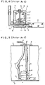
- Fig 4 is a cross-sectional view which shows an example of a conventional fuel supplying pump.
- the conventional fuel supplying pump consists of a motor part A, a pump part B and a fuel filtration device C.
- the motor part A comprises an armature 1, a permanent magnet 2, a collector part which includes a commutator 3 and brushes 4, a shaft 5, a thrust bearing 6 which supports an end part of the shaft 5, a motor casing 7 which contains the above-mentioned elements, and a bracket 8 which closes an lower opening of the motor casing 7 and supports the other end part of shaft 5 and further functions as a part of the below- mentioned pump casing 11.
- the pump part B furthermore comprises a suction port 9, an output port 10, a pump casing 11 and an impeller 12 which is fixed to the shaft 5 to constitute a peripheral type pump.
- the fuel filtration device C is connected with the above-mentioned suction port 9.
- the conventional fuel supplying pump is constructed as combination of the abovementioned motor part A, pump port B and fuel filtration device C.
- the peripheral type pump is coupled to a DC commutator motor so that the former is driven by the latter, and fuel is sucked into a pump chamber of the pump part B through the fuel filter and is pressurized and output through the output port.
- Fig. 5 Installation of the fuel supplying pump having the abovementioned construction in a fuel tank is made as shown in Fig. 5, wherein the fuel supplying pump P shown in Fig. 4 is held with a metal band a with a shock absorbing material, for instance rubber, therebetween, in a manner of being suspended by a supporting strip s from an inside face of a lid c disposed on a top face T, of the fuel tank T.
- a power source connection terminal d and a connecting tube e which is for connection of a fuel feeding hose connected to the fuel supplying pump P, are provided on the lid c.
- An output port P, of the fuel supplying pump P and the connecting tube e are each other connected by a rubber hose f.
- a relief valve y is provided as a pressure control device.
- Said power source connection terminal d is connected with a power source terminal of the fuel supplying pump P by conductor h.
- the pump P is installed at aposition close to the bottom face T 2 of the fuel tank, and is held there by means of the supporting strip s and the rubber hose f.
- US-A-2 319 934 shows a fuel supplying pump which is submerged in fuel contained in a fuel tank.
- a labyrinth is provided inside the pump casing consisting substantially of a volute member with a baffle, which is disposed between two coaxially arranged circumferential walls.
- This labyrinth must be manufactured with a high precision in order to achieve at a labyrinth width which prevents spreading of fire but has only a minimum of flow resistance to the sucked fuel.
- said high precision and the complicated structure of the pump according to US-A-2 319 934 lead to high costs and the possibilities of damages.
- the present invention is intended to solve the above-mentioned problems of the prior art, and the purpose of the present invention is to obtain a more saftely fuel supplying pump having a simple construction.
- the fuel supplying pump of the present invention is provided with an end cover having a suction port, between a pump casing having a suction port and fuel filtration element.
- the end cover is arranged in a manner that its suction port does not face the suction port of the pump casing.
- the fuel supplying pump embodying the present invention consists of a motor part A, a pump part B and a fuel filtration part C.
- the motor part A consists of a DC commutator motor which comprises an armature 1, a permanent magnet 2, a collector part which includes commutator 3 and brushes 4, a shaft 5, a thrust bearing 6 which supports an end part of the shaft 5, a motor casing 7 which contains the above-mentioned elements, and a bracket 8 which closes an lower opening of the motor case 7.
- a peripheral type pump is coupled to a DC commutator motor so that the former is driven by the latter, and fuel is sucked into a pump chamber 25 of the pump part B through the fuel filter and is pressurized and output through an output port.
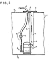
- a fuel supplying pump having the above-mentioned construction in a fuel tank is made as shown in Fig. 3, wherein the fuel supplying pump P is held with a metal band a with a shock absorbing material, for instance rubber, therebetween, in a manner of being suspended by a supporting strip s from an inside face of a lid c disposed on a top face T, of the fuel tank T.
- a power source connection terminal d and a connecting tube e which is for connection of a fuel feeding hose connected to the fuel supplying pump P, are provided on the lid c.
- An output port P, of the fuel supplying pump P and the connecting tube e are each other connected by a rubber-hose f and further, at the midway of said rubber hose f a relief valve y is provided as a pressure control device.
- Said power source connection terminal d is connected with a power source terminal of the fuel supplying pump P by conductor h.
- the pump P is installed ata postion close to the bottom face T2 of the fuel tank and is held there by means of the supporting strip s.
- a pump case 21 is provided with auction port 21 a and an output port 21 b (Fig. 1).
- An end cover 22 put on the lower part of the pump case 21 is arranged in a manner to make a fuel passage E between the pump case 21 and the end cover 22.
- a suction port 22a is provided on the end cover 22 at such a position apart from the suction port 21 a of a pump case 21 so as not to face the suction port 21 a, that is, positions of the two suction ports 21 a, 22a are separated by ⁇ degree from each other.
- a fuel filtration element 23 is provided to cover the lower part of said end cover 22, and is made of flexible or resilient synthetic fiber or soft and fine wires.
- the filtration element is mounted with its opening end part thereof on the outer circumferance of the lower part of the end cover and is fixed by a band 24, keeping appropriate gap between the lower end of the end cover 22 and the filtration element 23.
- the rubber hose f is connected with the output port 21 b.
- the pump casing 21 is covered with the pump cover 22 and furthermore the lower outside thereof is covered with the fuel filtration element 23, if the fuel vapor happens to catch fire at the collector, a spreading of fire to the fuel tank is prevented. Thus a more safety fuel pump is obtained.
- the present invention adopts a gap anti-explosion construction. Therefore even when the fuel vapor happens to catch fire, each connecting part is formed uneven in their inside shape when they are assembled, and further holes through which the fire flame passes are made as small as possible, a passage of fire flame is bent as far as possible to make the fire detour. Thereby the passage of fire is made long and narrow, and as a result, the fire flame is cooled and dispersed. Hence the energy of the fire decreases, and temperature of combustion is lowered, thus preventing the dangerous spreading of fire.
- the explosion preventing ability in dependent on size of the suction port 22a of end cover 22 and relation of hole position between the suction port 21 a of pump case 21 and the suction port 22a of end cover.
- Many explosive flush tests have been made for various combinations of the size of the holes of the sction ports 21 a, 22a and the relation of hole position, in a fuel supplying pump which supplies fuel with an internal-combustion engine of a motor car as in the embodiment of the present invention.
- the size of suction port 22a can not be made excessively small.
- suction port 22a when the size of suction port 22a is 4 mm in diameter, and the angular distance ⁇ between the suction part 22a and the output suction port 21 a is in a range of 120° - 240°, an anti-explosion ability in hydrogen gas of explosive grade No. 1 has been confirmed. Moreover, in a smaller discharge fuel supplying pump than the above example, it is possible to make the size of suction port 22a less than 4 mm in diameter, and further to select the angular distance 9 between the suction port 22a and output suction 21 a smaller than 120° - 240°, retaining the same anti-explosion ability.
- the fuel supplying pump of the present invention comprises the end cover 22 between the pump casing 21 and the fuel filtration element 23, said end cover having a hole, even when fuel vapor happens to catch fire under the condition that the fuel filtration element 23 is damaged and has a hole or has fallen off from the motor casing, such as by slipping out of the fixing band, dangerous spreading of a fire flame is prevented. Therefore, the fuel supplying pump according to the present invention is of high safety and has a simple configuration.
Landscapes
- Engineering & Computer Science (AREA)
- Chemical & Material Sciences (AREA)
- Combustion & Propulsion (AREA)
- Mechanical Engineering (AREA)
- General Engineering & Computer Science (AREA)
- Structures Of Non-Positive Displacement Pumps (AREA)
- Details Of Reciprocating Pumps (AREA)
Applications Claiming Priority (2)
| Application Number | Priority Date | Filing Date | Title |
|---|---|---|---|
| JP60017096A JPS61175262A (ja) | 1985-01-29 | 1985-01-29 | 燃料給送ポンプ |
| JP17096/85 | 1985-01-29 |
Publications (2)
| Publication Number | Publication Date |
|---|---|
| EP0191362A1 EP0191362A1 (en) | 1986-08-20 |
| EP0191362B1 true EP0191362B1 (en) | 1988-11-02 |
Family
ID=11934469
Family Applications (1)
| Application Number | Title | Priority Date | Filing Date |
|---|---|---|---|
| EP86101149A Expired EP0191362B1 (en) | 1985-01-29 | 1986-01-29 | Fuel supplying pump |
Country Status (5)
| Country | Link |
|---|---|
| US (1) | US4682936A (OSRAM) |
| EP (1) | EP0191362B1 (OSRAM) |
| JP (1) | JPS61175262A (OSRAM) |
| KR (1) | KR890000754B1 (OSRAM) |
| DE (1) | DE3661097D1 (OSRAM) |
Families Citing this family (25)
| Publication number | Priority date | Publication date | Assignee | Title |
|---|---|---|---|---|
| JPH0617032Y2 (ja) * | 1987-11-18 | 1994-05-02 | 三菱電機株式会社 | インタンク式燃料ポンプ |
| GB8903411D0 (en) * | 1988-03-09 | 1989-04-05 | Flowerday Michael J | Improvements relating to welded containers improvements to the manufacture of capacitive touch switches for use with operator control panels and probes |
| US5015156A (en) * | 1989-06-19 | 1991-05-14 | Scholz Daniel E | Aircraft fuel pump |
| US5215430A (en) * | 1992-02-26 | 1993-06-01 | J. C. Carter Company, Inc. | Ignition-source free fuel pump |
| US5329899A (en) * | 1993-10-12 | 1994-07-19 | General Motors Corporation | Fuel system pressure fuse |
| DE4343199A1 (de) * | 1993-12-17 | 1995-06-22 | Vdo Schindling | Saugstrahlpumpeneinheit |
| SE9501387D0 (sv) * | 1995-04-13 | 1995-04-13 | Electrolux Ab | Bränslematningssystem |
| US5806560A (en) * | 1996-10-22 | 1998-09-15 | J. C. Carter Company, Inc. | Aircraft fuel transfer pump with auxiliary fuel line scavenge pump |
| US6170472B1 (en) | 1997-06-04 | 2001-01-09 | Ford Global Technologies, Inc. | Fuel delivery module for an automotive fuel system |
| DE19823573B4 (de) * | 1997-11-12 | 2011-01-27 | Continental Automotive Gmbh | Kraftstoffördereinheit zum Einsatz in Kraftstofftanks |
| EP0916540A3 (de) * | 1997-11-12 | 2000-04-12 | Mannesmann VDO Aktiengesellschaft | Kraftstoffördereinheit mit einem Leitungsanschluss |
| US6095766A (en) * | 1998-07-29 | 2000-08-01 | Brown; Albert W. | Fuel transfer pump |
| US6494189B1 (en) | 1998-09-28 | 2002-12-17 | Parker-Hannifin Corporation | Flame arrestor system for fuel pump inlet |
| US6823831B2 (en) | 1998-09-28 | 2004-11-30 | Parker-Hannifin Corporation | Flame arrestor system for fuel pump discharge |
| DE19848571A1 (de) * | 1998-10-21 | 2000-05-04 | Bosch Gmbh Robert | Kraftstoff-Fördermodul |
| DE19926587A1 (de) * | 1999-06-11 | 2000-12-14 | Mannesmann Vdo Ag | Kraftstoffpumpe für ein Kraftfahrzeug |
| DE60138813D1 (de) * | 2000-08-14 | 2009-07-09 | Stanadyne Corp | Hochdruck-benzinpumpe die in einem kraftstofftank montiert ist |
| US6436287B1 (en) | 2000-12-20 | 2002-08-20 | Robert Bosch Corportion | Fuel pump module and method for installing the same |
| GB0123873D0 (en) * | 2001-10-04 | 2001-11-28 | Boc Group Plc | Mechanical pumps |
| JP2004124919A (ja) * | 2002-09-30 | 2004-04-22 | Aisan Ind Co Ltd | 内燃機関の燃料ポンプ |
| US7284969B2 (en) * | 2003-09-24 | 2007-10-23 | Jidosha Denki Kogyo Co., Ltd. | Washer pump and filter used for washer pump |
| GB0515155D0 (en) * | 2005-07-25 | 2005-08-31 | Boc Group Plc | Apparatus and method for inhibiting propagation of a flame front |
| JP2008047952A (ja) * | 2006-08-10 | 2008-02-28 | Kyocera Mita Corp | 画像形成装置 |
| US8220941B2 (en) | 2007-03-13 | 2012-07-17 | The Boeing Company | Compact high intensity solar simulator |
| CN103878120A (zh) * | 2014-03-08 | 2014-06-25 | 安徽万利达羽绒制品有限公司 | 一种羽绒收集车用过滤器 |
Family Cites Families (9)
| Publication number | Priority date | Publication date | Assignee | Title |
|---|---|---|---|---|
| US2319934A (en) * | 1939-08-23 | 1943-05-25 | Carter Carburetor Corp | Electric fuel pump |
| GB607852A (en) * | 1946-05-03 | 1948-09-06 | Self Priming Pump & Eng Co Ltd | Improvements in or relating to submerged fuel pump and motor units for aircraft |
| CA963728A (en) * | 1972-02-10 | 1975-03-04 | Russell Parrent | Submersible fuel pump |
| DE2637979A1 (de) * | 1976-08-24 | 1978-03-02 | Bosch Gmbh Robert | Kraftstoffoerderpumpe |
| JPS5488415U (OSRAM) * | 1977-12-05 | 1979-06-22 | ||
| US4209284A (en) * | 1978-09-01 | 1980-06-24 | General Motors Corporation | Electric motor-driven two-stage fuel pump |
| JPS5939189Y2 (ja) * | 1980-01-31 | 1984-10-31 | 日産自動車株式会社 | 流体移送用ポンプ装置 |
| JPS56169470U (OSRAM) * | 1980-05-19 | 1981-12-15 | ||
| JPS612296Y2 (OSRAM) * | 1981-05-19 | 1986-01-24 |
-
1985
- 1985-01-29 JP JP60017096A patent/JPS61175262A/ja active Granted
- 1985-07-23 KR KR1019850005253A patent/KR890000754B1/ko not_active Expired
-
1986
- 1986-01-27 US US06/823,098 patent/US4682936A/en not_active Expired - Lifetime
- 1986-01-29 EP EP86101149A patent/EP0191362B1/en not_active Expired
- 1986-01-29 DE DE8686101149T patent/DE3661097D1/de not_active Expired
Also Published As
| Publication number | Publication date |
|---|---|
| JPH0427383B2 (OSRAM) | 1992-05-11 |
| DE3661097D1 (en) | 1988-12-08 |
| JPS61175262A (ja) | 1986-08-06 |
| EP0191362A1 (en) | 1986-08-20 |
| US4682936A (en) | 1987-07-28 |
| KR890000754B1 (ko) | 1989-04-03 |
| KR860005968A (ko) | 1986-08-16 |
Similar Documents
| Publication | Publication Date | Title |
|---|---|---|
| EP0191362B1 (en) | Fuel supplying pump | |
| JP4108764B2 (ja) | 燃料供給装置 | |
| US5231967A (en) | Fuel pump and fuel filter for a marine installation | |
| US5785032A (en) | Fuel supply system | |
| US6675778B1 (en) | Fuel sender assembly | |
| US3294025A (en) | Electric centrifugal in-the-tank pump | |
| US6216671B1 (en) | Modular fuel reservoir for motor vehicle | |
| US7159573B2 (en) | Fuel feed apparatus having conductive members grounded each other | |
| US20080298985A1 (en) | Fuel pump assembly for a fuel pump module | |
| KR100279920B1 (ko) | 부식되지 않는 전기 커넥터 구조 | |
| US6783336B2 (en) | Fuel sender assembly | |
| JP3834797B2 (ja) | インタンク式燃料ポンプ装置 | |
| US2319934A (en) | Electric fuel pump | |
| CA1044964A (en) | In-tank fuel pump support unit and assembly | |
| US4218196A (en) | Motor fuel pump | |
| US20070227244A1 (en) | Fluid level switch | |
| KR100663814B1 (ko) | 연료 공급 장치 | |
| JP3640001B2 (ja) | 燃料供給装置 | |
| JP3624473B2 (ja) | 燃料ポンプ用通電部品 | |
| EP0203244A1 (en) | System for fixing the fuel pump in the fuel tank | |
| EP2045453A1 (en) | Engine blower | |
| US6482321B1 (en) | Weighted suction filter for a fuel hose | |
| US2394860A (en) | Fuel pump | |
| US5752812A (en) | Vapor recovery pump | |
| JPH0343409Y2 (OSRAM) |
Legal Events
| Date | Code | Title | Description |
|---|---|---|---|
| PUAI | Public reference made under article 153(3) epc to a published international application that has entered the european phase |
Free format text: ORIGINAL CODE: 0009012 |
|
| AK | Designated contracting states |
Kind code of ref document: A1 Designated state(s): DE FR GB |
|
| 17P | Request for examination filed |
Effective date: 19861003 |
|
| 17Q | First examination report despatched |
Effective date: 19870227 |
|
| GRAA | (expected) grant |
Free format text: ORIGINAL CODE: 0009210 |
|
| AK | Designated contracting states |
Kind code of ref document: B1 Designated state(s): DE FR GB |
|
| REF | Corresponds to: |
Ref document number: 3661097 Country of ref document: DE Date of ref document: 19881208 |
|
| ET | Fr: translation filed | ||
| PLBE | No opposition filed within time limit |
Free format text: ORIGINAL CODE: 0009261 |
|
| STAA | Information on the status of an ep patent application or granted ep patent |
Free format text: STATUS: NO OPPOSITION FILED WITHIN TIME LIMIT |
|
| 26N | No opposition filed | ||
| REG | Reference to a national code |
Ref country code: GB Ref legal event code: 746 Effective date: 19951026 |
|
| REG | Reference to a national code |
Ref country code: FR Ref legal event code: D6 |
|
| REG | Reference to a national code |
Ref country code: GB Ref legal event code: IF02 |
|
| PGFP | Annual fee paid to national office [announced via postgrant information from national office to epo] |
Ref country code: FR Payment date: 20020110 Year of fee payment: 17 |
|
| PGFP | Annual fee paid to national office [announced via postgrant information from national office to epo] |
Ref country code: GB Payment date: 20020130 Year of fee payment: 17 |
|
| PGFP | Annual fee paid to national office [announced via postgrant information from national office to epo] |
Ref country code: DE Payment date: 20020227 Year of fee payment: 17 |
|
| PG25 | Lapsed in a contracting state [announced via postgrant information from national office to epo] |
Ref country code: GB Free format text: LAPSE BECAUSE OF NON-PAYMENT OF DUE FEES Effective date: 20030129 |
|
| PG25 | Lapsed in a contracting state [announced via postgrant information from national office to epo] |
Ref country code: DE Free format text: LAPSE BECAUSE OF NON-PAYMENT OF DUE FEES Effective date: 20030801 |
|
| GBPC | Gb: european patent ceased through non-payment of renewal fee | ||
| PG25 | Lapsed in a contracting state [announced via postgrant information from national office to epo] |
Ref country code: FR Free format text: LAPSE BECAUSE OF NON-PAYMENT OF DUE FEES Effective date: 20030930 |
|
| REG | Reference to a national code |
Ref country code: FR Ref legal event code: ST |