EP0190167B1 - Modulares kühlsystem - Google Patents
Modulares kühlsystem Download PDFInfo
- Publication number
- EP0190167B1 EP0190167B1 EP85903189A EP85903189A EP0190167B1 EP 0190167 B1 EP0190167 B1 EP 0190167B1 EP 85903189 A EP85903189 A EP 85903189A EP 85903189 A EP85903189 A EP 85903189A EP 0190167 B1 EP0190167 B1 EP 0190167B1
- Authority
- EP
- European Patent Office
- Prior art keywords
- fluid
- refrigeration system
- unit
- refrigeration
- units
- Prior art date
- Legal status (The legal status is an assumption and is not a legal conclusion. Google has not performed a legal analysis and makes no representation as to the accuracy of the status listed.)
- Expired - Lifetime
Links
Images

Classifications
-
- F—MECHANICAL ENGINEERING; LIGHTING; HEATING; WEAPONS; BLASTING
- F25—REFRIGERATION OR COOLING; COMBINED HEATING AND REFRIGERATION SYSTEMS; HEAT PUMP SYSTEMS; MANUFACTURE OR STORAGE OF ICE; LIQUEFACTION SOLIDIFICATION OF GASES
- F25B—REFRIGERATION MACHINES, PLANTS OR SYSTEMS; COMBINED HEATING AND REFRIGERATION SYSTEMS; HEAT PUMP SYSTEMS
- F25B29/00—Combined heating and refrigeration systems, e.g. operating alternately or simultaneously
-
- F—MECHANICAL ENGINEERING; LIGHTING; HEATING; WEAPONS; BLASTING
- F25—REFRIGERATION OR COOLING; COMBINED HEATING AND REFRIGERATION SYSTEMS; HEAT PUMP SYSTEMS; MANUFACTURE OR STORAGE OF ICE; LIQUEFACTION SOLIDIFICATION OF GASES
- F25B—REFRIGERATION MACHINES, PLANTS OR SYSTEMS; COMBINED HEATING AND REFRIGERATION SYSTEMS; HEAT PUMP SYSTEMS
- F25B1/00—Compression machines, plants or systems with non-reversible cycle
-
- F—MECHANICAL ENGINEERING; LIGHTING; HEATING; WEAPONS; BLASTING
- F25—REFRIGERATION OR COOLING; COMBINED HEATING AND REFRIGERATION SYSTEMS; HEAT PUMP SYSTEMS; MANUFACTURE OR STORAGE OF ICE; LIQUEFACTION SOLIDIFICATION OF GASES
- F25B—REFRIGERATION MACHINES, PLANTS OR SYSTEMS; COMBINED HEATING AND REFRIGERATION SYSTEMS; HEAT PUMP SYSTEMS
- F25B49/00—Arrangement or mounting of control or safety devices
- F25B49/02—Arrangement or mounting of control or safety devices for compression type machines, plants or systems
-
- F—MECHANICAL ENGINEERING; LIGHTING; HEATING; WEAPONS; BLASTING
- F25—REFRIGERATION OR COOLING; COMBINED HEATING AND REFRIGERATION SYSTEMS; HEAT PUMP SYSTEMS; MANUFACTURE OR STORAGE OF ICE; LIQUEFACTION SOLIDIFICATION OF GASES
- F25B—REFRIGERATION MACHINES, PLANTS OR SYSTEMS; COMBINED HEATING AND REFRIGERATION SYSTEMS; HEAT PUMP SYSTEMS
- F25B2400/00—General features or devices for refrigeration machines, plants or systems, combined heating and refrigeration systems or heat-pump systems, i.e. not limited to a particular subgroup of F25B
- F25B2400/06—Several compression cycles arranged in parallel
-
- F—MECHANICAL ENGINEERING; LIGHTING; HEATING; WEAPONS; BLASTING
- F25—REFRIGERATION OR COOLING; COMBINED HEATING AND REFRIGERATION SYSTEMS; HEAT PUMP SYSTEMS; MANUFACTURE OR STORAGE OF ICE; LIQUEFACTION SOLIDIFICATION OF GASES
- F25B—REFRIGERATION MACHINES, PLANTS OR SYSTEMS; COMBINED HEATING AND REFRIGERATION SYSTEMS; HEAT PUMP SYSTEMS
- F25B2400/00—General features or devices for refrigeration machines, plants or systems, combined heating and refrigeration systems or heat-pump systems, i.e. not limited to a particular subgroup of F25B
- F25B2400/21—Modules for refrigeration systems
Definitions
- This invention relates to modular refrigeration systems and relates particularly to such refrigeration systems for use in air conditioning installations.
- Air conditioning installations for modern buildings such as large office structures, shopping complexes, warehouses and the like, conventionally comprise air treatment units to which water or other heat exchange fluid is pumped whereby air is cooled (in summer) or heated (in winter) and circulated to the areas to be conditioned.
- the heat exchange fluid for cooling is generally circulated through an evaporator/chiller of a refrigeration system which removes heat from the fluid.
- the heat is given up to a second heat exchange fluid which circulates passed the condenser of the refrigeration system.
- the second heat exchange fluid may also comprise water or other liquid or may comprise air in an air cooled or evaporative cooler system.
- Such systems may also be designed to operate on reverse cycle and act as heat pumps to heat the air to be conditioned.
- the refrigeration system will, of course, have cooling/ heating capacity appropriate to the capacity of the air conditioning installation.
- building structures are extended after the initial design and construction, and such extensions often require the air conditioning system for the initial building structure to be completely replaced with a new system to be able to handle the load of the extended building structure.
- Australian Patent Specification 218,986 in the name of Alden Irving McFarlan discloses an air conditioning system for buildings having areas which require heating and cooling, the system incorporating separate air treating units for each of the different areas.
- the system described incorporates a number of individual refrigeration units comprising separate compressors, evaporators and condensers. These can be automatically and individually controlled for starting, stopping and unloading of the compressors to maintain high efficiency of operation at less than peak loads.
- the condensers for each refrigeration unit are connected in series as are the water circuits of the evaporator/chillers thus requiring each refrigeration unit to have individual design criteria in accordance with the variation in temperature of the water circulating through the individual, series connected condensers and evaporator/ chillers.
- FR-A-2258596 discloses a refrigeration unit having two substantially identical refrigeration circuits, several such units being able to be connected to fluid supply and return pipes by individual fluid connections.
- the refrigeration units of FR-A-2258596 are essentially independent and when several such units are used in combination, the individual units remain independent and thus able to be removed or replaced without affecting the others, each unit having separate fluid connections and power supply.
- the present invention provides modular refrigeration units having integrated fluid header pipes and, in a preferred embodiment, an integrated electrical supply.
- a refrigeration system for transferring heat from one fluid to another comprising a plurality of substantially identical modular refrigeration units adapted to be assembled together to form a system assembly, each unit having a housing for at least one refrigeration circuit including a compressor means, evaporator means and condenser means, a first fluid flow passage means for flow of a first fluid in heat exchange relation with the evaporator means, a second fluid flow passage means for flow of a second fluid in heat exchange relation with the condenser means, means for conveying the first fluid to the first fluid flow passage means and second fluid supply means to supply the second fluid to the second fluid flow passage means characterized in that said means for conveying the first fluid to the first fluid flow passage means comprises a pair of header pipes extending across the unit, and in fluid communication with the first fluid flow passage means, releasable connecting means interconnecting adjacent ends of header pipes of adjacent units whereby the interconnected header pipes form unitary first fluid supply and return manifolds for the assembly with the evaporator means of each unit connected
- Each modular unit preferably has an evaporator circuit in the housing and separated from a condenser circuit in the housing.
- the housing defines one passage for the flow of heat exchange fluid in heat exchange relation with the evaporator circuit and a second passage for flow of a second heat exchange fluid in heat exchange relation with the condenser circuit.
- the headers are provided on or incorporated in the housing to convey heat exchange fluid to and from the flow passages in the housing.
- the headers of each housing are adapted to be connected to headers of the or each adjacent unit.
- the control means is operative to cause progressive actuation of the units in sequence in response to increasing load demand, the sequence of actuation being automatically changed at periodic intervals whereby to substantially equalize usage of all units over a prolonged period.
- one of the modular units is designated a master unit and is provided with electric control means to which other, slave units are connected whereby operation of all units is controlled by the master unit.
- the control means so arranged that, in the event of a failure of one of the modular units, that unit is electrically disconnected from service and an appropriate alarm indication is given.
- each modular unit is provided with appropriate sensors to monitor operation of the respective units.
- Each modular housing has sides which abut opposed sides of adjacent units, the header means of abutted units being interconnected to form common manifolds for supply and return of the respective heat exchange fluids.
- Each unit preferably comprises two refrigerant compressors with separate condenser and evaporator circuits.
- the modular housing houses both evaporators in one compartment which defines a single flow passage for the first heat exchange fluid.
- the modular housing of each unit also houses both condensers in a second compartment which defines a single flow passage for the second heat exchange fluid.
- Each said header means comprises a fluid supply pipe and a fluid return pipe communicating with the respective flow passages, the supply and return pipes of each unit having connection means for coupling two respective pipes of adjacent units.
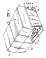
- Figure 1 is a perspective view of a plurality of interconnected modular refrigeration units in accordance with the present invention
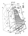
- FIG. 2 is a part cut-away perspective view of one modular refrigeration unit in accordance with the invention.
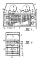
- Figure 3 is a part sectional, side elevational view of the modular unit of Figure 2,
- Figure 4 is a front elevational view, with the front panel removed, of the modular unit of Figure 2,
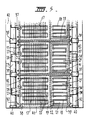
- Figure 5 is a cross-sectional plan view of several interconnected modular units in accordance with the invention.
- Figure 6 is a side elevational, part cross-sectional view of a further embodiment of the invention.
- a refrigeration system for use in an air conditioning installation comprises a series of modules 12 arranged in face-to-face relation.
- each module comprises a housing 14 on which is mounted two sealed unit refrigeration compressors 16.
- the housing 14 is formed of a bottom wall 42, side walls 41, a front wall 38, a rear wall 39 and a top wall 43.
- the housing 14 is divided into two compartments 19 and 21 separated by the partition 22.
- Compartment 19 contains a pair of evaporator coils 17, one for each compressor 16, and compartment 21 contains two condenser coils 18.
- An appropriate refrigerant expansion device (not shown) is connected between the respective evaporator and condenser of each refrigeration circuit, in a known manner.
- the compartments 19 and 21 define separate fluid flow passages which serve to carry separate flows of heat exchange fluid, for example water, in heat exchange relation with the evaporator coils 17 and the condenser coils 18.
- Baffles shown generally at 20, act to direct the flow of heat exchange fluid into intimate contact with the evaporator coils 17 while similar baffles 25 in compartment 21 act in a similar manner with regard to the condenser fluid flow.
- the heat exchange fluid i.e. water, which is to be cooled by the evaporator coils 17, is supplied to the compartment 19 by a header pipe 23 mounted on the front wall 38 of the housing 14 by bracket 24.
- the header pipe 23 has an opening 26 which communicates with an inlet tube 27 extending from the compartment 19.
- Cooled water is taken from compartment 19 through the lower header pipe 28 on the front wall 38 of the housing 14.
- the lower header pipe 28 has an opening 29, similar to opening 26, which communicates with an outlet tube 31.
- Header pipes 32 and 33 are mounted on the rear wall 39 of the housing 14 on brackets 30 and communicate with the compartment 21 by similar openings and tubes 34 and 36, respectively.
- the header pipe 33 conveys cooling water to the condenser coils 18 in compartment 21, the cooling water being removed through the header pipe 32.
- Each of the header pipes 23, 28, 32 and 33 are of a length enabling end-to-end connection with corresponding header pipes of adjacent modules 12 to form a common series of fluid manifolds.
- a coupling generally indicated at 35 such as that known by the trade mark VICTAULIC, is used to form fluid tight connections between the pipe ends.
- End caps 40 are used to seal the ends of the header pipes of the last module 12 of the assembly while appropriate fluid supply and return lines (not shown) are connected to the header pipes of the first module 12.
- Pipes 37 for conveying refrigerant between the compressors 16, condenser and evaporator coils 18, 17, respectively, extend down and through the front and rear walls 38 and 39 of the housing 14 to the respective coils.
- the side walls 41 on each side of the housing 14 are removable to give access to the compartments 19 and 21.
- the side walls are sealed against the housing bottom wall 42, the top wall 43 on which the compressors 16 are mounted, the partition 22 and the front and rear walls 38 and 39 to ensure that the compartments 19 and 21 are fluid tight.
- the evaporator coils 17 and the chiller water flow passages can be incorporated in a series of heat exchange plates which define the separate passageways for the respective fluids, thus obviating the need to provide a fluid tight compartment. Such plates are known in the art and are not described herein in detail.
- the top wall 43 of the housing 14 has mounted along the rear edge thereof an electrical bus bar 46 to which the compressors 16 are electrically connected.
- the bus bar 46 has appropriate connections 47 at each end to enable the bus bars of adjacent units to be interconnected to provide continuity of electrical power supply to each unit.
- top cover 51 is provided over the compressors 16.
- the top cover 51 is removable without removing the respective module 12 from the assembly to facilitate service and maintenance.
- Removable front and rear cover plates 56 and 57, respectively, are also provided on the housing 14.
- each module 12 comprises a separate refrigeration unit comprising two refrigeration circuits.
- the refrigeration circuits of each unit are, essentially, independent of those of each of the other modules, with each circuit including its own control means in order to deactuate the refrigeration unit in the event of an overload or other malfunction occurring in that unit.
- the control means includes an electrical control panel 48 mounted on the top wall 43 of the housing 14.
- the control panel 48 receives signals from sensors (not shown) associated with operation of the refrigeration units and transmits those signals through electrical connections 44 on the front of the housing 14 to a master control panel located on one of the modules 12 in the system, preferably an end module 12A.
- the master control panel houses the electrical control circuits for the control of the assembly of the modules 12 in accordance with the desired operation or control of the air conditioning installation whereby the cooling effect of the system (or the heating effect if the refrigeration units are acting in a reverse cycle mode) meets the instantaneous requirements of the air conditioning installation.
- the control circuits are operative to actuate only one or some of the modules 12 (depending on the load) with other units being brought into operation as the load increases.
- the control circuits are operative to automatically switch, at predetermined intervals, the order in which the modules 12 are brought into operation in order to substantially equalize the usage of the individual modules over a prolonged period of time.
- the control circuits may include memory circuits which maintain a constant record of the hours of operation of each module 12, the information being used to ensure substantial equalization of usage of the individual modules over a period of time.
- a simple microprocessor can be used to control the progressive switching functions and to match operation of the refrigeration system to the load requirements of the air conditioning installation to which the system is connected.
- the modular construction described permits additional slave modules 12 to be added to the assembly in order to increase the capacity of the referigeration system resulting from changes in load criteria of the air conditioning installation.
- that module may be shut down by the control circuits, while permitting continued operation of the other modules.
- the defective module may be repaired in situ while the system is in operation, or the defective module may be removed from the assembly for repair, a spare module being incorporated in the assembly to replace the removed, defective module or the assembly being permitted to operate without a replacement.
- the header pipes 23, 28, 32 and 33 of the modules 12 on each side of that to be removed are connected together by temporary pipe connections to maintain the heat exchange fluid circuits. Similar temporary electrical connections are also made.
- the housing 14 has a single compartment 19 for the evaporator coil 17 while the condenser coil 18 is located in an air cooling chamber 52 located above the compressor 16.
- Fans 53 draw air through the chamber 52 to cool the finned condenser coil 18.
- an evaporative condenser is used and for this purpose water sprays 54 (shown in dotted lines) spray water over the condenser coil 18.
- a refrigeration system formed in accordance with the present invention utilizing a number of modules 12 assembled together to form a single unit will have a reliability related to the reliability of the individual modules 12, which is substantially better than the reliability of a single refrigeration unit of equivalent output.
- the reliability is further enhanced, in accordance with the invention, by the continued operation of other modules of an assembly if one module is shut down for repair or maintenance.
- a system of increased capacity can be obtained in accordance with the invention simply by adding additional modules, as required, to take account of any increase in load resulting from a building extension or the like.
- header pipes to form common manifolds for supply and return of heat exchange fluid facilitates interconnection of the separate refrigeration units and allows modular construction of identical units which can be mass-produced for relatively less cost than fabricated units.
- the modular units are readily assembled into complete units of any desired capacity.
- the refrigeration circuits may be adapted for reverse cycle operation, if desired.
- the refrigeration system of the invention can be used for purposes other than air conditioning installations.
- the modular system is particularly useful for cool storage, cool rooms and freezer rooms in food processing and handling industries and in any other area requiring the use of relatively large capacity refrigeration.
Landscapes
- Engineering & Computer Science (AREA)
- Physics & Mathematics (AREA)
- Mechanical Engineering (AREA)
- Thermal Sciences (AREA)
- General Engineering & Computer Science (AREA)
- Devices That Are Associated With Refrigeration Equipment (AREA)
- Other Air-Conditioning Systems (AREA)
- Compression-Type Refrigeration Machines With Reversible Cycles (AREA)
- Cooling Or The Like Of Electrical Apparatus (AREA)
Claims (14)
- Kühlsystem zum Übertragen von Wärme von einem Fluid an ein anderes, mit einer Vielzahl von im wesentlichen identischen modularen Kühleinheiten (12), die zur Bildung eines Systemaufbaues zusammenfügbar sind, wobei jede Einheit (12) ein Gehäuse (14) für wenigstens einen Kühlkreis mit einem Kompressor (16), einem Verdampfer (17) und einem Kondensator (18), ferner ein erstes Fluiddurchflußmittel für den Durchfluß eines ersten Fluids unter Wärmeaustausch mit dem Verdampfer (17) und ein zweites Fluiddurchflußmittel für den Durchfluß eines zweiten Fluids unter Wärmeaustausch mit dem Kondensator (18), und ferner Mittel zum Fördern des ersten Fluids zum ersten Fluiddurchflußmittel und zweite Fluidzuführmittel zum Zuführen des zweiten Fluids zum zweiten Fluiddurchflußmittel aufweist, dadurch gekennzeichnet, daß die Mittel zum Fördern des ersten Fluids zum ersten Fluiddurchflußmittel ein Paar Sammelrohre (23,28), die sich längs der Einheit erstrecken und in Fluidverbindung mit dem ersten Fluiddurchflußmittel sind, und lösbare Verbindungsmittel (35), die benachbarte Enden der Sammelrohre benachbarter Einheiten miteinander verbinden, aufweisen, wodurch die miteinander verbundenen Sammelrohre (23,28) eine einheitliche erste Fluidzuführung und Rücklauf-Verteiler für den Aufbau unter Parallelschalten der Verdampfer (17) jeder Einheit (12) bilden.
- Kühlsystem nach Anspruch 1, dadurch gekennzeichnet, daß ein Paar zweiter Sammelrohre (32,33) sich längs jeder Einheit (12) erstreckt und mit dem zweiten Fluiddurchflußmittel zum Zuführen des zweiten Fluids in Verbindung ist.
- Kühlsystem nach Anspruch 1 oder 2, dadurch gekennzeichnet, daß jede modulare Einheit (12) zwei Kühlkreisläufe aufweist und daß das erste Fluiddurchflußmittel das erste Fluid in Wärmeaustauscherkontakt mit den zwei Verdampfern (17) der beiden Kreisläufe leitet.
- Kühlsystem nach Anspruch 3, daduruch gekennzeichnet, daß die getrennten Kondensatoren (18) der beiden Kreisläufe jeder Einheit (12) im zweiten Fluiddurchflußmittel parallel miteinander verbunden sind.
- Kühlsystem nach einem der vorhergehenden Ansprüche, dadurch gekennzeichnet, daß das erste Fluid Wasser ist.
- Kühlsystem nach einem der vorhergehenden Ansprüche, dadurch gekennzeichnet, daß das zweite Fluid Luft ist.
- Kühlystem nach Anspruch 1, dadurch gekennzeichnet, daß ein Paar Kompressoren (16) am Gehäuse (14) befestigt sind, wobei Kühlrohre durch die Gehäusewand zum Verdampfer (17) und zum Kondensator (18) der betreffenden Kühlkreisläufe führen und in Wärmeaustauschverbindung mit dem ersten bzw. zweiten Fluid sind.
- Kühlsystem nach Anspruch 1, dadurch gekennzeichnet, daß das Gehäuse (14) einen ersten Abschnitt (19), der den Verdampfer (17) enthält, und einen zweiten Abschnitt (21), der den Kondensator (18) enthält, aufweist.
- Kühlsystem nach Anspruch 1, dadurch gekennzeichnet, daß das Paar Sammelrohre eine Fluidzuführleitung und eine Fluidrücklaufleitung aufweist, die durch Leitungen mit dem ersten Fluiddurchflußmittel verbunden ist, daß die Zuführ- und die Rücklaufleitung jeweils mit fluiddichten lösbaren Kupplungen (35) verbunden sind, die deren Enden mit der Zuführ- bzw. Rücklaufleitung benachbarter Einheiten oder mit einer Hauptzuführleitung und einer Hauptrücklaufleitung im Falle einer Endeinheit des Aufbaues verbinden.
- Kühlsystem nach einem der vorhergehenden Ansprüche, dadurch gekennzeichnet, daß das zweite Fluid Wasser ist.
- Kühlsystem nach Anspruch 1, dadurch gekennzeichnet, daß der Kompressor (16) elektrisch betrieben ist und daß das Gehäuse (14) eine elektrische Sammelschiene mit lösbaren Verbindungen trägt, um die Sammelschienen benachbarter Einheiten des Aufbaues miteinander zu verbinden und dadurch eine durchgehende Spannungszuführung zu allen Einheiten des Aufbaues vorzusehen.
- Kühlsystem nach Anspruch 1, dadurch gekennzeichnet, daß eine Steuervorrichtung für den Aufbau zum Steuern der Betätigung jeder Einheit vorgesehen ist und daß die Steuervorrichtung derart betreibbar ist, daß eine aufeinanderfolgende schrittweise Zuschaltung der modularen Einheiten (12) des Aufbaues bei Erhöhung der angeforderten Belastung bewirkt ist.
- Kühlsystem nach Anspruch 12, dadurch gekennzeichnet, daß die Folge in der Zuschaltung der modularen Einheiten (12) sich in periodischen Intervallen automatisch ändert, um alle modularen Einheiten über eine bestimmte Zeitdauer hinweg im wesentlichen gleichmäßig zu verwenden.
- Kühlsystem nach Anspruch 12, dadurch gekennzeichnet, daß die Steuervorrichtung an jeder modularen Einheit (l2) Sensoren, um eine Überlast oder Fehlfunktion zu erfassen, und Mittel zum Unterbrechen des Betriebes jeder einzelnen modularen Einheit des Aufbaues aufgrund einer erfaßten Fehlfunktion oder zum Zuschalten einer sich nicht im Betrieb befindlichen Einheit des Aufbaues aufgrund einer erfaßten Überlast aufweist.
Applications Claiming Priority (4)
| Application Number | Priority Date | Filing Date | Title |
|---|---|---|---|
| AUPG619084 | 1984-07-24 | ||
| AU6190/84 | 1984-07-24 | ||
| AUPG740984 | 1984-09-28 | ||
| AU7409/84 | 1984-09-28 |
Publications (3)
| Publication Number | Publication Date |
|---|---|
| EP0190167A1 EP0190167A1 (de) | 1986-08-13 |
| EP0190167A4 EP0190167A4 (de) | 1987-08-05 |
| EP0190167B1 true EP0190167B1 (de) | 1991-03-13 |
Family
ID=25642832
Family Applications (1)
| Application Number | Title | Priority Date | Filing Date |
|---|---|---|---|
| EP85903189A Expired - Lifetime EP0190167B1 (de) | 1984-07-24 | 1985-07-16 | Modulares kühlsystem |
Country Status (23)
| Country | Link |
|---|---|
| US (1) | US4852362A (de) |
| EP (1) | EP0190167B1 (de) |
| JP (1) | JPH0812023B2 (de) |
| KR (1) | KR940001585B1 (de) |
| AR (1) | AR241957A1 (de) |
| AT (1) | ATE61656T1 (de) |
| AU (1) | AU589132B2 (de) |
| BR (1) | BR8506838A (de) |
| CA (1) | CA1280599C (de) |
| DE (1) | DE3582152D1 (de) |
| DK (1) | DK163262C (de) |
| EG (1) | EG17918A (de) |
| ES (1) | ES8608143A1 (de) |
| FI (1) | FI81195C (de) |
| HK (1) | HK9692A (de) |
| IN (1) | IN165547B (de) |
| MA (1) | MA20493A1 (de) |
| NO (1) | NO163465C (de) |
| NZ (1) | NZ212762A (de) |
| PH (1) | PH24213A (de) |
| SA (1) | SA90110071B1 (de) |
| SG (1) | SG9392G (de) |
| WO (1) | WO1986000977A1 (de) |
Families Citing this family (51)
| Publication number | Priority date | Publication date | Assignee | Title |
|---|---|---|---|---|
| IT1186300B (it) * | 1985-05-03 | 1987-11-18 | Bruno Bernardi | Unita' modulare per il trattamento a freddo o a caldo di fluidi in genere |
| EP0344351A1 (de) * | 1988-06-03 | 1989-12-06 | VIA Gesellschaft für Verfahrenstechnik mbH | Gas-Kältemittel-Wärmetauscher, insbesondere für Drucklufttrockner |
| FR2644232A1 (fr) * | 1989-03-08 | 1990-09-14 | Thermic Froid | Systeme de refrigeration et agencement de magasin a grande surface |
| SE8903385L (sv) * | 1989-10-13 | 1991-04-14 | Ivt Ind | Vaermepumpanlaeggning med koeldmediekretsen anordnad som en utbytbar enhet samt anordning foer genomfoerande av enhetsbyte |
| US5117271A (en) * | 1990-12-07 | 1992-05-26 | International Business Machines Corporation | Low capacitance bipolar junction transistor and fabrication process therfor |
| US5277036A (en) * | 1993-01-21 | 1994-01-11 | Unico, Inc. | Modular air conditioning system with adjustable capacity |
| DE4411813A1 (de) * | 1994-04-07 | 1995-10-12 | Stulz Gmbh | Verfahren zum Klimatisieren von Containern und Klimagerät zur Durchführung des Verfahrens |
| US5570585A (en) * | 1994-10-03 | 1996-11-05 | Vaynberg; Mikhail | Universal cooling system automatically configured to operate in compound or single compressor mode |
| JP3324686B2 (ja) * | 1997-07-14 | 2002-09-17 | エスエムシー株式会社 | 恒温液循環装置 |
| US6098657A (en) * | 1998-06-09 | 2000-08-08 | Multistack, Inc. | In-line fluid flow trap for modular refrigeration systems |
| US6209330B1 (en) * | 1999-05-17 | 2001-04-03 | Caterpillar Inc. | Modular air handling system and method for providing cooling |
| US6848267B2 (en) * | 2002-07-26 | 2005-02-01 | Tas, Ltd. | Packaged chilling systems for building air conditioning and process cooling |
| US6272867B1 (en) | 1999-09-22 | 2001-08-14 | The Coca-Cola Company | Apparatus using stirling cooler system and methods of use |
| US6532749B2 (en) | 1999-09-22 | 2003-03-18 | The Coca-Cola Company | Stirling-based heating and cooling device |
| US6481216B2 (en) * | 1999-09-22 | 2002-11-19 | The Coca Cola Company | Modular eutectic-based refrigeration system |
| US6481228B1 (en) * | 2001-08-23 | 2002-11-19 | Industrial Technology Research Institute | Air conditioning module for room partition unit |
| US6893087B2 (en) * | 2002-11-18 | 2005-05-17 | Stearns Inc. | All terrain vehicle seat cushion |
| US7131284B2 (en) * | 2003-08-19 | 2006-11-07 | Electrolux Home Products, Inc. | Automatic defrost controller including air damper control |
| US6988538B2 (en) * | 2004-01-22 | 2006-01-24 | Hussmann Corporation | Microchannel condenser assembly |
| US20060130517A1 (en) * | 2004-12-22 | 2006-06-22 | Hussmann Corporation | Microchannnel evaporator assembly |
| MX2008016457A (es) * | 2006-06-19 | 2009-07-22 | Hydrokool Llc | Metodo, sistema y aparato para una planta central modular. |
| ITBA20060068A1 (it) * | 2006-12-13 | 2008-06-14 | Giuseppe Giovanni Renna | Gruppo frigorifero modulare |
| DE102007021885A1 (de) * | 2006-12-14 | 2008-06-26 | Glen Dimplex Deutschland Gmbh | Kühlgerät, Kühlmodul für ein Kühlgerät sowie Verfahren zur Reparatur eines Kühlgeräts |
| US8523643B1 (en) | 2007-06-14 | 2013-09-03 | Switch Communications Group LLC | Electronic equipment data center or co-location facility designs and methods of making and using the same |
| US20100287960A1 (en) * | 2008-01-31 | 2010-11-18 | Remo Meister | Modular Air-Conditioning System and Method for the Operation Thereof |
| US8973379B2 (en) * | 2008-07-25 | 2015-03-10 | Hill Phoenix, Inc. | Refrigeration control systems and methods for modular compact chiller units |
| CA2741684C (en) * | 2008-10-28 | 2013-05-21 | Trak International, Llc | High-efficiency heat pumps |
| ES2382968B1 (es) * | 2009-02-23 | 2013-04-26 | Climetal, S.A. | Condensador para aparatos de aire acondicionado |
| JP5386201B2 (ja) * | 2009-03-12 | 2014-01-15 | 三菱重工業株式会社 | ヒートポンプ装置 |
| EP2408668B1 (de) * | 2009-03-20 | 2015-08-12 | Axa Power Aps | Einheit zur luftvorbehandlung mit autonomen kühlmodulen |
| US20100263394A1 (en) * | 2009-04-17 | 2010-10-21 | Timothy Robert Ayres | Chiller assembly |
| ES2704446T3 (es) * | 2009-06-02 | 2019-03-18 | Schneider Electric It Corp | Unidad de tratamiento del aire de un contenedor y método de refrigeración |
| US9091451B2 (en) * | 2009-06-05 | 2015-07-28 | Hobart Brothers Company | Modular heating, ventilating, air conditioning, and refrigeration systems and methods |
| GB2473675B (en) * | 2009-09-22 | 2011-12-28 | Virtensys Ltd | Switching method |
| US9062887B2 (en) * | 2009-11-19 | 2015-06-23 | Hobart Brothers Company | Modular heating, ventilating, air conditioning, and refrigeration systems and methods |
| US8813512B2 (en) * | 2009-11-19 | 2014-08-26 | Hobart Brothers Company | Condenser assemblies for heating, ventilating, air conditioning, and refrigeration systems |
| US9677778B2 (en) | 2010-04-20 | 2017-06-13 | Climacool Corp. | Modular chiller unit with dedicated cooling and heating fluid circuits and system comprising a plurality of such units |
| US8899057B2 (en) | 2010-09-17 | 2014-12-02 | Hobart Brothers Company | Control systems and methods for modular heating, ventilating, air conditioning, and refrigeration systems |
| JP2012247168A (ja) * | 2011-05-31 | 2012-12-13 | Mitsubishi Electric Corp | 冷凍サイクル装置 |
| US9562708B2 (en) | 2012-12-03 | 2017-02-07 | Waterfurnace International, Inc. | Conduit module coupled with heating or cooling module |
| FI125774B (fi) | 2013-07-05 | 2016-02-15 | Timo Rautiainen | Ilmastointijärjestelmä |
| US9146045B2 (en) | 2013-08-07 | 2015-09-29 | Climacool Corp | Modular chiller system comprising interconnected flooded heat exchangers |
| WO2015026904A1 (en) * | 2013-08-22 | 2015-02-26 | Uop Llc | Refrigeration and compressor modules |
| EP3165849B1 (de) * | 2014-07-02 | 2023-04-26 | Mitsubishi Electric Corporation | Wärmequellenvorrichtung und wärmequellensystem mit der wärmequellenvorrichtung |
| CN107532805A (zh) * | 2015-04-21 | 2018-01-02 | 三菱电机株式会社 | 热源单元 |
| WO2016199238A1 (ja) * | 2015-06-10 | 2016-12-15 | 三菱電機株式会社 | 冷凍サイクル装置及び冷凍サイクルシステム |
| WO2017216926A1 (ja) * | 2016-06-16 | 2017-12-21 | 東芝キヤリア株式会社 | 冷凍サイクル装置 |
| WO2018022503A1 (en) * | 2016-07-25 | 2018-02-01 | Jacobi Robert W | Modular system for heating and/or cooling requirements |
| JP2018054257A (ja) * | 2016-09-30 | 2018-04-05 | ダイキン工業株式会社 | 熱交換ユニット |
| US11326830B2 (en) | 2019-03-22 | 2022-05-10 | Robert W. Jacobi | Multiple module modular systems for refrigeration |
| EP3861259A4 (de) * | 2019-12-10 | 2022-04-20 | Dehumidified Air Solutions, Inc. | Verdichterwand |
Family Cites Families (40)
| Publication number | Priority date | Publication date | Assignee | Title |
|---|---|---|---|---|
| US411476A (en) * | 1889-09-24 | Radiator | ||
| US3067592A (en) * | 1962-12-11 | figure | ||
| US88964A (en) * | 1869-04-13 | Improved blast-heating apparatus for smelting-furnaces | ||
| US849369A (en) * | 1906-03-03 | 1907-04-09 | Charles B Clark | Gas-cooler. |
| US2177602A (en) * | 1936-05-11 | 1939-10-24 | Honeywell Regulator Co | Air conditioning system |
| GB522911A (en) * | 1937-12-23 | 1940-07-01 | British Thomson Houston Co Ltd | Improvements in and relating to fluid cooling systems |
| GB699782A (en) * | 1951-10-19 | 1953-11-18 | Arthur Markwell | Improvements in and relating to condenser coil assemblies for use in refrigeration apparatus |
| US2759708A (en) * | 1953-11-02 | 1956-08-21 | Drying Systems Inc | Air to air heat pump apparatus |
| US2935857A (en) * | 1957-02-19 | 1960-05-10 | Alden I Mcfarlan | Air conditioning |
| US3151672A (en) * | 1961-10-30 | 1964-10-06 | Westinghouse Air Brake Co | Water cooled air cooler |
| GB1065330A (en) * | 1963-12-23 | 1967-04-12 | Lamb Weston Inc | Air cooling system for below freezing temperatures |
| US3240027A (en) * | 1964-07-01 | 1966-03-15 | William K Kyle | Controls for multi-compressor refrigeration systems |
| US3555251A (en) * | 1967-12-06 | 1971-01-12 | Honeywell Inc | Optimizing system for a plurality of temperature conditioning apparatuses |
| US3526274A (en) * | 1968-06-04 | 1970-09-01 | Du Pont | Cross flow box cooler unit |
| US3705622A (en) * | 1970-07-07 | 1972-12-12 | Dunham Bush Inc | Cleanable tube within a tube heat exchanger and method of forming modular headers therefor |
| JPS5249862Y2 (de) * | 1973-07-27 | 1977-11-12 | ||
| JPS5075754U (de) * | 1973-11-14 | 1975-07-02 | ||
| DK30474A (de) * | 1974-01-21 | 1975-09-15 | M Fordsmand | |
| US3996759A (en) * | 1975-11-03 | 1976-12-14 | Milton Meckler | Environment assisted hydronic heat pump system |
| US3999160A (en) * | 1975-12-05 | 1976-12-21 | Mcdonnell Richard M | Modular traffic signal apparatus |
| GB1553217A (en) * | 1976-08-31 | 1979-09-26 | Isovel Ltd | Refrigerating apparatus |
| DE2659480A1 (de) * | 1976-12-30 | 1978-07-06 | Kueppersbusch | Heizeinrichtung mit einem waermepumpenaggregat |
| US4122893A (en) * | 1977-03-07 | 1978-10-31 | American Air Filter Company, Inc. | Air conditioning system |
| US4112921A (en) * | 1977-04-25 | 1978-09-12 | Calmac Manufacturing Corporation | Method and system for utilizing a flexible tubing solar collector |
| JPS5437944A (en) * | 1977-08-31 | 1979-03-20 | Mitsubishi Electric Corp | Apparatuses operation controller |
| US4210957A (en) * | 1978-05-08 | 1980-07-01 | Honeywell Inc. | Operating optimization for plural parallel connected chillers |
| FR2502762A1 (fr) * | 1978-08-11 | 1982-10-01 | Zundel Daniel | Pompe de chaleur a elements modulaires et a fonctions multiples |
| JPS5572770A (en) * | 1978-11-27 | 1980-05-31 | Hitachi Ltd | Cooling system |
| FI791079A (fi) * | 1979-04-02 | 1980-10-03 | Valmet Oy | Pao utnyttjande av en vaermepump sig grundande foerfarande vid tillvaratagande av vaerme |
| DE3013518A1 (de) * | 1980-04-08 | 1981-10-15 | MITEC Moderne Industrietechnik GmbH, 8012 Ottobrunn | Waermepumpe oder kaeltemaschine |
| FR2484065A1 (fr) * | 1980-06-06 | 1981-12-11 | Helpac Applic Thermodyn Solair | Perfectionnements aux pompes a chaleur |
| JPS5716766A (en) * | 1980-07-04 | 1982-01-28 | Mitsubishi Electric Corp | Airconditioner |
| SU987332A1 (ru) * | 1981-04-03 | 1983-01-07 | Научно-Исследовательский Институт Санитарной Техники И Оборудования Зданий И Сооружений | Установка дл производства тепла и холода |
| JPS57166439A (en) * | 1981-04-07 | 1982-10-13 | Mitsubishi Electric Corp | Cooling and heating device |
| DE3116624C2 (de) * | 1981-04-27 | 1985-08-29 | Daimler-Benz Ag, 7000 Stuttgart | Energieversorgungssystem für Wärme und Elektrizität |
| JPS5840465A (ja) * | 1981-09-03 | 1983-03-09 | 松下精工株式会社 | 空冷式冷凍機 |
| US4402190A (en) * | 1982-05-11 | 1983-09-06 | Reid Samuel I | Apparatus and method for heating and chilling concrete batch water |
| DE3228934C2 (de) * | 1982-08-03 | 1985-03-28 | Adolf H. 7410 Reutlingen Kirn | Vorrichtung zum Kühlen von Flüssigkeit |
| US4483152A (en) * | 1983-07-18 | 1984-11-20 | Butler Manufacturing Company | Multiple chiller control method |
| US4535602A (en) * | 1983-10-12 | 1985-08-20 | Richard H. Alsenz | Shift logic control apparatus for unequal capacity compressors in a refrigeration system |
-
1985
- 1985-07-16 WO PCT/AU1985/000155 patent/WO1986000977A1/en active IP Right Grant
- 1985-07-16 NZ NZ212762A patent/NZ212762A/en unknown
- 1985-07-16 AT AT85903189T patent/ATE61656T1/de not_active IP Right Cessation
- 1985-07-16 KR KR1019860700164A patent/KR940001585B1/ko not_active IP Right Cessation
- 1985-07-16 AU AU46010/85A patent/AU589132B2/en not_active Ceased
- 1985-07-16 EP EP85903189A patent/EP0190167B1/de not_active Expired - Lifetime
- 1985-07-16 BR BR8506838A patent/BR8506838A/pt not_active IP Right Cessation
- 1985-07-16 DE DE8585903189T patent/DE3582152D1/de not_active Expired - Lifetime
- 1985-07-16 JP JP60503202A patent/JPH0812023B2/ja not_active Expired - Lifetime
- 1985-07-16 US US06/849,499 patent/US4852362A/en not_active Expired - Lifetime
- 1985-07-19 PH PH32542A patent/PH24213A/en unknown
- 1985-07-19 IN IN561/MAS/85A patent/IN165547B/en unknown
- 1985-07-22 CA CA000487243A patent/CA1280599C/en not_active Expired - Lifetime
- 1985-07-23 ES ES85545468A patent/ES8608143A1/es not_active Expired
- 1985-07-23 AR AR85301069A patent/AR241957A1/es active
- 1985-07-24 EG EG435/85A patent/EG17918A/xx active
- 1985-07-24 MA MA20719A patent/MA20493A1/fr unknown
-
1986
- 1986-03-14 FI FI861054A patent/FI81195C/fi not_active IP Right Cessation
- 1986-03-21 DK DK131486A patent/DK163262C/da not_active IP Right Cessation
- 1986-03-21 NO NO86861133A patent/NO163465C/no unknown
-
1990
- 1990-09-18 SA SA90110071A patent/SA90110071B1/ar unknown
-
1992
- 1992-01-30 HK HK96/92A patent/HK9692A/xx not_active IP Right Cessation
- 1992-01-31 SG SG93/92A patent/SG9392G/en unknown
Also Published As
Similar Documents
| Publication | Publication Date | Title |
|---|---|---|
| EP0190167B1 (de) | Modulares kühlsystem | |
| US20100132390A1 (en) | Variable four pipe heatpump chiller | |
| US8627674B2 (en) | Modular outboard heat exchanger air conditioning system | |
| US11867426B2 (en) | System and methods utilizing fluid coolers and chillers to perform in-series heat rejection and trim cooling | |
| US6792766B2 (en) | Zone demand controlled dual air conditioning system and controller therefor | |
| KR0133024B1 (ko) | 냉매냉각장치 결합용 보충냉각 시스템 | |
| US5701750A (en) | Zone demand controlled dual heat pump system and controller therefor | |
| US20090173096A1 (en) | Methodology for converting existing packaged rooftop air conditioning units to be served from a centralized water cooled refrigeration and/or heat pump system | |
| US7216494B2 (en) | Supermarket refrigeration system and associated methods | |
| EP3567996A1 (de) | Modularer kühler für rechenzentren | |
| CN112368528B (zh) | 与空冷冷冻机集成的模块式水侧节能器 | |
| US20150198353A1 (en) | Modular outboard heat exchanger air conditioning system | |
| EP0508245B1 (de) | Kombiniertes Heiz- und Kühlsystem | |
| SU1558311A3 (ru) | Система охлаждени | |
| CN113133289A (zh) | 一种室内空调末端及机房空调 | |
| CN112616291A (zh) | 数据中心装置 | |
| EP1861664A1 (de) | Integriertes system zur erzeugung von hitze und kälte zur gleichzeitigen verwendung mittels kühl- und heizeinheiten | |
| CN1013991B (zh) | 组合式制冷系统 | |
| CN215188009U (zh) | 一种带空调末端的机柜及机房复合热管空调 | |
| EP1612491A2 (de) | Flüssigkeitskühler für Klimaanlagen | |
| FI120752B (fi) | Kiinteistötekniikkajärjestelmä | |
| AU5157390A (en) | Improved zonal control of air conditioning system |
Legal Events
| Date | Code | Title | Description |
|---|---|---|---|
| PUAI | Public reference made under article 153(3) epc to a published international application that has entered the european phase |
Free format text: ORIGINAL CODE: 0009012 |
|
| AK | Designated contracting states |
Kind code of ref document: A1 Designated state(s): AT BE CH DE FR GB IT LI LU NL SE |
|
| 17P | Request for examination filed |
Effective date: 19860812 |
|
| A4 | Supplementary search report drawn up and despatched |
Effective date: 19870805 |
|
| 17Q | First examination report despatched |
Effective date: 19880629 |
|
| ITF | It: translation for a ep patent filed |
Owner name: FIAMMENGHI - DOMENIGHETTI |
|
| DIN1 | Information on inventor provided before grant (deleted) | ||
| RAP1 | Party data changed (applicant data changed or rights of an application transferred) |
Owner name: MULTISTACK INTERNATIONAL PTY. LTD. |
|
| GRAA | (expected) grant |
Free format text: ORIGINAL CODE: 0009210 |
|
| AK | Designated contracting states |
Kind code of ref document: B1 Designated state(s): AT BE CH DE FR GB IT LI LU NL SE |
|
| REF | Corresponds to: |
Ref document number: 61656 Country of ref document: AT Date of ref document: 19910315 Kind code of ref document: T |
|
| REF | Corresponds to: |
Ref document number: 3582152 Country of ref document: DE Date of ref document: 19910418 |
|
| ET | Fr: translation filed | ||
| PG25 | Lapsed in a contracting state [announced via postgrant information from national office to epo] |
Ref country code: LU Free format text: LAPSE BECAUSE OF NON-PAYMENT OF DUE FEES Effective date: 19910731 |
|
| PLBE | No opposition filed within time limit |
Free format text: ORIGINAL CODE: 0009261 |
|
| STAA | Information on the status of an ep patent application or granted ep patent |
Free format text: STATUS: NO OPPOSITION FILED WITHIN TIME LIMIT |
|
| 26N | No opposition filed | ||
| EAL | Se: european patent in force in sweden |
Ref document number: 85903189.0 |
|
| PGFP | Annual fee paid to national office [announced via postgrant information from national office to epo] |
Ref country code: SE Payment date: 19980727 Year of fee payment: 14 |
|
| PGFP | Annual fee paid to national office [announced via postgrant information from national office to epo] |
Ref country code: NL Payment date: 19980728 Year of fee payment: 14 Ref country code: DE Payment date: 19980728 Year of fee payment: 14 |
|
| PGFP | Annual fee paid to national office [announced via postgrant information from national office to epo] |
Ref country code: AT Payment date: 19980730 Year of fee payment: 14 |
|
| PGFP | Annual fee paid to national office [announced via postgrant information from national office to epo] |
Ref country code: BE Payment date: 19980804 Year of fee payment: 14 |
|
| PGFP | Annual fee paid to national office [announced via postgrant information from national office to epo] |
Ref country code: CH Payment date: 19980805 Year of fee payment: 14 |
|
| PG25 | Lapsed in a contracting state [announced via postgrant information from national office to epo] |
Ref country code: AT Free format text: LAPSE BECAUSE OF NON-PAYMENT OF DUE FEES Effective date: 19990716 |
|
| PG25 | Lapsed in a contracting state [announced via postgrant information from national office to epo] |
Ref country code: SE Free format text: THE PATENT HAS BEEN ANNULLED BY A DECISION OF A NATIONAL AUTHORITY Effective date: 19990717 |
|
| PG25 | Lapsed in a contracting state [announced via postgrant information from national office to epo] |
Ref country code: LI Free format text: LAPSE BECAUSE OF NON-PAYMENT OF DUE FEES Effective date: 19990731 Ref country code: CH Free format text: LAPSE BECAUSE OF NON-PAYMENT OF DUE FEES Effective date: 19990731 Ref country code: BE Free format text: LAPSE BECAUSE OF NON-PAYMENT OF DUE FEES Effective date: 19990731 |
|
| BERE | Be: lapsed |
Owner name: MULTISTACK INTERNATIONAL PTY. LTD Effective date: 19990731 |
|
| PG25 | Lapsed in a contracting state [announced via postgrant information from national office to epo] |
Ref country code: NL Free format text: LAPSE BECAUSE OF NON-PAYMENT OF DUE FEES Effective date: 20000201 |
|
| REG | Reference to a national code |
Ref country code: CH Ref legal event code: PL |
|
| EUG | Se: european patent has lapsed |
Ref document number: 85903189.0 |
|
| NLV4 | Nl: lapsed or anulled due to non-payment of the annual fee |
Effective date: 20000201 |
|
| PG25 | Lapsed in a contracting state [announced via postgrant information from national office to epo] |
Ref country code: DE Free format text: LAPSE BECAUSE OF NON-PAYMENT OF DUE FEES Effective date: 20000503 |
|
| PGFP | Annual fee paid to national office [announced via postgrant information from national office to epo] |
Ref country code: FR Payment date: 20000731 Year of fee payment: 16 |
|
| PGFP | Annual fee paid to national office [announced via postgrant information from national office to epo] |
Ref country code: GB Payment date: 20000814 Year of fee payment: 16 |
|
| PG25 | Lapsed in a contracting state [announced via postgrant information from national office to epo] |
Ref country code: GB Free format text: LAPSE BECAUSE OF NON-PAYMENT OF DUE FEES Effective date: 20010716 |
|
| GBPC | Gb: european patent ceased through non-payment of renewal fee |
Effective date: 20010716 |
|
| PG25 | Lapsed in a contracting state [announced via postgrant information from national office to epo] |
Ref country code: FR Free format text: LAPSE BECAUSE OF NON-PAYMENT OF DUE FEES Effective date: 20020329 |
|
| REG | Reference to a national code |
Ref country code: FR Ref legal event code: ST |