EP0189543A2 - Mehrzelliger elektrischer Akkumulator mit kombinierter Abgastrocken- und Flammschutzvorrichtung - Google Patents
Mehrzelliger elektrischer Akkumulator mit kombinierter Abgastrocken- und Flammschutzvorrichtung Download PDFInfo
- Publication number
- EP0189543A2 EP0189543A2 EP85114831A EP85114831A EP0189543A2 EP 0189543 A2 EP0189543 A2 EP 0189543A2 EP 85114831 A EP85114831 A EP 85114831A EP 85114831 A EP85114831 A EP 85114831A EP 0189543 A2 EP0189543 A2 EP 0189543A2
- Authority
- EP
- European Patent Office
- Prior art keywords
- gas
- accumulator according
- flame retardant
- frit
- gases
- Prior art date
- Legal status (The legal status is an assumption and is not a legal conclusion. Google has not performed a legal analysis and makes no representation as to the accuracy of the status listed.)
- Granted
Links
Images
Classifications
-
- H—ELECTRICITY
- H01—ELECTRIC ELEMENTS
- H01M—PROCESSES OR MEANS, e.g. BATTERIES, FOR THE DIRECT CONVERSION OF CHEMICAL ENERGY INTO ELECTRICAL ENERGY
- H01M50/00—Constructional details or processes of manufacture of the non-active parts of electrochemical cells other than fuel cells, e.g. hybrid cells
- H01M50/30—Arrangements for facilitating escape of gases
- H01M50/392—Arrangements for facilitating escape of gases with means for neutralising or absorbing electrolyte; with means for preventing leakage of electrolyte through vent holes
-
- H—ELECTRICITY
- H01—ELECTRIC ELEMENTS
- H01M—PROCESSES OR MEANS, e.g. BATTERIES, FOR THE DIRECT CONVERSION OF CHEMICAL ENERGY INTO ELECTRICAL ENERGY
- H01M10/00—Secondary cells; Manufacture thereof
- H01M10/42—Methods or arrangements for servicing or maintenance of secondary cells or secondary half-cells
- H01M10/52—Removing gases inside the secondary cell, e.g. by absorption
-
- H—ELECTRICITY
- H01—ELECTRIC ELEMENTS
- H01M—PROCESSES OR MEANS, e.g. BATTERIES, FOR THE DIRECT CONVERSION OF CHEMICAL ENERGY INTO ELECTRICAL ENERGY
- H01M50/00—Constructional details or processes of manufacture of the non-active parts of electrochemical cells other than fuel cells, e.g. hybrid cells
- H01M50/30—Arrangements for facilitating escape of gases
-
- H—ELECTRICITY
- H01—ELECTRIC ELEMENTS
- H01M—PROCESSES OR MEANS, e.g. BATTERIES, FOR THE DIRECT CONVERSION OF CHEMICAL ENERGY INTO ELECTRICAL ENERGY
- H01M50/00—Constructional details or processes of manufacture of the non-active parts of electrochemical cells other than fuel cells, e.g. hybrid cells
- H01M50/30—Arrangements for facilitating escape of gases
- H01M50/383—Flame arresting or ignition-preventing means
-
- H—ELECTRICITY
- H01—ELECTRIC ELEMENTS
- H01M—PROCESSES OR MEANS, e.g. BATTERIES, FOR THE DIRECT CONVERSION OF CHEMICAL ENERGY INTO ELECTRICAL ENERGY
- H01M50/00—Constructional details or processes of manufacture of the non-active parts of electrochemical cells other than fuel cells, e.g. hybrid cells
- H01M50/30—Arrangements for facilitating escape of gases
- H01M50/394—Gas-pervious parts or elements
-
- Y—GENERAL TAGGING OF NEW TECHNOLOGICAL DEVELOPMENTS; GENERAL TAGGING OF CROSS-SECTIONAL TECHNOLOGIES SPANNING OVER SEVERAL SECTIONS OF THE IPC; TECHNICAL SUBJECTS COVERED BY FORMER USPC CROSS-REFERENCE ART COLLECTIONS [XRACs] AND DIGESTS
- Y02—TECHNOLOGIES OR APPLICATIONS FOR MITIGATION OR ADAPTATION AGAINST CLIMATE CHANGE
- Y02E—REDUCTION OF GREENHOUSE GAS [GHG] EMISSIONS, RELATED TO ENERGY GENERATION, TRANSMISSION OR DISTRIBUTION
- Y02E60/00—Enabling technologies; Technologies with a potential or indirect contribution to GHG emissions mitigation
- Y02E60/10—Energy storage using batteries
-
- Y—GENERAL TAGGING OF NEW TECHNOLOGICAL DEVELOPMENTS; GENERAL TAGGING OF CROSS-SECTIONAL TECHNOLOGIES SPANNING OVER SEVERAL SECTIONS OF THE IPC; TECHNICAL SUBJECTS COVERED BY FORMER USPC CROSS-REFERENCE ART COLLECTIONS [XRACs] AND DIGESTS
- Y02—TECHNOLOGIES OR APPLICATIONS FOR MITIGATION OR ADAPTATION AGAINST CLIMATE CHANGE
- Y02P—CLIMATE CHANGE MITIGATION TECHNOLOGIES IN THE PRODUCTION OR PROCESSING OF GOODS
- Y02P70/00—Climate change mitigation technologies in the production process for final industrial or consumer products
- Y02P70/50—Manufacturing or production processes characterised by the final manufactured product
Definitions
- the invention relates to a multi-cell electric accumulator, in particular a starter battery in a block box, the individual cells of which are degassed via a common gas channel led through the block cover to the outside.
- each cell in a 6-cell battery, is provided with a ventilation opening and this in turn is assigned an individual, closed ventilation channel, which runs parallel to the channels of the other cells in the block cover and only on one side of the cover in all Channels common fine-pored filter piece with a downstream gas outlet chamber opens.
- Such a degassing system is suitable for preventing inflammation or explosions of the oxyhydrogen contained in the battery by ignition from the outside and also for such inflammations to spread from one cell to the other, with the disadvantage that the filter piece with electrolyte particles from the upper charge gases can become clogged.
- An example of another embodiment of a "central degassing" is the multi-cell battery known from DE-OS 23 58 417 called that comes closest to the type of accumulator according to the invention.
- the individual gas spaces of the cells can communicate with each other through small openings that are made in the cell partitions above the electrolyte level, or via a central tube with small openings that is laid through the partitions.
- the space above the electrolyte level represents a degassing chamber, the gas being discharged outside through a hose connection on the cover or through the above-mentioned pipe, which is only open at one end.
- the central degassing itself cannot prevent acid mist from being discharged with the battery gases.
- a compact starter battery used in vehicles would be more cumbersome to handle with a hose line that leads the fog away to a less endangered location.
- the frit in turn has the disadvantage that condensed moisture gradually clogs its pores, so that an inadmissibly high pressure builds up in the battery by blocking the gas outlet.
- the invention is therefore based on the task to make a multi-cell battery with a central degassing available in which an acid outlet Vietnamese.stattfindet, via a more - has seeds explosion protection, whereby ignition of the charging gases from outside of the battery which the ignition inwardly wear, be prevented, and in which the possibility of a gas jam is largely excluded.
- a major advantage of the invention is that all the necessary precautions for the safe functioning of a central degassing without significant space, z. B. in the outer area of the battery housing, so that the battery can be used at its original place of use without retooling, for example to another bracket.
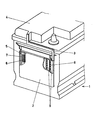
- the figure shows a starter battery 1 according to the invention with a container 2 arranged in a bay-like manner on a side wall of the block box.
- the outline of the housing and thus the compactness of the battery is hardly touched by the container. It receives the gases collected under the block cover 4 via a connecting channel 3 and vents through a gas outlet 5 after the gases have first been dried during their passage and then passed through a flame retardant device 6.
- the inside of the container is divided into at least two successive rooms, viewed in the direction of flow, of which the first room contains means for acid separation and collection with the aim of removing moisture, while the second room is intended for receiving flame retardants, the actual protective device A flame extinguishing chamber 7 is also connected on the gas outlet side.
- the gas dehumidified in this way can now flow onto the flame protection device 6 in the second room, which is preferably a frit made of sintered porous plastic, without the risk of the pore system becoming wet through to sealing and with the undesirable consequence of a gas jam.
- the so-called flame extinguishing chamber 7 is located between the frit 6 and the gau outlet 5.
- the charging gases catch the flame front that rushes backwards and cause the gases to abruptly burn off.
- the formation of a standing flame on the outside of the frit, associated with the risk of burning is prevented, and the spread of the ignition to the connecting channel and into the battery interior is no longer possible.
- the aforementioned liquid supply which is in the inevitable path of the gases, functions as a flame arrester and even ensures that the flame is extinguished if the mechanism described last should fail.
- the flame retardant device consists of a combination of the frit with a porous metal body as a means for rapid heat dissipation, which is arranged upstream of the frit on its gas inlet side.
- the agent can be a porous sintered material or a bed of metallic particles, e.g. B. metal chips. Foam metal, metal fleece or steel wool are also suitable. If appropriate, each of these agents can also be used instead of the frit in the form of a corresponding shaped body.
- the pore size of the metal body is appropriately such that the moisture still present in the gas condensed out by surface adsorption, resulting in a gas drying effect.
- the container finally offers itself in an advantageous manner for accommodating a gas sensor according to German patent application P 34 14 664, if it is placed at a point where the gas flowing through is already freed of acid particles and dehumidified.
- this sensor is a temperature-sensitive electronic component, for example a commercially available NTC or PTC resistor, which is superficial with a material that catalyzes the hydrogen recombination, for. B. a PTFE-bonded palladium / activated carbon mixture is coated.
- the resistance reacts to the temperature rise, which is associated with the gas recombination on the catalytic converter, as soon as the accumulator gases develop at the end of a charge with the stoichiometric composition of the oxyhydrogen gas.
- the change in resistance then provides an electrical signal to indicate the fully charged state or to switch off the charging current.
Landscapes
- Chemical & Material Sciences (AREA)
- Chemical Kinetics & Catalysis (AREA)
- Electrochemistry (AREA)
- General Chemical & Material Sciences (AREA)
- Engineering & Computer Science (AREA)
- Manufacturing & Machinery (AREA)
- Gas Exhaust Devices For Batteries (AREA)
- Secondary Cells (AREA)
- Air Bags (AREA)
Abstract
Description
- Die Erfindung betrifft einen mehrzelligen elektrischen Akkumulator, insbesondere eine Starterbatterie in einem Blockkasten, dessen einzelne Zellen über einen gemeinsamen, durch den Blockdeckel nach draußen geführten Gaskanal entgasen.
- Die Betriebsumstände solcher Akkumulatoren verbieten es oft, Gase aus einzelnen Zellen frei austreten zu lassen. Entweder liegen dafür Sicherheitsgründe vor oder einfach der Wunsch nach einer gesamtheitlichen Gasentsorgung der Batterie mit Ableitung der Gase. zu einer definierten Stelle.
- Nach dem deutschen Gebrauchsmuster 8003 869 ist bei einer 6-zelligen Akkumulatorenbatterie jede Zelle mit einer Entlüftungsöffnung versehen und dieser wiederum ein individueller, geschlossener Entlüftungskanal zugeordnet, welcher parallel zu den Kanälen der anderen Zellen im Blockdeckel verläuft und erst an einer Seite des Deckels in ein allen Kanälen gemeinsames feinporiges Filterstück mit einer nachgeschalteten Gasauslaßkammer einmündet.
- Ein solches Entgasungssystem ist geeignet, Entzündungen bzw. Explosionen des in der Batterie enthaltenen Knallgases durch Zündung von außen und auch ein übergreifen derartiger Entzündungen von einer Zelle zur anderen zu verhindern, mit dem Nachteil, daß sich das Filterstuck mit Elektrolytpartikelchen aus den Oberladegasen zusetzen kann.
- Als ein Beispiel für eine andere Ausführungsform einer "Zentralentgasung" sei die aus der DE-OS 23 58 417 bekannte Mehrzellen-Batterie genannt, die gattungsmäßig dem erfindungsgemäßen Akkumulator am nächsten kommt. Dort können die einzelnen Gasräume der Zellen durch kleine öffnungen, die in die Zellentrennwände oberhalb des Elektrolytspiegels eingebracht sind, oder über ein zentrales, durch die Trennwände hindurchverlegtes Rohr mit kleinen öffnungen zu jeder Zelle untereinander kommunizieren. In beiden Fällen stellt der oberhalb des Elektrolytspiegels vorhandene Raum eine Entgasungskammer dar, wobei die Gasabführung nach draußen durch einen Schlauchanschluß am Deckel bzw. durch das genannte, nur an einem Ende offene Rohr erfolgt.
- Die zentrale Entgasung an sich kann nicht verhindern, daß mit den Batteriegasen Säurenebel ausgetragen werden. Mit einer Schlauchleitung, welche die Nebel zu einem weniger gefährdeten Ort wegführt, wäre eine in Fahrzeugen verwendete kompakte Starterbatterie jedoch umständlicher zu handhaben. Außerdem ist die Gefahr, daß durch in der Nähe der Batterie gebildete Funken oder Flammen Knallgasexplosionen ausgelöst.werden, gerade wegen des massierten Gasangebots an der zentralen Austrittsstelle eher vergrößert, weshalb eine Abschließung derselben durch eine Flammenschutzvorrichtung, z. B. mittels einer Fritte, zu den bereits bekannten und praktizierten Maßnahmen zählt. Die Fritte ihrerseits ist mit dem Nachteil behaftet, daß kondensierte Feuchtigkeit ihre Poren allmählich verstopft, so daß durch Blockierung des Gasaustritts sich in der Batterie ein unzulässig hoher Druck aufbaut.
- Der Erfindung liegt daher die Aufgabe zugrunde, einen mehrzelligen Akkumulator mit zentraler Entgasungseinrichtung verfügbar zu machen, bei welchem ein Säureaustritt nicht.stattfindet, der über einen wirk- samen Explosionsschutz verfügt, wobei auch Zündungen der Ladegase von außerhalb der Batterie, welche die Entflammung nach innen tragen, verhindert werden, und bei welchem die Möglichkeit eines Gasstaus weitgehend ausgeschlossen ist.
- Die Aufgabe wird erfindungsgemäß mit den im kennzeichnenden Teil des Anspruchs 1 angegebenen Maßnahmen gelöst.
- Ein wesentlicher Vorteil der Erfindung liegt darin, daß alle für das gefahrlose Funktionieren einer Zentralentgasung notwendigen Vorkehrungen ohne nennenswerten Platzbedarf, z. B. im Außenbereich des Batteriegehäuses, getroffen werden, so daß die Batterie an ihrem ursprünglichen Einsatzort ohne Umrüsten, etwa auf eine andere Halterung, weiter verwendet werden kann.
- Die Erfindung wird im folgenden anhand einer Figur näher erläutert.
- Die Figur zeigt eine erfindungsgemäße Starterbatterie 1 mit einem erkerartig an einer Seitenwand des Blockkastens angeordneten Behältnis 2. Wie ersichtlich, wird der Gehäuseumriß und damit die Kompaktheit der Batterie durch das Behältnis kaum berührt. Es mimmt über einen Verbindungskanal 3 die unter dem Blockdeckel 4 gesammelten Gase auf und entlüftet durch einen Gasaustritt 5, nachdem die Gase bei ihrem Durch- ' gang zunächst eine Trocknung erfahren und danach eine Flammschutzvorrichtung 6 passiert haben. Entsprechend ist das Behältnis innen zumindest in zwei hintereinanderliegende Räume, in Durchstömungsrichtung gesehen, aufgeteilt, von denen der erste Raum Mittel zur Säureabscheidung und Sammlung mit dem Ziel der Feuchtigkeitsentfernung enthält, während der zweite Raum zur Aufnahme von Flammschutzmitteln vorgesehen ist, wobei sich der eigentlichen Schutzeinrichtung gasaustrittsseitig noch eine Flammenlöschkammer 7 anschließt.
- Als eine wirksame Maßnahme zum Trocknen von Gasen hat sich das wiederholte Umlenken des Gasstromes an Hindernissen erwiesen. Die mitgeführten Flüssigkeitströpfchen vermögen aufgrund ihrer Trägheit dem raschen Richtungswechsel nicht zu folgen, pranen ab und schlagen sich am Boden des Behältnisses nieder. Geeignete Mittel zur Feuchtigkeitsentfernung stellen daher im vorderen Teil des Behältnisses quer in den Gasraum gestellte Wände 8, die auch perforiert sein können, dar. Das Behältnis weist dadurch gegebenenfalls eine ganze Serie von Kammern 9 auf. Die Wände können erfindungsgemäß ersetzt oder ergänzt werden durch eine Flüssigkeitsvorlage mit einer nicht verdunstenden Flüssigkeit, die andererseits keine zu hohe Viskosität besitzen darf, damit das Gas leicht hindurchperlt. Dabei werden Säurepartikel, soweit sie nicht bereits von den Spritzfängern in den Zellen zurückgehalten wurden, abgetrennt.
- Das hierdurch entfeuchtete Gas kann nunmehr die Flammschutzvorrichtung 6 im zweiten Raum anströmen, die vorzugsweise eine Fritte aus sinterporösem Kunststoff ist, ohne daß Gefahr einer Durchnässung des Porensystems bis zum Dichtsetzen und mit der unerwünschten Folge eines Gasstaus besteht.
- Zwischen der Fritte 6 und dem Gausaustritt 5 befindet sich erfindungsgemäß die sogenannte Flammenlöschkammer 7. Diese hält schädliche äussere Einflüsse von der Fritte fern; ihre eigentliche Funktion, für welche ihr Volumen ebenso wie die Gasaustrittsöffnung entsprechend ' ausgelegt sind, ist jedoch die, daß sie bei einer äußeren Zündung. der Ladegase die batteriewärts zurückeilende Flammenfront auffängt und die Gase zu einem schlagartigen Abbrennen veranlaßt. Auf diese Weise wird die Ausbildung einer stehenden Flamme an der Frittenaußenseite, verbunden mit der Gefahr des Durchbrennens, verhindert, und die Ausbreitung der Zündung bis zum Verbindungskanal und in das Batterieinnere ist nicht mehr möglich. Dabeit tritt außerdem die erwähnte, im Zwangsweg der Gase liegende Flüssigkeitsvorlage als Flammsperre in Funktion und gewährleistet sogar dann einen Flammenabbruch, wenn der zuletzt beschriebene Mechanismus versagen sollte.
- Besonders günstig ist es daher, wenn die Flammschutzvorrichtung aus einer Kombination der Fritte mit einem porösen Metallkörper als Mittel zur raschen Wärmeableitung besteht, welcher der Fritte an ihrer Gaseintrittsseite.vorgelagert ist. Das Mittel kann ein poröses Sintermaterial oder eine in das Behältnis eingebrachte Schüttung metallischer Partikel, z. B. Metallspäne, sein. Geeignet sind auch ein Schaummetall, ein Metallvlies oder Stahlwolle. Gegebenenfalls ist jedes dieser Mittel auch ersatzweise anstelle der Fritte in Gestalt eines entspechenden Formkörpers verwendbar. Die Porengröße der Metallkörper ist zweckmäßig so bemessen, daß die im Gas noch vorhandene Feuchtigkeit durch Oberflächenadsorption auskondensiert und sich so eine gastrocknende Wirkung ergibt.
- Das Behältnis bietet sich schließlich in vorteilhafter Weise zur Unterbringung eines Gassensors gemäß deutscher Patentanmeldung P 34 14 664 an,.wenn man diesen an einer Stelle plaziert, wo das hindurchströmende Gas bereits von Säurepartikeln befreit und entfeuchtet ist. Bei. diesem Sensor handelt es sich um ein temperaturempfindliches elektronisches Bauelement, beispielsweise einen handelsüblichen NTC- oder PTC-Widerstand, der oberflächlich mit einem die Wasserstoffrekombination katalysierenden Material, z. B. eine PTFE-gebundene Palladium/Aktivkohlemischung, beschichtet ist. Der Widerstand reagiert auf den Temperaturanstieg, welcher mit der Gasrekombination am Katalysator einhergeht, sobald die Akkumulatorgase am Ende einer Ladung sich mit der stöchiometrischen Zusammensetzung des Knallgases entwickeln. Die Widerstandsänderung liefert dann ein elektrisches Signal zur Anzeige des Vollladezustandes bzw. zum Abschalten des Ladestromes.
Claims (10)
Priority Applications (1)
| Application Number | Priority Date | Filing Date | Title |
|---|---|---|---|
| AT85114831T ATE66544T1 (de) | 1985-01-30 | 1985-11-22 | Mehrzelliger elektrischer akkumulator mit kombinierter abgastrocken- und flammschutzvorrichtung. |
Applications Claiming Priority (2)
| Application Number | Priority Date | Filing Date | Title |
|---|---|---|---|
| DE3503014 | 1985-01-30 | ||
| DE19853503014 DE3503014A1 (de) | 1985-01-30 | 1985-01-30 | Mehrzelliger elektrischer akkumulator mit kombinierter abgastrocken- und flammschutzvorrichtung |
Publications (3)
| Publication Number | Publication Date |
|---|---|
| EP0189543A2 true EP0189543A2 (de) | 1986-08-06 |
| EP0189543A3 EP0189543A3 (en) | 1986-11-20 |
| EP0189543B1 EP0189543B1 (de) | 1991-08-21 |
Family
ID=6261120
Family Applications (1)
| Application Number | Title | Priority Date | Filing Date |
|---|---|---|---|
| EP85114831A Expired - Lifetime EP0189543B1 (de) | 1985-01-30 | 1985-11-22 | Mehrzelliger elektrischer Akkumulator mit kombinierter Abgastrocken- und Flammschutzvorrichtung |
Country Status (6)
| Country | Link |
|---|---|
| US (1) | US4678726A (de) |
| EP (1) | EP0189543B1 (de) |
| JP (1) | JPS61176055A (de) |
| AT (1) | ATE66544T1 (de) |
| CA (1) | CA1265190A (de) |
| DE (2) | DE3503014A1 (de) |
Cited By (4)
| Publication number | Priority date | Publication date | Assignee | Title |
|---|---|---|---|---|
| AU603463B2 (en) * | 1987-09-01 | 1990-11-15 | Globe-Union Inc. | Method and apparatus for the preparation and installation of battery explosion attenuation material |
| EP0952619A1 (de) * | 1998-04-20 | 1999-10-27 | Accumulatorenwerke Hoppecke Carl Zoellner & Sohn GmbH & Co. KG | Rekombinationsvorrichtung zur katalytischen Rekombination von in Akkumulatoren entstehendem Wasserstoff und Sauerstoff zu Wasser |
| LU90461B1 (fr) * | 1999-10-15 | 2001-04-17 | Accumalux S A | Couvercle pour batterie |
| WO2013128226A1 (en) * | 2012-03-02 | 2013-09-06 | Johnson Controls Autobatterie Gmbh & Co. Kgaa | Venting device for an electrochemical battery and battery with a venting device |
Families Citing this family (10)
| Publication number | Priority date | Publication date | Assignee | Title |
|---|---|---|---|---|
| US6068945A (en) * | 1996-09-26 | 2000-05-30 | Akkumulatorenfabrick Moll Gmbh & Co. Kg | Battery |
| FR2841386B1 (fr) * | 2002-06-20 | 2004-10-15 | Cit Alcatel | Batterie a securite amelioree |
| DE102009050878A1 (de) * | 2009-10-27 | 2011-04-28 | Carl Freudenberg Kg | Batterie mit einem außerhalb des Batteriegehäuses angeordneten Filterelement |
| DE102012219379A1 (de) | 2012-10-24 | 2014-04-24 | Robert Bosch Gmbh | Batterie mit einer Entgasungsöffnung sowie ein Kraftfahrzeug mit der erfindungsgemäßen Batterie |
| DE102018202947A1 (de) * | 2018-02-27 | 2019-08-29 | Bayerische Motoren Werke Aktiengesellschaft | Schutzvorrichtung für ein Kraftfahrzeugbatteriegehäuse, Traktionsbatterie und Kraftfahrzeug |
| US11942653B2 (en) | 2020-03-04 | 2024-03-26 | Donaldson Company, Inc. | Housing with integrated spark arrestor |
| DE102020109634B3 (de) * | 2020-04-07 | 2021-06-10 | Bayerische Motoren Werke Aktiengesellschaft | Batterie mit Desaktivierungseinrichtung sowie Kraftfahrzeug |
| WO2022133780A1 (en) * | 2020-12-23 | 2022-06-30 | 3M Innovative Properties Company | Battery module and process for making same |
| CN117546353A (zh) * | 2021-07-13 | 2024-02-09 | 松下知识产权经营株式会社 | 电子设备 |
| DE102022102826B4 (de) | 2022-02-07 | 2025-09-11 | Audi Aktiengesellschaft | Batteriegehäuse für einen Energiespeicher, Energiespeicher für ein Kraftfahrzeug und Verfahren zum Abführen eines Gas-Partikel-Gemischs aus einem Batteriegehäuse |
Family Cites Families (15)
| Publication number | Priority date | Publication date | Assignee | Title |
|---|---|---|---|---|
| GB1095499A (de) * | ||||
| FR429332A (fr) * | 1911-03-31 | 1911-09-20 | Georges Roisset | Accumulateur électrique |
| FR860921A (fr) * | 1939-07-10 | 1941-01-28 | Neutralisateur pour accumulateurs électriques | |
| US2331450A (en) * | 1939-11-28 | 1943-10-12 | Sonotone Corp | Rechargeable storage battery |
| GB791139A (en) * | 1954-07-16 | 1958-02-26 | Peter Josef Moll | Improvements relating to electric batteries |
| US3102220A (en) * | 1959-05-29 | 1963-08-27 | Miranda Corp | Secondary battery catalyst device with temperature responsive means |
| US4117205A (en) * | 1976-12-29 | 1978-09-26 | Shin-Kobe Electric Machinery Co., Ltd. | Electric storage battery |
| US4087592A (en) * | 1977-04-19 | 1978-05-02 | Japan Storage Battery Company Limited | Wafer supply structure for liquid storage battery |
| JPS5748289Y2 (de) * | 1978-03-04 | 1982-10-22 | ||
| IT7948327A0 (it) * | 1978-03-15 | 1979-03-13 | Chloride Group Ltd | Perfezionamento nei tappi di riempimento per elementi di batterie di accumulatori |
| JPS606071B2 (ja) * | 1979-01-20 | 1985-02-15 | 古河電池株式会社 | モノブロツク蓄電池の蓋装置並に製造法 |
| DE3045480A1 (de) * | 1980-12-03 | 1982-07-01 | Varta Batterie Ag, 3000 Hannover | Verschlussanordnung fuer bleiakkumulatoren |
| US4400450A (en) * | 1981-07-27 | 1983-08-23 | Allied Corporation | Battery vent |
| US4447508A (en) * | 1981-10-13 | 1984-05-08 | Allied Corporation | Reduced maintenance explosion damage resistant storage battery |
| US4463069A (en) * | 1983-03-24 | 1984-07-31 | General Motors Corporation | Battery venting system |
-
1985
- 1985-01-30 DE DE19853503014 patent/DE3503014A1/de not_active Withdrawn
- 1985-11-22 EP EP85114831A patent/EP0189543B1/de not_active Expired - Lifetime
- 1985-11-22 AT AT85114831T patent/ATE66544T1/de not_active IP Right Cessation
- 1985-11-22 DE DE8585114831T patent/DE3583859D1/de not_active Expired - Lifetime
-
1986
- 1986-01-22 US US06/821,497 patent/US4678726A/en not_active Expired - Fee Related
- 1986-01-29 CA CA000500561A patent/CA1265190A/en not_active Expired - Lifetime
- 1986-01-30 JP JP61016988A patent/JPS61176055A/ja active Pending
Cited By (8)
| Publication number | Priority date | Publication date | Assignee | Title |
|---|---|---|---|---|
| AU603463B2 (en) * | 1987-09-01 | 1990-11-15 | Globe-Union Inc. | Method and apparatus for the preparation and installation of battery explosion attenuation material |
| EP0952619A1 (de) * | 1998-04-20 | 1999-10-27 | Accumulatorenwerke Hoppecke Carl Zoellner & Sohn GmbH & Co. KG | Rekombinationsvorrichtung zur katalytischen Rekombination von in Akkumulatoren entstehendem Wasserstoff und Sauerstoff zu Wasser |
| WO1999054944A1 (de) * | 1998-04-20 | 1999-10-28 | Accumulatorenwerke Hoppecke Carl Zoellner & Sohn Gmbh & Co. Kg | Rekombinationsvorrichtung zur katalytischen rekombination von in akkumulatoren entstehendem wasserstoff und sauerstoff zu wasser |
| US6254841B1 (en) | 1998-04-20 | 2001-07-03 | Accumulatorenwerke Hoppecke Carl Zoellner & Sohn Gmbh & Co. Kg | Recombination system for the catalytic recombination of hydrogen and oxygen, forming in storage batteries, into water |
| LU90461B1 (fr) * | 1999-10-15 | 2001-04-17 | Accumalux S A | Couvercle pour batterie |
| WO2001029911A1 (fr) * | 1999-10-15 | 2001-04-26 | Accumalux S.A. | Couvercle pour batterie comportant un systeme de ventilation |
| WO2013128226A1 (en) * | 2012-03-02 | 2013-09-06 | Johnson Controls Autobatterie Gmbh & Co. Kgaa | Venting device for an electrochemical battery and battery with a venting device |
| US9508972B2 (en) | 2012-03-02 | 2016-11-29 | Johnson Controls Technology Company | Venting device for an electrochemical battery and battery with a venting device |
Also Published As
| Publication number | Publication date |
|---|---|
| JPS61176055A (ja) | 1986-08-07 |
| EP0189543B1 (de) | 1991-08-21 |
| US4678726A (en) | 1987-07-07 |
| CA1265190A (en) | 1990-01-30 |
| DE3503014A1 (de) | 1986-07-31 |
| DE3583859D1 (de) | 1991-09-26 |
| EP0189543A3 (en) | 1986-11-20 |
| ATE66544T1 (de) | 1991-09-15 |
Similar Documents
| Publication | Publication Date | Title |
|---|---|---|
| EP0189543B1 (de) | Mehrzelliger elektrischer Akkumulator mit kombinierter Abgastrocken- und Flammschutzvorrichtung | |
| EP2394330B1 (de) | Batteriemodul | |
| DE2402718C2 (de) | Belüftungsverschluß für Akkumulatoren | |
| DE102021000029A1 (de) | Mehrschichtiges Schutzelement für eine Batterie | |
| DE69309908T2 (de) | Elektrostatischer zwei-stufen filter | |
| DE102021114113A1 (de) | Batterieeinheit, batteriemodul und batteriepack | |
| DE102014012568B4 (de) | Akkumulatorvorrichtung | |
| DE3000474C2 (de) | Gehäuseförmige Abdeckung für einen einteiligen Akkumulator | |
| EP0305822B2 (de) | Mehrzellige Batterie mit in den Batteriedeckel integrierter zentraler Entgasungsleitung | |
| DE69212705T2 (de) | Vorrichtung zur Abführung von Abgasen, die innenliegend von Akkumulatorbatterien gebildet werden | |
| EP0570703B1 (de) | Akkumulator mit im Deckel Befindlichem Entgasungssystem | |
| EP0590357B1 (de) | Mehrzelliger Bleiakkumulator | |
| DE3843297C2 (de) | Ionisationsrauchmelder | |
| EP0053732B1 (de) | Verschlussanordnung für Bleiakkumulatoren | |
| DE9407172U1 (de) | Akkumulator mit Entgasungskanal | |
| EP0639862B1 (de) | Mehrzellige Batterie | |
| DE2452750C2 (de) | Tragbares Sprühgerät | |
| EP3709383B1 (de) | Batteriegestell | |
| DE102015007411A1 (de) | Batteriegehäuse, Batterie und Fahrzeug mit zumindest einer Batterie | |
| DE3018372C2 (de) | ||
| DE3802748C2 (de) | ||
| DE102014017868A1 (de) | System mit Vorrichtung zur Trocknung von Gas für Batteriegehäuse | |
| DE3309497A1 (de) | Gasfilter | |
| DE102021129671A1 (de) | Filtermodul, Anlage zur Filterung von Stäuben und Verfahren zur Abtrennung von Stäuben aus einem Gasstrom | |
| DE2254896A1 (de) | Mehrfachverschluss mit belueftung fuer akkumulator-fuelloeffnungen |
Legal Events
| Date | Code | Title | Description |
|---|---|---|---|
| PUAI | Public reference made under article 153(3) epc to a published international application that has entered the european phase |
Free format text: ORIGINAL CODE: 0009012 |
|
| AK | Designated contracting states |
Kind code of ref document: A2 Designated state(s): AT DE FR GB SE |
|
| PUAL | Search report despatched |
Free format text: ORIGINAL CODE: 0009013 |
|
| AK | Designated contracting states |
Kind code of ref document: A3 Designated state(s): AT DE FR GB SE |
|
| 17P | Request for examination filed |
Effective date: 19870127 |
|
| 17Q | First examination report despatched |
Effective date: 19880108 |
|
| GRAA | (expected) grant |
Free format text: ORIGINAL CODE: 0009210 |
|
| AK | Designated contracting states |
Kind code of ref document: B1 Designated state(s): AT DE FR GB SE |
|
| PG25 | Lapsed in a contracting state [announced via postgrant information from national office to epo] |
Ref country code: SE Effective date: 19910821 Ref country code: GB Effective date: 19910821 |
|
| REF | Corresponds to: |
Ref document number: 66544 Country of ref document: AT Date of ref document: 19910915 Kind code of ref document: T |
|
| REF | Corresponds to: |
Ref document number: 3583859 Country of ref document: DE Date of ref document: 19910926 |
|
| PG25 | Lapsed in a contracting state [announced via postgrant information from national office to epo] |
Ref country code: AT Effective date: 19911122 |
|
| EN | Fr: translation not filed | ||
| PG25 | Lapsed in a contracting state [announced via postgrant information from national office to epo] |
Ref country code: FR Effective date: 19920110 |
|
| GBV | Gb: ep patent (uk) treated as always having been void in accordance with gb section 77(7)/1977 [no translation filed] | ||
| PLBE | No opposition filed within time limit |
Free format text: ORIGINAL CODE: 0009261 |
|
| STAA | Information on the status of an ep patent application or granted ep patent |
Free format text: STATUS: NO OPPOSITION FILED WITHIN TIME LIMIT |
|
| 26N | No opposition filed | ||
| REG | Reference to a national code |
Ref country code: FR Ref legal event code: ST |
|
| PGFP | Annual fee paid to national office [announced via postgrant information from national office to epo] |
Ref country code: DE Payment date: 20011102 Year of fee payment: 17 |
|
| PG25 | Lapsed in a contracting state [announced via postgrant information from national office to epo] |
Ref country code: DE Free format text: LAPSE BECAUSE OF NON-PAYMENT OF DUE FEES Effective date: 20030603 |