EP0187599A1 - Druckmittelangetriebene Vorrichtung zum Messen und Ausführen von Arbeiten in einem abgelenkten Bohrloch während der Injektion oder der Förderung - Google Patents
Druckmittelangetriebene Vorrichtung zum Messen und Ausführen von Arbeiten in einem abgelenkten Bohrloch während der Injektion oder der Förderung Download PDFInfo
- Publication number
- EP0187599A1 EP0187599A1 EP85402626A EP85402626A EP0187599A1 EP 0187599 A1 EP0187599 A1 EP 0187599A1 EP 85402626 A EP85402626 A EP 85402626A EP 85402626 A EP85402626 A EP 85402626A EP 0187599 A1 EP0187599 A1 EP 0187599A1
- Authority
- EP
- European Patent Office
- Prior art keywords
- extension
- opening
- casing
- fluid
- production
- Prior art date
- Legal status (The legal status is an assumption and is not a legal conclusion. Google has not performed a legal analysis and makes no representation as to the accuracy of the status listed.)
- Granted
Links
Images


Classifications
-
- E—FIXED CONSTRUCTIONS
- E21—EARTH DRILLING; MINING
- E21B—EARTH DRILLING, e.g. DEEP DRILLING; OBTAINING OIL, GAS, WATER, SOLUBLE OR MELTABLE MATERIALS OR A SLURRY OF MINERALS FROM WELLS
- E21B23/00—Apparatus for displacing, setting, locking, releasing, or removing tools, packers or the like in the boreholes or wells
- E21B23/14—Apparatus for displacing, setting, locking, releasing, or removing tools, packers or the like in the boreholes or wells for displacing a cable or cable-operated tool, e.g. for logging or perforating operations in deviated wells
-
- E—FIXED CONSTRUCTIONS
- E21—EARTH DRILLING; MINING
- E21B—EARTH DRILLING, e.g. DEEP DRILLING; OBTAINING OIL, GAS, WATER, SOLUBLE OR MELTABLE MATERIALS OR A SLURRY OF MINERALS FROM WELLS
- E21B23/00—Apparatus for displacing, setting, locking, releasing, or removing tools, packers or the like in the boreholes or wells
- E21B23/08—Introducing or running tools by fluid pressure, e.g. through-the-flow-line tool systems
- E21B23/10—Tools specially adapted therefor
-
- E—FIXED CONSTRUCTIONS
- E21—EARTH DRILLING; MINING
- E21B—EARTH DRILLING, e.g. DEEP DRILLING; OBTAINING OIL, GAS, WATER, SOLUBLE OR MELTABLE MATERIALS OR A SLURRY OF MINERALS FROM WELLS
- E21B33/00—Sealing or packing boreholes or wells
- E21B33/02—Surface sealing or packing
- E21B33/03—Well heads; Setting-up thereof
- E21B33/068—Well heads; Setting-up thereof having provision for introducing objects or fluids into, or removing objects from, wells
- E21B33/072—Well heads; Setting-up thereof having provision for introducing objects or fluids into, or removing objects from, wells for cable-operated tools
Definitions
- the present invention relates to a device propelled by hydraulic pressure allowing measurements and interventions during injection or production in a deviated well.
- deflected well is meant here both the well deflected wells and those strongly deflected and which require pumping of the equipment to reach the producing area.
- the invention is particularly applicable when it is a question of carrying out measurements, for example of pressure and flow, at the level of geological formations, or any other intervention in a well and when it is a question of highlighting , for example, the flow profile of the producing part of a deviated eruptive well.
- the measuring or intervention instrument can be, for example, a logging probe. It is either electrically connected to the surface by a logging cable, or not connected to the surface, benefiting in this case from an autonomous power supply and an information storage memory.
- the volume located above the locomotive is pressurized by pumping, so as to push the equipment (probe and extension ) in the deviated area of interest to the producer.
- the measurements are made during the pushing phase when the probe is in the production zone, or during the ascent phase. They can advantageously be repeated.
- the assembly of all the equipment is carried out by pulling on the cable. If the production tubing has a substantially constant internal diameter and since the linings ensure good sealing, it sometimes happens that a phenomenon of pistoning and therefore of suction of the fluid is observed, capable of creating pressure imbalances and displacements of fluid, leading to uncontrolled production.
- US Patent 2,122,697 also mentions a sensor lowered by circulation by means of pumping and which is then anchored to the bottom of the well via a deformable membrane and springs, while US Patent 3,104,714 relates to a tool. pumped fitted with an electric cable and which includes pads which will brake and prevent the tool from rising.
- the first step is to introduce all of the tools into a pressurized well.
- a device according to the present invention which can be used to carry out, during injection or fluid production operations, measurements or interventions in a deviated well passing through a geological formation, this well being fitted with casing.
- This device comprises at least one measuring or intervention instrument fixed to a first end of an extension, the other end of which constitutes the upper end, is provided with sealing members enabling the device to be propelled into said casing. under the effect of hydraulic pressure, the device being, moreover, connected to the surface by a flexible line such as an electric cable supplying the probe.
- the device according to the invention has a propulsion position in the casing and a measurement or intervention position and it includes means supporting said sealing members, said means being adapted on the one hand, to discover at least one opening. allowing the fluid to circulate all along the tube and the extension in said measurement or intervention position of the device and, on the other hand, to close said opening in said propulsion position.
- said means comprise two elongated elements, one of which is fixed to the upper part of the extension and has at least two openings located on either side of the sealing members and the other of which is movable, has at least one opening located above sealing members and can be moved by sliding, under the effect of a traction exerted on said cable, or by a remote-controlled member from the surface, for example a motor, from a first position corresponding to the closing of said openings up to a second position which uncovers said openings.
- said means comprise at the upper part of said extension a membrane delimiting an annular chamber of variable volume, this chamber being able to be connected to a source of auxiliary fluid under pressure to give said volume a value ensuring substantially the sealing and allowing propulsion by injection of fluid from the surface, said chamber can also be placed under vacuum to allow the flow of injection or production fluid in said casing, around said membrane and means for adjusting the pressure in said chamber.
- the invention is more particularly applicable when the wells crossing the geological formation are deviated by an angle such that the probe cannot descend by gravity and, for example, by an angle of more than 40 ° relative to the vertical.
- injection measurements can be made. Under these conditions, traction on the cable makes it possible to free the openings of the device according to the invention and the injected fluid can circulate.
- the measurements are carried out during the injection phase, preferably by reassembling the whole of the equipment (the opening therefore being maintained).
- the flow measurements for example, are made while the fluid is produced which will then be recovered on the surface.
- the uncovered opening has a cross section substantially equal to the cross section between the casing and the extension so as to minimize the pressure drops.
- the means supporting the sealing members include an anchoring on the flexible line at a point such that the length of said flexible line in the extension allows the opening to be discovered. It is, for example, at least equal to the length of the extension to which is added the length of the opening along the axis of the well.
- the upper element sliding relative to the lower element may include locking systems, for example electromechanical, remote controlled from the surface, in order to maintain the opening in the closed position during pumping, during the descent. of the equipment, or maintaining the opening in the open position, when raising the equipment and during the production and measurement phase.
- locking systems for example electromechanical, remote controlled from the surface
- the means for adjusting the pressure in the variable volume chamber may include a compensation chamber in communication, on the one hand, with the interior of the casing and, on the other hand, with the source of auxiliary fluid.
- the invention also relates to equipment usable for carrying out, during injection or fluid production operations, measurements or interventions in a well passing through a geological formation, this equipment comprising in combination a device as defined above and a remote controlled subsurface valve, through which said device can slide in the open position of this valve.
- Said valve may define with the surface an airlock of a length equal to the length of the device.
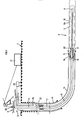
- FIG. 1 represents a well 1 equipped with a first casing 1a of internal diameter, for example equal to 40 cm, vertical from the surface 3 and which is deflected in its terminal part.
- Another casing 1b for example 24 cm, contained in the first casing, descended into the deviated part of the well, the space between the two casings being cemented.
- This tubing lb is extended by a third tubing 5 of about 18 cm in diameter which has holes 5a to recover the production of a horizontal drain 4.
- a tubing support lc provides the link with the tubing lb and the tubing 5, while that a seal ld is made between the casing 5 and the production casing 2 of approximately 8 cm, at the end of which there is a restriction or "nogo" 40.
- the extension 15 and the probe 8, for example, were pumped, that is to say pushed by a fluid (diesel for example) in the casing 2, thanks to a locomotive 16 from the surface.
- a control cabin controls the handling, lifting and pumping of fluids.
- a traction cable 6 (diameter for example 8 mm), driven by a winch 7, is connected to a probe support and to a standard type logging probe 8 (diameter 4.3 cm for example) which can be autonomous or connected by an electric cable to the surface, the latter can also be a towing cable.
- the traction cable also supports the extension elements.
- the logging probe 8 and its support are fixed either to the screwed elements of the "snubbing" or to the "coil tubing" (flexible tube wound on a coil) which constitute the extension 15, with a diameter close to that of the probe and of length, for example, between 100 and 500 meters and possibly connected to the surface by an electrical probe-surface connection provided either by a single connector at the probe, or by a multiplicity of connectors, each being arranged substantially in the vicinity of each element.
- the propulsion means, all of the screwed elements, the probe support and the logging probe preferably have a diameter less than the opening diameter of the valve.
- the device according to the invention illustrated in FIG. 2 At the upper end of the extension is the device according to the invention illustrated in FIG. 2, with the propulsion system 16 or locomotive comprising one or more sealing elements 17 (or cups) ensuring the sealing with the production tubing 2, this device being integral with cable 6.
- FIGS 2 and 3 show an advantageous embodiment of the device according to the invention.
- the upper element of the extension 15 has an extension 19 which can be screwed and of internal diameter substantially equal to that of the extension.
- the lower part of this extension is pierced with at least a first lateral opening 20 possibly allowing the passage of the fluid through the extension; its upper part is also pierced with at least a second lateral opening 21 through which the fluid is discharged towards the surface.
- Each of these openings is located on either side of the position of the locomotive 16. The role of these openings 20 and 21 can be reversed, if one works in injection.
- the movable element or sliding sleeve 22 comes to cap the extension 19.
- This sleeve has two openings 20a and 21a located on either side of the locomotive. It is integral with the cable 6 in its upper part and a pin 23 housed in a rotation wedge groove 24 allows only an axial displacement of the sliding jacket 22 when the cable 6 undergoes a traction from bottom to top.
- the cable 6 has been secured on the surface to the sliding jacket 22 at a lashing point 27, after taking the precaution of leaving a little slack to allow the displacement of the sliding jacket.
- the latter effectively comprises the sealing cups 17 of the locomotive 16. In the pumping position, it rests at 26 on the bottom stop 25 of the extension 19 of the extension and thereby obstructs the openings 20, 20a, 21 and 21a thus preventing any circulation of fluid.
- a pull of the cable causes the jacket to rise up to a stop provided by the pin 23 and the openings are released. The fluid can then flow.
- FIG. 3A illustrates another particularly advantageous embodiment in which the opening 20 through the element 19 remains permanently open, the sliding jacket 22 covering only the openings 21.
- the section of the fluid inlet or outlet openings is preferably substantially equal to the section of the annular space between the casing 2 and the extension 15, so as to minimize the pressure drop.
- the production tube comprises elements of decreasing diameter, for example three elements A, B, C (30, 31, 32) of respective diameters 0 A 3 ⁇ B and ⁇ C such that ⁇ A > ⁇ B > ⁇ C
- FIG. 1 illustrates the artificial airlock 11 and more particularly the subsurface valve 33 arranged on the production line 2. This valve ensures safety and equilibrium airlock during the assembly and disassembly phase of the probe and of the extension and of the device according to the invention, and the putting in of the airlock, during the descent and ascent phase of all the equipment.
- a manual remote control transmits energy from the surface to the valve 33, via either a hydraulic or gas-fired central 34 and a pipe 35, so as to open or close it at will during the various operating phases and especially so as to prevent any uncontrolled closure following an overpressure, which would cause the cable to break if the probe and extension were already engaged under the valve.
- the valve is also self-closing, so as to comply with current safety standards.
- a subsurface valve 33 is placed in advance on a casing of production 2 at a distance at least equal to the length between the wellhead and the end of the probe, or about 300 meters.
- This valve is permanently open, with control for closing, or it can be permanently closed, with control for opening. We close the valve.
- the airlock thus created is at atmospheric pressure. 0n successively introduces the measurement probe 8 attached to the cable 6, then the extension 15, element by element, and the propulsion system 16, 17 and 19 mounted on the device according to the invention.
- An electrical connection is possibly established by means of a bottom connector.
- the cable gland 36 is closed on the surface around the cable and the pressure is balanced on either side of the valve 33 and then it is opened by remote control from the surface.
- the extension and the probe are then in the production drain 4.
- the sliding jacket 22 is moved without touching the rest of the equipment, since the cable has a little slack inside the device .
- This operation allows the fluid to flow through the holes 5a of the production area and from there to the surface and to pass through the openings 20 and 21 thus released, the device according to the invention. Under these conditions, it is possible to carry out measurements, for example of flow rate, using the production tubing which was used to move the probe and the extension.
- the probe and extension can be moved by pushing or pulling on the cable.
- the measurements can then be stationary, or made continuously during the movement, so as to determine a profile of drain flow.
- the probe, extension and propulsion system assembly is reassembled without pistoning, since the sliding jacket is open and since the fluid can be transferred from the upper part to the lower part of the propulsion system.
- the assembly being reassembled above the subsurface valve 33, the latter is closed and the airlock defined above is purged.
- FIGS. 5 and 6 A variant of the device according to the invention which is particularly advantageous when the casing has variations in diameter is illustrated by FIGS. 5 and 6. It comprises an extension extension 19 fixed on the one hand to the cable 6 and on the other hand to the upper part of the extension.
- This extension is laterally pierced with at least one hole 45 through which an auxiliary fluid (oil or viscous fat, or gas) flows which will be housed in an annular chamber of variable volume 46 and delimited by a polymeric membrane 47 and the extension.
- This viscous fluid is circulated in a pipe 51 by a piston 48 driven by a motor 49 and which moves in a tank 50.
- Another chamber 52 sends in the opposite direction via another piston 53 on which a compressed spring 54 is supported, a quantity of fluid which flows through another pipe 51 in relation to at least one hole 45 and which allows the balancing of the pressures between the fluid contained in the production casing 2 and the auxiliary fluid.
- a piston control sends the viscous auxiliary fluid into the volume of the annular space delimited by the membrane, thus ensuring a seal against the production casing. Another mode of the propulsion system is therefore made up and the pumping of the equipment can proceed quite correctly.
- variable volume of the ring finger 46 it suffices to partially empty the variable volume of the ring finger 46 so that the fluid can flow freely.
- a diameter servo means coupled to the motor can advantageously be mounted downstream or upstream to pass any restrictions or variations in casing diameter likely to be encountered.
Applications Claiming Priority (2)
| Application Number | Priority Date | Filing Date | Title |
|---|---|---|---|
| FR8419964A FR2575515B1 (fr) | 1984-12-28 | 1984-12-28 | Dispositif propulse par pression hydraulique permettant des mesures et des interventions en cours d'injection ou de production dans un puits devie |
| FR8419964 | 1984-12-28 |
Publications (2)
| Publication Number | Publication Date |
|---|---|
| EP0187599A1 true EP0187599A1 (de) | 1986-07-16 |
| EP0187599B1 EP0187599B1 (de) | 1988-09-21 |
Family
ID=9311061
Family Applications (1)
| Application Number | Title | Priority Date | Filing Date |
|---|---|---|---|
| EP85402626A Expired EP0187599B1 (de) | 1984-12-28 | 1985-12-24 | Druckmittelangetriebene Vorrichtung zum Messen und Ausführen von Arbeiten in einem abgelenkten Bohrloch während der Injektion oder der Förderung |
Country Status (7)
| Country | Link |
|---|---|
| US (1) | US4729429A (de) |
| EP (1) | EP0187599B1 (de) |
| JP (1) | JPH073151B2 (de) |
| CA (1) | CA1261456A (de) |
| DE (1) | DE3565148D1 (de) |
| FR (1) | FR2575515B1 (de) |
| NO (1) | NO174977C (de) |
Cited By (3)
| Publication number | Priority date | Publication date | Assignee | Title |
|---|---|---|---|---|
| EP0307266A1 (de) * | 1987-08-19 | 1989-03-15 | Institut Français du Pétrole | Verfahren und Vorrichtung zur Betätigung von Spezialausrüstungen für Eingriffe in einem Gebohrten Schacht mit mindestens einem stark geneigten Abschnitt in Bezug auf die Vertikale |
| WO1999027223A3 (en) * | 1997-11-21 | 1999-09-02 | Ambar Inc | Method and apparatus for injecting coil tubing down pipelines |
| US7025142B2 (en) | 1997-11-21 | 2006-04-11 | Superior Energy Services, Llc | Bi-directional thruster pig apparatus and method of utilizing same |
Families Citing this family (26)
| Publication number | Priority date | Publication date | Assignee | Title |
|---|---|---|---|---|
| GB2214638B (en) * | 1988-01-28 | 1991-11-13 | Coal Ind | Method of locating a member in a borehole |
| FR2631708B1 (fr) * | 1988-05-20 | 1990-09-28 | Inst Francais Du Petrole | Dispositif permettant d'effectuer des mesures ou des interventions dans un puits, methode utilisant le dispositif et applications du dispositif |
| GB8816736D0 (en) * | 1988-07-14 | 1988-08-17 | Phoenix Petroleum Services | Improvements in logging plugs |
| US4901804A (en) * | 1988-08-15 | 1990-02-20 | Eastman Christensen Company | Articulated downhole surveying instrument assembly |
| US4928759A (en) * | 1989-02-01 | 1990-05-29 | Atlantic Richfield Company | Tubing conveyed wellbore fluid flow measurement system |
| US4923012A (en) * | 1989-02-09 | 1990-05-08 | Baker Hughes Incorporated | Safety valve for horizontal completions of subterranean wells |
| GB2232177A (en) * | 1989-05-25 | 1990-12-05 | Coal Ind | Mule shoe assembly |
| FR2668793B1 (fr) * | 1990-11-02 | 1995-12-15 | Inst Francais Du Petrole | Dispositif perfectionne d'intervention dans des puits de production devies non eruptifs. |
| FR2669077B2 (fr) * | 1990-11-09 | 1995-02-03 | Institut Francais Petrole | Methode et dispositif pour effectuer des interventions dans des puits ou regnent des temperatures elevees. |
| US5163515A (en) * | 1991-04-23 | 1992-11-17 | Den Norske Stats Oljeselskap A.S | Pumpdown toolstring operations in horizontal or high-deviation oil or gas wells |
| US5209304A (en) * | 1991-08-16 | 1993-05-11 | Western Atlas International, Inc. | Propulsion apparatus for positioning selected tools in tubular members |
| NO179112C (no) * | 1991-10-11 | 1996-08-07 | Statoil As | Verktöyanordning og fremgangsmåte for utförelse av operasjoner nede i et borehull |
| US5180009A (en) * | 1991-10-28 | 1993-01-19 | William Sneed | Wireline delivery tool |
| US5339898A (en) * | 1993-07-13 | 1994-08-23 | Texaco Canada Petroleum, Inc. | Electromagnetic reservoir heating with vertical well supply and horizontal well return electrodes |
| US5927402A (en) * | 1997-02-19 | 1999-07-27 | Schlumberger Technology Corporation | Down hole mud circulation for wireline tools |
| US5871052A (en) * | 1997-02-19 | 1999-02-16 | Schlumberger Technology Corporation | Apparatus and method for downhole tool deployment with mud pumping techniques |
| NO306418B1 (no) * | 1998-03-23 | 1999-11-01 | Rogalandsforskning | Utblaasningssikring |
| US6595282B2 (en) | 2001-04-10 | 2003-07-22 | Baker Hughes Incorporated | Fluid filled drill pipe plug |
| US20100212914A1 (en) * | 2009-02-20 | 2010-08-26 | Smith International, Inc. | Hydraulic Installation Method and Apparatus for Installing a Submersible Pump |
| CA2813690A1 (en) | 2010-10-05 | 2012-04-12 | Packers Plus Energy Services Inc. | Wireline conveyed apparatus for wellbore fluid treatment |
| US8839883B2 (en) * | 2012-02-13 | 2014-09-23 | Halliburton Energy Services, Inc. | Piston tractor system for use in subterranean wells |
| CA2866280C (en) | 2012-03-09 | 2017-01-24 | Halliburton Energy Services, Inc. | Method and assembly for conveying well logging tools |
| EP2909424A1 (de) | 2012-12-26 | 2015-08-26 | Halliburton Energy Services, Inc. | Verfahren und anordnung zur bestimmung der landung von messwerkzeugen in einem bohrloch |
| MX2015011528A (es) | 2013-04-19 | 2016-05-31 | Halliburton Energy Services Inc | Flujo de fluido durante el aterrizaje de las herramientas de registro en conjunto de fondo de pozo. |
| US11142979B2 (en) * | 2019-04-04 | 2021-10-12 | Ducon—Becker Service Technology | Pump down assist wireline device and method |
| CN110593853B (zh) * | 2019-09-20 | 2022-09-27 | 中煤科工集团西安研究院有限公司 | 煤矿井下定向长钻孔非等径探测线缆连续输送系统及方法 |
Citations (8)
| Publication number | Priority date | Publication date | Assignee | Title |
|---|---|---|---|---|
| US2122697A (en) * | 1935-10-01 | 1938-07-05 | Standard Oil Co | Instrument carrier |
| US3070167A (en) * | 1959-07-30 | 1962-12-25 | Jersey Prod Res Co | Device for pumping tools into wells |
| US3083774A (en) * | 1959-12-24 | 1963-04-02 | Jersey Prod Res Co | Subsurface packer inflating pump |
| US3104714A (en) * | 1963-09-24 | Apparatus to prevent fouling of wire | ||
| US3496998A (en) * | 1967-12-28 | 1970-02-24 | Pan American Petroleum Corp | Bearing means for reducing wireline friction in flow line loops |
| FR2473652A1 (fr) * | 1979-12-20 | 1981-07-17 | Inst Francais Du Petrole | Dispositif assurant le deplacement d'un element dans un conduit rempli d'un liquide |
| FR2500419A2 (fr) * | 1979-12-20 | 1982-08-27 | Inst Francais Du Petrole | Dispositif assurant le deplacement d'un element dans un conduit rempli d'un liquide |
| US4349072A (en) * | 1980-10-06 | 1982-09-14 | Schlumberger Technology Corporation | Method and apparatus for conducting logging or perforating operations in a borehole |
Family Cites Families (4)
| Publication number | Priority date | Publication date | Assignee | Title |
|---|---|---|---|---|
| US3572433A (en) * | 1969-05-08 | 1971-03-23 | Baker Oil Tools Inc | Through tubing cementing plug apparatus |
| FR2501777B1 (fr) * | 1981-03-13 | 1986-08-29 | Inst Francais Du Petrole | Methode et dispositif pour effectuer, a l'aide d'outils specialises, des operations telles que des mesures, dans des portions de puits fortement inclinees sur la verticale, ou horizontales |
| US4484628A (en) * | 1983-01-24 | 1984-11-27 | Schlumberger Technology Corporation | Method and apparatus for conducting wireline operations in a borehole |
| US4498532A (en) * | 1983-04-18 | 1985-02-12 | Conoco Inc. | Pump down tool and check valve |
-
1984
- 1984-12-28 FR FR8419964A patent/FR2575515B1/fr not_active Expired
-
1985
- 1985-12-23 NO NO855259A patent/NO174977C/no unknown
- 1985-12-24 DE DE8585402626T patent/DE3565148D1/de not_active Expired
- 1985-12-24 EP EP85402626A patent/EP0187599B1/de not_active Expired
- 1985-12-27 CA CA000498663A patent/CA1261456A/fr not_active Expired
- 1985-12-28 JP JP60299794A patent/JPH073151B2/ja not_active Expired - Lifetime
- 1985-12-30 US US06/814,755 patent/US4729429A/en not_active Expired - Lifetime
Patent Citations (8)
| Publication number | Priority date | Publication date | Assignee | Title |
|---|---|---|---|---|
| US3104714A (en) * | 1963-09-24 | Apparatus to prevent fouling of wire | ||
| US2122697A (en) * | 1935-10-01 | 1938-07-05 | Standard Oil Co | Instrument carrier |
| US3070167A (en) * | 1959-07-30 | 1962-12-25 | Jersey Prod Res Co | Device for pumping tools into wells |
| US3083774A (en) * | 1959-12-24 | 1963-04-02 | Jersey Prod Res Co | Subsurface packer inflating pump |
| US3496998A (en) * | 1967-12-28 | 1970-02-24 | Pan American Petroleum Corp | Bearing means for reducing wireline friction in flow line loops |
| FR2473652A1 (fr) * | 1979-12-20 | 1981-07-17 | Inst Francais Du Petrole | Dispositif assurant le deplacement d'un element dans un conduit rempli d'un liquide |
| FR2500419A2 (fr) * | 1979-12-20 | 1982-08-27 | Inst Francais Du Petrole | Dispositif assurant le deplacement d'un element dans un conduit rempli d'un liquide |
| US4349072A (en) * | 1980-10-06 | 1982-09-14 | Schlumberger Technology Corporation | Method and apparatus for conducting logging or perforating operations in a borehole |
Cited By (8)
| Publication number | Priority date | Publication date | Assignee | Title |
|---|---|---|---|---|
| EP0307266A1 (de) * | 1987-08-19 | 1989-03-15 | Institut Français du Pétrole | Verfahren und Vorrichtung zur Betätigung von Spezialausrüstungen für Eingriffe in einem Gebohrten Schacht mit mindestens einem stark geneigten Abschnitt in Bezug auf die Vertikale |
| FR2621646A1 (fr) * | 1987-08-19 | 1989-04-14 | Inst Francais Du Petrole | Procede pour manoeuvrer au moins un dispositif a l'interieur d'un tubage et ensemble permettant la mise en oeuvre du procede |
| WO1999027223A3 (en) * | 1997-11-21 | 1999-09-02 | Ambar Inc | Method and apparatus for injecting coil tubing down pipelines |
| GB2347955A (en) * | 1997-11-21 | 2000-09-20 | Ambar Inc | Method and apparatus for injecting coil tubing down pipelines |
| US6260617B1 (en) | 1997-11-21 | 2001-07-17 | Superior Energy Services, L.L.C. | Skate apparatus for injecting tubing down pipelines |
| US6315498B1 (en) | 1997-11-21 | 2001-11-13 | Superior Energy Services, Llc | Thruster pig apparatus for injecting tubing down pipelines |
| US6343657B1 (en) | 1997-11-21 | 2002-02-05 | Superior Energy Services, Llc. | Method of injecting tubing down pipelines |
| US7025142B2 (en) | 1997-11-21 | 2006-04-11 | Superior Energy Services, Llc | Bi-directional thruster pig apparatus and method of utilizing same |
Also Published As
| Publication number | Publication date |
|---|---|
| NO855259L (no) | 1986-06-30 |
| NO174977C (no) | 1994-08-17 |
| FR2575515A1 (fr) | 1986-07-04 |
| US4729429A (en) | 1988-03-08 |
| CA1261456A (fr) | 1989-09-26 |
| NO174977B (no) | 1994-05-02 |
| EP0187599B1 (de) | 1988-09-21 |
| DE3565148D1 (en) | 1988-10-27 |
| FR2575515B1 (fr) | 1988-11-10 |
| JPS61179994A (ja) | 1986-08-12 |
| JPH073151B2 (ja) | 1995-01-18 |
Similar Documents
| Publication | Publication Date | Title |
|---|---|---|
| EP0187599B1 (de) | Druckmittelangetriebene Vorrichtung zum Messen und Ausführen von Arbeiten in einem abgelenkten Bohrloch während der Injektion oder der Förderung | |
| CA1315190C (fr) | Dispositif et methode pour effectuer des operations et/ou interventions dans un puits | |
| EP0132423B1 (de) | Verfahren und Vorrichtung zum Messen und Ausführen von Arbeiten in einem Bohrloch | |
| EP0122839A1 (de) | Verfahren und Vorrichtung zum Messen und/oder Ausführen von Arbeiten in einem Bohrloch | |
| EP0202151B1 (de) | Vorrichtung für Bohrgestänge oder dergleichen, bestehend aus einem Rohrstück mit einer seitlichen Öffnung für ein Kabel | |
| FR2484524A1 (fr) | Train de tiges d'essai et procede d'essai de puits de petrole | |
| EP0307266B1 (de) | Verfahren und Vorrichtung zur Betätigung von Spezialausrüstungen für Eingriffe in einem Gebohrten Schacht mit mindestens einem stark geneigten Abschnitt in Bezug auf die Vertikale | |
| FR2484525A1 (fr) | Appareil et procede de raccordement hydraulique, notamment pour train d'essai de puits de petrole sous-marin | |
| FR2647500A1 (fr) | Appareil d'essai d'un puits de forage petrolier et procede correspondant | |
| FR2493909A1 (fr) | Appareil d'exploitation de puits incorporant un ensemble de vannes de securite souterrain muni d'une garniture d'etancheite hydraulique | |
| CA1155390A (fr) | Dispositif assurant le deplacement d'un element dans un conduit rempli d'un liquide | |
| FR2672934A1 (fr) | Systeme de liberation de lanceurs pour tete de cimentation ou outil de fond sous-marin, pour puits petroliers. | |
| CA2033367A1 (fr) | Dispositif de separation d'un melange de gaz libre et de liquide a l'admission d'une pompe au fond d'un puits fore | |
| EP0225815B1 (de) | Werkzeug zum Absperren eines Produktionssteigrohres | |
| EP0296207B1 (de) | Verfahren und vorrichtung zum ausführen von messungen und/oder eingriffen in einem unter hydraulischem druck stehenden bohrloch | |
| EP0267096B1 (de) | Werkzeug zur Messung des Drucks in einer Ölbohrung | |
| FR2522059A2 (fr) | Methode et dispositif pour effectuer, a l'aide d'outils specialises, des operations telles que des mesures, dans des portions de puits fortement inclinees sur la verticale, ou horizontales | |
| FR2785963A1 (fr) | Vanne de colonne montante de forage sous-marin | |
| EP0345112B1 (de) | Verankerungsvorrichtung für ein Bohrlochgerät mit ausstellbaren Gelenkarmen | |
| EP0517329A1 (de) | Hohler Schneckenbohrer zur Herstellung von Ortbetonpfähler, und Bohrvorrichtung mit mindestens zwei dieser Schneckenbohrer | |
| FR2564893A2 (fr) | Methode et dispositif pour effectuer, a l'aide d'outils specialises, des operations telles que des mesures, dans des portions de puits fortement inclinees sur la verticale, ou horizontales. | |
| CA2054782C (fr) | Dispositif perfectionne d'intervention dans des puits devies non eruptifs | |
| FR2910049A1 (fr) | Systeme et methode de mesure dans un puits horizontal. | |
| FR2648180A1 (fr) | Dispositif pour l'extraction d'un liquide hors d'un tube de grande longueur | |
| WO2016083092A1 (fr) | Dispositif de prelevement d'un fluide sous pression equipe de moyens pour augmenter le volume de la chambre d'echantillonnage |
Legal Events
| Date | Code | Title | Description |
|---|---|---|---|
| PUAI | Public reference made under article 153(3) epc to a published international application that has entered the european phase |
Free format text: ORIGINAL CODE: 0009012 |
|
| AK | Designated contracting states |
Kind code of ref document: A1 Designated state(s): BE DE GB IT NL |
|
| 17P | Request for examination filed |
Effective date: 19860829 |
|
| 17Q | First examination report despatched |
Effective date: 19870721 |
|
| ITF | It: translation for a ep patent filed |
Owner name: DE DOMINICIS & MAYER S.R.L. |
|
| GRAA | (expected) grant |
Free format text: ORIGINAL CODE: 0009210 |
|
| AK | Designated contracting states |
Kind code of ref document: B1 Designated state(s): BE DE GB IT NL |
|
| REF | Corresponds to: |
Ref document number: 3565148 Country of ref document: DE Date of ref document: 19881027 |
|
| GBT | Gb: translation of ep patent filed (gb section 77(6)(a)/1977) | ||
| PLBE | No opposition filed within time limit |
Free format text: ORIGINAL CODE: 0009261 |
|
| STAA | Information on the status of an ep patent application or granted ep patent |
Free format text: STATUS: NO OPPOSITION FILED WITHIN TIME LIMIT |
|
| 26N | No opposition filed | ||
| ITTA | It: last paid annual fee | ||
| PGFP | Annual fee paid to national office [announced via postgrant information from national office to epo] |
Ref country code: BE Payment date: 19951208 Year of fee payment: 11 |
|
| PGFP | Annual fee paid to national office [announced via postgrant information from national office to epo] |
Ref country code: DE Payment date: 19960118 Year of fee payment: 11 |
|
| PG25 | Lapsed in a contracting state [announced via postgrant information from national office to epo] |
Ref country code: BE Effective date: 19961231 |
|
| BERE | Be: lapsed |
Owner name: INSTITUT FRANCAIS DU PETROLE Effective date: 19961231 |
|
| PG25 | Lapsed in a contracting state [announced via postgrant information from national office to epo] |
Ref country code: DE Effective date: 19970902 |
|
| PGFP | Annual fee paid to national office [announced via postgrant information from national office to epo] |
Ref country code: NL Payment date: 20011228 Year of fee payment: 17 |
|
| REG | Reference to a national code |
Ref country code: GB Ref legal event code: IF02 |
|
| PGFP | Annual fee paid to national office [announced via postgrant information from national office to epo] |
Ref country code: GB Payment date: 20021125 Year of fee payment: 18 |
|
| PG25 | Lapsed in a contracting state [announced via postgrant information from national office to epo] |
Ref country code: NL Free format text: LAPSE BECAUSE OF NON-PAYMENT OF DUE FEES Effective date: 20030701 |
|
| NLV4 | Nl: lapsed or anulled due to non-payment of the annual fee |
Effective date: 20030701 |
|
| PG25 | Lapsed in a contracting state [announced via postgrant information from national office to epo] |
Ref country code: GB Free format text: LAPSE BECAUSE OF NON-PAYMENT OF DUE FEES Effective date: 20031224 |
|
| GBPC | Gb: european patent ceased through non-payment of renewal fee |
Effective date: 20031224 |