EP0187563B1 - Perfectionnement aux dispositifs d'alimentation de canons à neige dans les installations d'enneigement artificiel de pistes de ski - Google Patents
Perfectionnement aux dispositifs d'alimentation de canons à neige dans les installations d'enneigement artificiel de pistes de ski Download PDFInfo
- Publication number
- EP0187563B1 EP0187563B1 EP85402297A EP85402297A EP0187563B1 EP 0187563 B1 EP0187563 B1 EP 0187563B1 EP 85402297 A EP85402297 A EP 85402297A EP 85402297 A EP85402297 A EP 85402297A EP 0187563 B1 EP0187563 B1 EP 0187563B1
- Authority
- EP
- European Patent Office
- Prior art keywords
- water
- snow
- feeding device
- slide valve
- distributor
- Prior art date
- Legal status (The legal status is an assumption and is not a legal conclusion. Google has not performed a legal analysis and makes no representation as to the accuracy of the status listed.)
- Expired
Links
Images

Classifications
-
- F—MECHANICAL ENGINEERING; LIGHTING; HEATING; WEAPONS; BLASTING
- F25—REFRIGERATION OR COOLING; COMBINED HEATING AND REFRIGERATION SYSTEMS; HEAT PUMP SYSTEMS; MANUFACTURE OR STORAGE OF ICE; LIQUEFACTION SOLIDIFICATION OF GASES
- F25C—PRODUCING, WORKING OR HANDLING ICE
- F25C3/00—Processes or apparatus specially adapted for producing ice or snow for winter sports or similar recreational purposes, e.g. for sporting installations; Producing artificial snow
- F25C3/04—Processes or apparatus specially adapted for producing ice or snow for winter sports or similar recreational purposes, e.g. for sporting installations; Producing artificial snow for sledging or ski trails; Producing artificial snow
-
- F—MECHANICAL ENGINEERING; LIGHTING; HEATING; WEAPONS; BLASTING
- F16—ENGINEERING ELEMENTS AND UNITS; GENERAL MEASURES FOR PRODUCING AND MAINTAINING EFFECTIVE FUNCTIONING OF MACHINES OR INSTALLATIONS; THERMAL INSULATION IN GENERAL
- F16K—VALVES; TAPS; COCKS; ACTUATING-FLOATS; DEVICES FOR VENTING OR AERATING
- F16K11/00—Multiple-way valves, e.g. mixing valves; Pipe fittings incorporating such valves
- F16K11/02—Multiple-way valves, e.g. mixing valves; Pipe fittings incorporating such valves with all movable sealing faces moving as one unit
- F16K11/06—Multiple-way valves, e.g. mixing valves; Pipe fittings incorporating such valves with all movable sealing faces moving as one unit comprising only sliding valves, i.e. sliding closure elements
- F16K11/065—Multiple-way valves, e.g. mixing valves; Pipe fittings incorporating such valves with all movable sealing faces moving as one unit comprising only sliding valves, i.e. sliding closure elements with linearly sliding closure members
- F16K11/07—Multiple-way valves, e.g. mixing valves; Pipe fittings incorporating such valves with all movable sealing faces moving as one unit comprising only sliding valves, i.e. sliding closure elements with linearly sliding closure members with cylindrical slides
- F16K11/0716—Multiple-way valves, e.g. mixing valves; Pipe fittings incorporating such valves with all movable sealing faces moving as one unit comprising only sliding valves, i.e. sliding closure elements with linearly sliding closure members with cylindrical slides with fluid passages through the valve member
-
- F—MECHANICAL ENGINEERING; LIGHTING; HEATING; WEAPONS; BLASTING
- F25—REFRIGERATION OR COOLING; COMBINED HEATING AND REFRIGERATION SYSTEMS; HEAT PUMP SYSTEMS; MANUFACTURE OR STORAGE OF ICE; LIQUEFACTION SOLIDIFICATION OF GASES
- F25C—PRODUCING, WORKING OR HANDLING ICE
- F25C2303/00—Special arrangements or features for producing ice or snow for winter sports or similar recreational purposes, e.g. for sporting installations; Special arrangements or features for producing artificial snow
- F25C2303/048—Snow making by using means for spraying water
- F25C2303/0481—Snow making by using means for spraying water with the use of compressed air
-
- Y—GENERAL TAGGING OF NEW TECHNOLOGICAL DEVELOPMENTS; GENERAL TAGGING OF CROSS-SECTIONAL TECHNOLOGIES SPANNING OVER SEVERAL SECTIONS OF THE IPC; TECHNICAL SUBJECTS COVERED BY FORMER USPC CROSS-REFERENCE ART COLLECTIONS [XRACs] AND DIGESTS
- Y10—TECHNICAL SUBJECTS COVERED BY FORMER USPC
- Y10T—TECHNICAL SUBJECTS COVERED BY FORMER US CLASSIFICATION
- Y10T137/00—Fluid handling
- Y10T137/1189—Freeze condition responsive safety systems
- Y10T137/1353—Low temperature responsive drains
-
- Y—GENERAL TAGGING OF NEW TECHNOLOGICAL DEVELOPMENTS; GENERAL TAGGING OF CROSS-SECTIONAL TECHNOLOGIES SPANNING OVER SEVERAL SECTIONS OF THE IPC; TECHNICAL SUBJECTS COVERED BY FORMER USPC CROSS-REFERENCE ART COLLECTIONS [XRACs] AND DIGESTS
- Y10—TECHNICAL SUBJECTS COVERED BY FORMER USPC
- Y10T—TECHNICAL SUBJECTS COVERED BY FORMER US CLASSIFICATION
- Y10T137/00—Fluid handling
- Y10T137/1842—Ambient condition change responsive
- Y10T137/1939—Atmospheric
- Y10T137/1963—Temperature
Definitions
- the present invention relates to an improvement to the devices for feeding snow cannons in the artificial snowmaking installations of ski slopes, as described for example in patents US-A-3,706,414, 3,372,872, or else 2. 676,471.
- the artificial snowmaking of ski slopes is achieved in a known manner by spraying on the intended location, a mixture of air and water in the form of a mist, in the ambient air at low temperature at by means of a snow cannon and, for the present installation according to the invention, by means of snow cannons as described in patent EP-18,280 of the applicant.
- the choice of tracks and the start-up of the installation are decided by a central computer which takes into account the temperature, from place to place, along the track.
- the only prior manual operation results from the choice of cannons which will be used to reload this or that sector of the particularly eroded runway, for example; this manual operation consists in opening the air and water valves in each selected shelter, before authorizing the commissioning of the installation.
- the present invention aims to remedy the drawbacks of current installations.
- a first object of the invention is to obtain an automatic device combining high precision and perfect security in the sequence of openings and closings of the water and air flows.
- This automation also makes it possible to eliminate the manual intervention of operators in the shelters arranged along the track putting the installation on standby; these manual interventions being them most often painful, because of the climatic conditions, and very expensive.
- Another object of the invention is to provide an installation the snow production capacities of which are greatly increased by virtue of the possibility of having and controlling a very large number of guns on the edge of the tracks.
- Another important object of the invention is to achieve the realization of an installation which does not constitute a prohibitive investment, given the very large number of guns that it is possible to use.
- the invention proposes a new device for feeding snow cannons; this device is located in each shelter, along the runway, and it consists of a multi-function drawer distributor connected to the water and pressurized air lines to supply a snow cannon.
- Drawer distributors are known members, usable in various applications and in very varied forms.
- the document FR-A-966 043 for example, relates to a particular application of a drawer distributor for the automatic control of heat generators.
- Patent DE-A-2,551,180 shows a dispenser made up of modular elements.
- the feeding device for snow cannon is located in shelters or ski slopes and these shelters are crossed by water and pressurized air pipes.
- the drawer dispenser comprises an elongated body, provided with: water and air inlet pipes connected to the water and air pipes, water and air outlet pipes connected by pipes to the snow cannon, and a purge orifice.
- the dispenser also includes a cylindrical drawer provided with cylindrical shutters and driven by a control member, so as to slide in the body between a closed position for the flow of water and air in which the water outlet pipe is in communication with the purge orifice, to ensure emptying, and a position for opening the water and air flows and for closing the emptying.
- the supply device comprises means for automatic control of the dispenser drawer consisting of a member for operating the drawer and a system for controlling the operating member.
- the air flow passes through the body of the distributor, in its extreme part, located on the side of the operating member of the drawer, and the bleed orifice is located at the other end of the body.
- the distributor body has cylindrical sections for the passage of water and air flows, cooperating with cylindrical shutters on the slide and, according to an arrangement of the invention, the distance separating the upstream edges of the cylindrical sections for passage of the flow of water and air in the body, is greater than the distance separating the seals, in relation, from the shutters of water and air under pressure, from the drawer, to achieve a delay of the opening of water relative to the air opening.
- the water shutter comprises, downstream of the seal, a cylindrical portion achieving a significant pressure drop and the length of which is substantially equal to one-third of the drawer stroke, for gradually establish the flow of water through the distributor.
- the purging is carried out by means of placing the distributor's water outlet tubing in communication with the outside, through a cylindrical cavity of the drawer and through orifices, drilled through the drawer, and opening into the volute of the outlet pipe, which cylindrical cavity is closed by a cylindrical rod secured to the body; the distance separating the seal from the cylindrical rod, from the upstream edge of the air flow passage section, is greater than the distance separating the inlet edge from the cylindrical cavity of the drawer, from the seal of the air flow shutter and, the distance separating the seal from the cylindrical rod, is less than the distance separating the entry edge from the cylindrical cavity of the drawer, of the seal sealing of the shutter of the passage of the water flow, to achieve a delay in the closing of the purge relative to the opening of the air, this delay being however less than the delay in opening the water by compared to the same air opening.
- the distributor performs an additional function of automatic adjustment of the water flow intended for the barrel.
- the means for adjusting the water flow essentially consist, in the body of the distributor, in a part with variable section, in the shape of a flag, increasing from downstream to upstream which, in cooperation with the downstream edge of the shutter for the passage of the water flow, laminates the said flow of water, before the cylindrical passage which is bordered by upstream and downstream edges.
- the flow rate of the water flow passing through the dispenser is adjusted by controlled movement of the slide in the body of the dispenser and the passage section of the water stream is such that, for the same movement of the slide, the percentage increase in flow is constant, regardless of the pressure of the feed water.
- the feed device for the snow cannon comprises a member for operating the distributor drawer.
- This operating member consists of an electric geared motor with two directions of rotation.
- This gear motor acts on the drawer, by means of a screw engaging in a threaded bore at the end of the drawer.
- the drawer operating screw comprises a thrust bearing making it possible to reduce the operating torque of the drawer.
- the drawer is immobilized, partially in rotation, by means of a finger guided in a longitudinal slot, which finger cooperates with a device indicating the position of the drawer.
- the operating member of the drawer is arranged in a housing integral with the end of the body of the dispenser.
- the electric geared motor is controlled, according to the invention, by means of a servo system consisting of a central computer for managing the snow cover of the tracks connected by a line of the telephone line type, to electronic modules of conversion arranged in the casings of the cannon feeding devices.
- these electronic conversion modules essentially comprise a modem, an analog-to-digital converter, logic inputs and outputs, all managed by a microprocessor comprising a read-only memory of the EPROM type.
- the logic power outputs are connected to the operating element of the distributor drawer the logic inputs are connected to the indicator position and limit switch located in the housing: the analog inputs receive the signals from the pressure sensor placed in the distributor's water outlet pipe, and temperature and humidity sensors arranged near the snow cannon.
- the subject of the invention is also, the installation which comprises, on the one hand, such a snow-gun feeding device and, on the other hand, the assembly allowing the remote control of said feeding device constituted in particular by the electronic conversion modules each connected to a single telephone line, yes is connected to a computer, via an interface.
- the invention enables snow cannons to be fed, without having to move one or more operators, to each of the shelters;
- the central management computer takes into account all the parameters related to the operation of the snow gun (s) and, according to these parameters, makes a choice among the guns and puts into service the motor-pump and motor-compressor groups.
- the computer also makes it possible to modify, depending on the temperature, the water flow rate of each cannon and, depending on the number of snow cannons to be used, to modify the choice of cannons to adapt this choice to the possibilities of the motorcycle group -pumps and motor-compressors.
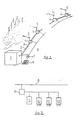
- the snowmaking installation includes a machine room 1 containing the motor-pump and motor-compressor groups which supply water and pressurized air to the lines 2 and 3 arranged along the snow-covered runway. .
- shelters 4 spaced from thirty to fifty meters approximately, which allow on the one hand, to carry out more conveniently the connections of the snow cannons 5 and, on the other hand, to protect and keep out gel, these same connections and the accessories linked to the operation of the guns 5.
- a central computer 6 for managing the snowfall of one or more tracks is connected via an interface 7 and a specialized line 8 of the telephone line type to electronic conversion modules represented in FIG. 2, arranged in the engine room 1 and in each shelter 4.
- the installation also includes temperature and humidity sensors not shown.
- These sensors are arranged at each shelter 4, along the tracks, in the immediate vicinity of the snow cannons 5.
- the signals from these sensors are intended for the computer 6 which manages and controls the snow cover of all tracks.
- the computer will choose the gun (s) that can operate; it will also put into service, in the engine room 14, the motor-pump and motor-compressor groups and control the supply, automatically, of the selected gun (s).
- the electronic conversion module is represented diagrammatically in FIG. 2, it essentially consists of a modem 9 connected to the specialized telephone line 8, an analog-digital converter 10, logic inputs 11 and outputs 12, the whole being managed by a microprocessor 13, the program of which is recorded in a read-only memory of the EPROM type.
- the analog-to-digital converter 10 has several input channels for analog signals coming from pressure, temperature and humidity sensors.
- the logic input 11 is connected to the supply device.
- the signals from the sensors and from the logic input are transmitted to the computer 6 which, in return, and according to its snow program, and via the logic outputs 12 of the corresponding electronic conversion module (s), sets up action on the one hand, the motor-pump and compressor groups in the engine room 1 and on the other hand, the supply device or devices 14, shown in FIG. 3, of the gun (s) 5 chosen.
- shelters there can be a very large number of shelters. With, for example, an eight-bit transmission logic, 255 shelters can be provided, which amounts to covering around ten kilometers. We can also provide, given the length and nesting of the tracks, devices signal regenerators.
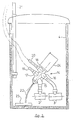
- FIG 3 shows, schematically, a shelter 4 crossed by the pipes 2 and 3 of water and pressurized air.
- This shelter 4 contains a device 14 for feeding a snow cannon; this device 14 is connected by its inlet pipes 15 and 16, to the water 2 and air 3 lines respectively; the outlets 17 and 18 of water and air of the device 14, are connected to the snow cannon by means of flexible pipes 19 and 20.
- the snow cannon is mounted on a pole 21 secured to the shelter.
- the supply device 14 also comprises means making it possible to purge the supply pipe 19 from the barrel 5 and from the barrel itself.
- the pipe 19 of the barrel 5 and the supply device 14 are emptied by gravity; the water flowing through the pipe 22 in the drainage pipe 23 which collects the runoff water at the bottom of each shelter 4.
- the supply device 14 is shown in an inclined position, at an angle of the order 45 °, to allow total drainage by gravity, to avoid any risk of freezing. It is also planned to have around, or in a cavity, inside the body of the supply device 14, a heating means, not shown, of the cane type, which makes it possible to avoid or reduce the risk of freezing. .
- the electronic conversion module in FIG. 2 is preferably housed in a housing 24 arranged in the upper extension of the supply device 14.
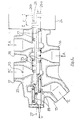
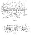
- the supply device 14 is shown in Figure 4; it is in the form of a drawer distributor, comprising a body 25 and a drawer 26 operated by means shown in FIG. 5, which means are arranged in the housing 24.
- the body 25 of the distributor is crossed by the flow of ar (A), the flow of water (E) and the flow of drain water (V).
- the inlets and outlets of the water and air flows are arranged in the same plane passing through the longitudinal axis 27 of the body 25 and of the drawer 26.
- the part of the body 25, through which the air flow passes, is preferably situated on the side of the housing 24 so that, in the event of a leak, between the distributor and the housing, there is no risk of damage to the electrical elements contained in said box 24.
- the various flows are separated by separation zones on the body 25, which zones cooperate with cylindrical valves of the drawer 26.
- the drawer 26 is shown in two halves; half 26a is shown in the active position for closing the water (E) and air (A) flows, and for opening the drain flow (V) half 26b of the drawer 26 is shown in the active position for opening of the water (E) and air (A) flows and closing of the drain flow (V).
- half 26b of the drawer 26 is shown in the active position for opening of the water (E) and air (A) flows and closing of the drain flow (V).
- the total travel C of the slide is broken down. in a series of successive stroke portions which correspond to the implementation of the various functions of the dispenser.
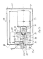
- the displacement of the drawer 26 from position I to position It takes place at very low speed, by means of a control member (FIG. 5), arranged in the housing 24.
- This housing 24 includes a inspection hatch 28 on the top and it is mounted on the body 25, by means of a plate 29, to allow easier assembly and disassembly of said housing 24.
- the actuator of the drawer 26 consists of an electric gear motor 30, with double rotation, which drives a screw 31 of the drawer 26, which drawer has, axially, at its end, a threaded bore 32
- the screw 31 is preferably mounted on a thrust bearing 33, to reduce the operating torque of the drawer 26, and it is secured to the gear motor 30, by a coupling 34.
- the support 35 of the thrust bearing 33 fixed on the body 25 of the dispenser, has a light 36, arranged longitudinally, in which slides a finger 37 partially immobilizing in rotation of the drawer 26.
- the length of the light 36 is greater than the stroke of the drawer 26.
- the finger 37 is disposed perpendicular to the axis 27, in a flange 38, which constitutes the end 39 of the drawer 26.
- the finger 37 extends beyond the light 36 to act on an indicator 40 of position and more particularly of end of travel of drawer 26.
- This indicator 40 is housed in the housing 24, on the front plate 29, integral with the body 25 of the dispenser.
- the end-of-travel indicator 40 of the drawer is connected to the electronic conversion module 41, placed in the housing 24 and is connected to the logic input 11 of the electronic conversion module (FIG. 2).
- This logic input 11 is intended to receive information from two snow-gun supply devices 5.
- the body 25 of the distributor is shown (FIG. 6) without the drawer 26.
- This body 25 comprises, from the end receiving the housing 24, an axial cylindrical zone of separation 42, between the exterior and the air flow (A) and more particularly, the outlet volute 43 of the air flow, which is extended by the outlet pipe 18; the outlet volute 43 and the pipe 18 are aligned along the same median plane 44, perpendicular to the longitudinal axis 27, of the body 25.
- the inlet pipe 16 of the air flow (A) is also extended by a scroll 45, both aligned along a median plane 46, perpendicular to the longitudinal axis 27, of the body 25.
- the two scrolls 43 and 45 are separated by an axial passage 47; the length of the air passage 47 is substantially equal to half the stroke of the drawer.
- This passage 47 comprises, on each side, chamfers 48 and 49, which delimit a cylindrical zone 50, serving as a seat; the length of this zone 50 is substantially equal to half the length of the passage 47.
- An axial cylindrical zone 51 separates the flows of water (E) and air (A) in the body 25; the length of this zone 51 is, in the example described, slightly greater than the travel C of the drawer.
- the water inlet pipe 15 is centered on an axis 57 which makes an angle of about 45 ° with the longitudinal axis 27 of the body 25, to put the distributor in the inclined position, according to FIG. 3.
- the aim of this inclined position is to allow total or almost total emptying of the body 25 of the distributor and, more particularly, from the bottom 58 of the water outlet volute 52.
- the annular part 59 of the water inlet volute is extended by a pavilion 60, up to the cylindrical passage 54. This pavilion 60 is centered on the longitudinal axis 27 and its role will be explained later.
- the section of the pavilion is decreasing, from upstream to downstream, and the profile of said pavilion will be detailed, also below.
- an axial cylindrical zone of separation 61 which isolates said volute 56 and extends to the end of the body 25 of the dispenser.
- the entrance to the cylindrical zone 61 comprises a flange 62 which extends in the annular part 59 of the volute, over a length substantially greater than half of the axial length of said annular part 59.
- the length of the cylindrical zone separation 61 is of the same order as that of separation zone 42, that is to say greater than the travel C of the slide 26.
- the end 63 of the body 25, opposite the end 64 supporting the housing 24, comprises a cap 65, integral with said end 63, by any suitable means.
- This cap 65 is provided with a drain orifice 66 communicating with the outside, by means of the piping 22 (FIG. 3), which pours the flow of drain water V, into the pipe 23.
- the purge orifice 66 is arranged in the lower part of the cap 65.
- the cap 65 also comprises a cylindrical rod 67 centered on the longitudinal axis 27, which extends inside the cylindrical separation zone 61.
- This rod 67 is provided at its end with a shutter 68 and a ring seal 69.
- the diameter of the shutter 68 is of the order of a third of the diameter of the cylindrical separation zone 61.
- the length separating the cap 65 from the seal 69 is substantially greater than the stroke C of the drawer 26. It can be provided to produce the end 63 of the body 25, separately, from the said body, in particular to allow easier machining of the roof 60. In this case, the end 63 would be in the form of a cylindrical sleeve which would include all of the cylindrical separation zone 61.
- the body 25 also comprises, in the outlet pipe 17 of the water flow (E), an orifice 70 intended to receive a pressure sensor which will be connected to the electronic conversion module 41 disposed in the housing 24, and more particularly to the analog to digital converter 10 (FIG. 2) of said electronic conversion module.
- the analog to digital converter 10 can be provided to receive the signals from two pressure sensors corresponding to two supply devices placed close to each other, in the same shelter 4 and which are intended to supply two snow cannons 5.
- the cylindrical separation zones 42, 51, 61 and the cylindrical passages 47, 54 are centered on the longitudinal axis 27 of the body 25 and the diameter of these zones and these passages is preferably identical.
- the slide 26 which moves in the separation zones 42, 51, 61 and the passages 47, 54, is shown in FIG. 7.
- This collar is then extended by a cylindrical rod 71 with a diameter substantially less than the diameter of the separation zone 42 of the body 25 and of a length approximately equal to the stroke C of the drawer.
- a shutter 72 provided with an annular seal 73. This shutter 72 is located in the separation zone 42 of the body 25 and permanently isolates the volute 43 from the flow outlet d outside air, housing side 24.
- the rod 74 connects the shutter 72 to a cylindrical shutter 75 of the same diameter.
- This shutter 75 has two essential functions: it closes the passage 47 of the air flow A, thereby cutting off the air supply to the snow cannon, and it insulates between the air flows A and water E, and more particularly the insulation between the arrival of the air flow A at the volute 45 and the departure of the water flow E, at the volute 52 of the body 25.
- the shutter 75 comprises two annular seals 76 and 77 disposed at each of its ends and a central annular seal 78. The distance separating the two end seals 76 and 77 is substantially equal to the stroke C of the drawer 26.
- the rod 79 is extended by a conical part 80 which connects said rod to a cylindrical shutter 81.
- the half-angle at the top of the conical part is of the order of 45 °.
- the cylindrical shutter 81 performs several functions. First of all, it has two annular seals 82 and 83, one of which, the seal 83 is located at the end 84 of the drawer 26. This annular seal 83 permanently isolates the inlet volute 56 from water from the outside, moving in the cylindrical zone of separation 61 from the body 25.
- the second annular seal 82 is located recessed with respect to the downstream edge 85 of the shutter 81, at the level of the conical part 80; the distance separating the seal 82 from the edge 85 is substantially equal to the radius of the shutter 81.
- the role of the cylindrical zone 86 located between the seal 82 and the edge 85 of the shutter 81 will be explained later.
- the shutter 81 also comprises an axial cylindrical bore 87 which opens, via at least one drilled orifice 88, into the conical connection part 80.
- the two ends 38 and 84 of the drawer 26 communicating with the outside, which makes it possible to balance it and reduce the forces for its movement in the body 25.
- FIG. 8 shows, in detail and in section, the part of the spool valve crossed by the water flow E.
- This part comprises means which make it possible to perform several functions and in particular a shutter function and a function for adjusting the flow rate d 'water.
- the drawer 26 is shown in two halves 26a and 26b; the part 26a of the drawer is in the closed position of the water inlet E; part 26b is in the open position of the water inlet E.
- the flow of water E through the body 25 is stopped by means of the shutter 81 and its two annular seals 82 and 83 which are, respectively, in the active position, on the envelope 55 of the cylindrical passage 54 and on the wall 89 of the cylindrical separation zone 61.
- the water flow through the body 25 is adjusted by rolling the water flow between the edge 85 of the shutter 81 and the roof 60 which extends the annular part 59 of the volute 56 and precedes the passage cylindrical 54.
- the cross-section of the flow of water between the roof 60 and the edge 85 varies as the slide 26 moves, in the body 25, of the dispenser.
- the useful stroke of the drawer for adjusting the water flow rate begins when the edge 85 of the shutter 81 arrives at the fictitious edge 90 separating the roof 60 and the cylindrical passage 54, and it ends when the edge 85 approaches the vertical plane 91 of the entrance to the pavilion 60.
- the seal 82 of said shutter 81 is located clearly upstream in the roof 60, and sufficiently set back so as not to risk being torn off by the water flow.
- the seal 82 is protected by penetrating into the cylindrical separation zone 61 and more particularly into the flange 62 which is arranged in the extension of said separation zone 61.
- the seal 82 will preferably be a seal with high mechanical strength.
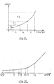
- FIG. 9 illustrates the result obtained when the slide 26 is moved in the body 25 to vary the water flow supplying the snow cannon connected at the outlet of the distributor. Is obtained, through the use of snow cannons according to patent EP-18 280 of the applicant, a proportion of flow rate, substantially constant, regardless of the pressure of the water flow.
- a proportion of flow rate substantially constant, regardless of the pressure of the water flow.
- three types of snow cannons Y1, Y2, Y3 are situated, the flow rates of which can vary from simple to double.
- the small barrel Y1 has a flow rate which can vary from 2.5 to 5 m 3 / h
- the medium barrel Y2 has a flow rate which can vary from 5 to 10 m 3 / h
- the large barrel Y3 has a flow rate which can vary from 10 to 20 m3 / h.
- the pavilion 60 is divided into a certain number of sectors in the form of a truncated cone, between the edge 90 of the body and the plane d entry 91 of said pavilion 60.
- An exemplary embodiment of pavilion 60 is shown in FIG. 10 where, as a function of the distance from the edge 90, expressed in units of length, appears the half-angle at the top of the truncated cones successive.
- the half-angle is 1.8 °; from five to seven units of edge 90, the half angle is 2.6 °; from seven to eight units of the edge, the half angle is 8.8 °; from eleven to fourteen units of the edge, the half-angle is 45 ° and the truncated cone is connected to the annular part 59 of the inlet pipe 56.
- the connection angles, between the truncated cones, are rounded to achieve better continuity of the profile of the roof 60.
- the fourteen length units correspond substantially to the radius of the shutter 81.
- Stroke C of the drawer is broken down into a series of successive stages; at each stage, which corresponds to a very specific portion of the stroke, a particular function of the distributor appears and all of the functions are linked automatically, with great precision and perfect security.
- a first step after a stroke C1 corresponds to the loss of tightness of the flow air; the seal 76 of the shutter 75 has passed from an active sealing position on the envelope 50 of the cylindrical passage 47 to an inactive sealing position at the chamfer 48.
- the next step, after a full stroke C2 corresponds to the closing of the drain, by placing the seal 69 of the rod 67 in the active position, in the cylindrical cavity 87 of the drawer 26.
- the distance which separates, on the body 25, the seal 69, edge 92, chamfer 48, bordering the envelope 50 of passage 47, is greater than the distance which separates, on slide 26, seal 76 from edge 93, at the entrance to the cylindrical cavity 87; this difference provides a delay in closing the purge, relative to the opening of the air flow, and, conversely, it provides an advance at the opening of the purge, relative to the closing of the air flow d air, when the drawer 26 goes from Il to I.
- the seal 82 of the shutter 81, of the slide 26 passes from the active sealing position, downstream of the edge 90, of the body, to the inactive sealing position, upstream of said edge 90
- the distance which separates, on the body 25, the seal 69, from the edge 90 is substantially less, and at the limit equal, to the distance which separates, on the slide 26, the seal 82, of the edge 93, at the entrance to the cylindrical cavity 87.
- the distance separating, on the body 25, the edges 90 and 92 is greater than the distance separating, on the slide 26, the seals 82 and 76.
- the next step corresponds to the passage of a useful flow of water through the body 25; from this stage, and up to the extreme position II of total opening of the water and air flows, the drawer is moved according to the type of snow cannon used, to laminate the flow and not give the cannon only a specific amount of water.
- This quantity of water is determined by the central management computer 6, according to the type of barrel, according to the temperature near the barrel. Obtaining the water flow rate determined by the computer 6 is effected by a displacement of the slide 26 and more particularly of its edge 85, in the pavilion 60. Taking into account that in the water supply to the cannons according to patent EP-18 280, the relationship between the flow and the pressure responds to a well-established law, the control of the flow of water supplying the snow cannon is carried out by means of the pressure sensor positioned in the orifice 70 of the tube 17 for the outlet of the water flow towards the snow cannon.
- the central management computer includes a snowmaking program for the ski slope (s) near which the snow cannons are placed.
- the atmospheric conditions are noted from place to place and more particularly at the level of each shelter 4 where at least one snow cannon is placed.
- the temperature and humidity sensors are connected to the electronic conversion module 41 which is arranged in the housing 24 of the supply device 14 for the snow cannons.
- the information from the temperature and humidity sensors is transformed by the electronic conversion module 41, to be transmitted digitally to the central computer 6, via a simple telephone line 8, to which all the modules are connected.
- Line 8 is connected to the computer by an interface 7 which transforms new digital information 6.
- the electronic conversion module also transmits to the central computer 6, information on the state of the purposes of stroke of the dispenser drawer 26. Each packet of information arrives with the address of the sender and the computer 6 stores this information.
- the central computer 6 When, depending on the planned snow program, the temperature and humidity conditions are reached, the central computer 6 first of all causes the pumps, compressors and their pumps to be started up in the engine room. auxiliaries. This start-up is carried out via the power outputs of an electronic conversion module of the same type as that used by the power supply devices 14, and via the same telephone line 8, which provides one or more machine rooms, as appropriate.
- the electronic engine room conversion module informs the computer 6 of the state of the machines and of the water temperature for example.
- the computer also controls the possible reheating of the bodies 25 of each supply device 14.
- the central computer 6 returns to the ad hoc modules 41, that is to say where the snow conditions are favorable, opening orders of the corresponding drawer dispensers.
- Each electronic conversion module 41 controls, by its power output 12, the gear motor 30 for operating the drawer 26.
- the drawer 26 is moved in the body 25, until a water flow rate is established, in the snow cannon, in relation to the atmospheric conditions of the location of the cannon.
- the control of the flow is carried out by means of a pressure sensor placed in the tube 17 for the outlet of the water flow from the distributor.
- the sensor information is transmitted via the electronic conversion module 41 to the central computer 6 which, in return, gives the orders to maintain the position of the drawer 26 or to change it.
- the computer gives an order which allows, thanks to a preset stroke of the drawer 26, to open the air flow; the water flow is then adjusted, and also according to the evolution of atmospheric conditions.
- the central computer 6 controls the stopping of the snow gun (s), in activity, by giving the electronic conversion modules 41 concerned, the orders closing.
- Each module 41 concerned acts by its logic output 12 of power, on the gear motor 30, to maneuver the slide 26 so as to bring it into the closed position for the flows of water and air and to open the purge, to drain the barrel water circuit.
- the distributor control member can be constituted by a pneumatic or hydraulic system controlled in the same way.
- the dimensions of the body of the dispenser and of the drawer can vary, these dimensions in the example described relate to a concern for minimum bulk, facilitating, moreover, the machining operations.
- the invention can also find other fields of application and more particularly the fields related to the protection of nature and plants, wherever it is advantageous to use an automatic watering or spraying installation.
Landscapes
- Engineering & Computer Science (AREA)
- General Engineering & Computer Science (AREA)
- Mechanical Engineering (AREA)
- Physics & Mathematics (AREA)
- Thermal Sciences (AREA)
- Nozzles (AREA)
- Road Paving Structures (AREA)
- Greenhouses (AREA)
- Buildings Adapted To Withstand Abnormal External Influences (AREA)
- Sowing (AREA)
- Jet Pumps And Other Pumps (AREA)
- Transition And Organic Metals Composition Catalysts For Addition Polymerization (AREA)
- Motor Or Generator Cooling System (AREA)
- Loading And Unloading Of Fuel Tanks Or Ships (AREA)
Priority Applications (1)
| Application Number | Priority Date | Filing Date | Title |
|---|---|---|---|
| AT85402297T ATE41224T1 (de) | 1984-11-27 | 1985-11-25 | Speisevorrichtungen fuer schnee-erzeuger in anlagen fuer kuenstliche schneeversorgung von skipisten. |
Applications Claiming Priority (2)
| Application Number | Priority Date | Filing Date | Title |
|---|---|---|---|
| FR8418236A FR2573854B1 (fr) | 1984-11-27 | 1984-11-27 | Perfectionnement aux dispositifs d'alimentation de canons a neige dans les installations d'enneigement artificiel de pistes de ski |
| FR8418236 | 1984-11-27 |
Publications (2)
| Publication Number | Publication Date |
|---|---|
| EP0187563A1 EP0187563A1 (fr) | 1986-07-16 |
| EP0187563B1 true EP0187563B1 (fr) | 1989-03-08 |
Family
ID=9310087
Family Applications (1)
| Application Number | Title | Priority Date | Filing Date |
|---|---|---|---|
| EP85402297A Expired EP0187563B1 (fr) | 1984-11-27 | 1985-11-25 | Perfectionnement aux dispositifs d'alimentation de canons à neige dans les installations d'enneigement artificiel de pistes de ski |
Country Status (8)
| Country | Link |
|---|---|
| US (1) | US4717072A (cg-RX-API-DMAC7.html) |
| EP (1) | EP0187563B1 (cg-RX-API-DMAC7.html) |
| JP (1) | JPS61197971A (cg-RX-API-DMAC7.html) |
| AT (1) | ATE41224T1 (cg-RX-API-DMAC7.html) |
| CA (1) | CA1298477C (cg-RX-API-DMAC7.html) |
| DE (2) | DE3568629D1 (cg-RX-API-DMAC7.html) |
| ES (1) | ES8708050A1 (cg-RX-API-DMAC7.html) |
| FR (1) | FR2573854B1 (cg-RX-API-DMAC7.html) |
Families Citing this family (24)
| Publication number | Priority date | Publication date | Assignee | Title |
|---|---|---|---|---|
| FR2579732B1 (fr) * | 1985-03-27 | 1987-09-25 | Ene Ste Civile | Dispositifs et procedes de fabrication de neige artificielle |
| FR2623276A1 (fr) * | 1987-11-12 | 1989-05-19 | York Froid Ind | Abri pour installation d'enneigement automatique |
| FR2634663A1 (fr) * | 1988-07-29 | 1990-02-02 | Lagier Jacques | Installation d'enneigement artificiel pour pistes de ski |
| US5031832A (en) * | 1990-01-26 | 1991-07-16 | Ratnik Industries Inc. | Automated snow-making system |
| FR2667681B1 (fr) * | 1990-10-03 | 1993-01-08 | York Froid Ind | Perfectionnement aux abris pour installations d'enneigement automatique. |
| IT1259262B (it) * | 1992-07-31 | 1996-03-11 | Impianto automatico a bassa pressione per la produzione programmata dineve | |
| JPH0682134A (ja) * | 1992-09-03 | 1994-03-22 | Kajima Corp | 人工降雪方法及びその装置 |
| AU730609B2 (en) * | 1992-09-09 | 2001-03-08 | Sims Deltec, Inc. | Systems and methods for communicating with ambulatory medical devices such as drug delivery devices |
| DE4243731C1 (de) * | 1992-12-23 | 1994-05-11 | Manfred Weinrich | Schneekanone |
| US5718378A (en) * | 1995-09-27 | 1998-02-17 | Dupre; Herman K. | Control system for snow making devices |
| US5749517A (en) * | 1995-09-27 | 1998-05-12 | Dupre; Herman K. | Control system for snow making devices |
| US6374848B1 (en) * | 1999-04-15 | 2002-04-23 | Mcghee John D. | Automatic mechanism for cut-off and drainage of under low-freezing ambient temperature conditions |
| FR2795494B1 (fr) | 1999-06-25 | 2001-09-14 | York Neige | Vanne pour la distribution d'eau et eventuellement d'air, dans les installations de pulverisation d'eau sous pression, en vue de la fabrication de neige par exemple |
| US6554200B1 (en) * | 2000-11-01 | 2003-04-29 | Kabushiki Kaisha Piste Snow Industries | System and method for remotely monitoring artificial snow maker of ice crushing type |
| FR2877076A1 (fr) * | 2004-10-27 | 2006-04-28 | Snowstar | Dispositif de production de neige artificielle |
| US7311266B2 (en) * | 2005-01-13 | 2007-12-25 | Santry Charles N | Freeze-proof water valve for supplying secondary water to snow making apparatus |
| FR2914989B1 (fr) * | 2007-04-13 | 2009-07-24 | Johnson Controls Neige Soc Par | Installation d'enneigement et logette pour une telle installation. |
| FR2950124B1 (fr) * | 2009-09-17 | 2011-12-09 | Johnson Controls Neige | Vanne pour la distribution d'eau et d'air dans les installations de pulverisation d'eau sous pression |
| ITVR20120193A1 (it) | 2012-09-28 | 2014-03-29 | Technoalpin A G S P A | Sistema di controllo per un impianto di innevamento artificiale |
| PL3268683T3 (pl) | 2015-03-13 | 2024-12-16 | Sl Usa, Llc | Podwójny automatyczny hydrant do armatki śnieżnej oraz sposób jego użycia |
| CA2981878C (en) | 2015-04-06 | 2023-11-14 | Snow Logic, Inc. | Snowmaking automation system and modules |
| ES2953630T3 (es) | 2017-09-14 | 2023-11-14 | Agility Fuel Systems Llc | Sistemas para monitorización de componentes de sistemas de combustible volátil |
| US10942533B2 (en) * | 2018-02-14 | 2021-03-09 | Hexagon Technology As | System for multiple pressure relief device activation |
| EP4378735A3 (en) | 2019-11-25 | 2024-08-07 | Agility Fuel Systems LLC | Improved pressure relief device |
Family Cites Families (21)
| Publication number | Priority date | Publication date | Assignee | Title |
|---|---|---|---|---|
| US584682A (en) * | 1897-06-15 | Water-plug | ||
| US979941A (en) * | 1910-08-19 | 1910-12-27 | John Lansing Fuller | Hydrant and valve therefor. |
| US1276677A (en) * | 1917-06-13 | 1918-08-20 | Saul Mittleburg | Bracket. |
| US2011329A (en) * | 1935-02-19 | 1935-08-13 | Wayer Henry | Faucet |
| FR966043A (fr) * | 1948-05-05 | 1950-09-28 | Distribution à tiroir destiné à commander automatiquement les circuits chauffantset réfrigérants des générateurs utilisant comme véhicules de chaleur des liquides spéciaux | |
| US3080952A (en) * | 1958-11-25 | 1963-03-12 | Carlstedt Sven Borje Fredrik | Valve device operated by reversible electric motor |
| US3372872A (en) * | 1966-07-26 | 1968-03-12 | George F. Le Bus | Artificial snow production |
| US3706414A (en) * | 1970-10-07 | 1972-12-19 | Herman K Dupre | Apparatus for making snow |
| US3761020A (en) * | 1972-02-17 | 1973-09-25 | J Tropeano | Method and apparatus for snow making |
| US3756282A (en) * | 1972-05-30 | 1973-09-04 | Applied Power Inc | Electric motor controlled fluid valve |
| US3841555A (en) * | 1972-08-14 | 1974-10-15 | D Lilja | Spray apparatus and method |
| JPS49142856U (cg-RX-API-DMAC7.html) * | 1973-04-04 | 1974-12-10 | ||
| DE2551180A1 (de) * | 1975-11-14 | 1977-05-26 | Hankinson Corp | Vielzweckventil |
| US4128203A (en) * | 1977-09-01 | 1978-12-05 | Eaton Corporation | Four-port thermally responsive valve |
| FR2421353A1 (fr) * | 1978-03-31 | 1979-10-26 | Armand Daniel | Procede et dispositif de fabrication automatique de neige |
| US4228817A (en) * | 1978-06-01 | 1980-10-21 | Robertshaw Controls Company | Valve construction having multiple piston means |
| US4210169A (en) * | 1978-08-18 | 1980-07-01 | Palma Florencio N | Sprinkler control valve |
| FR2454593A1 (fr) * | 1979-04-20 | 1980-11-14 | York Sa Froid Indl | Appareil haute pression de production de neige artificielle avec reglage du melange air/eau en fonction de la temperature humide de l'air ambiant |
| US4545529A (en) * | 1982-08-12 | 1985-10-08 | Tropeano Joseph C | Method and apparatus for automatically making snow |
| US4511083A (en) * | 1983-05-16 | 1985-04-16 | Ratnik Industries, Inc. | Self-regulating hydrant |
| US4503888A (en) * | 1983-10-04 | 1985-03-12 | Mts Systems Corporation | Servovalve spool control for digital rotary servovalve |
-
1984
- 1984-11-27 FR FR8418236A patent/FR2573854B1/fr not_active Expired
-
1985
- 1985-11-19 CA CA000495617A patent/CA1298477C/fr not_active Expired - Lifetime
- 1985-11-25 EP EP85402297A patent/EP0187563B1/fr not_active Expired
- 1985-11-25 DE DE8585402297T patent/DE3568629D1/de not_active Expired
- 1985-11-25 DE DE198585402297T patent/DE187563T1/de active Pending
- 1985-11-25 AT AT85402297T patent/ATE41224T1/de not_active IP Right Cessation
- 1985-11-26 JP JP60263962A patent/JPS61197971A/ja active Granted
- 1985-11-26 US US06/802,043 patent/US4717072A/en not_active Expired - Lifetime
- 1985-11-26 ES ES549278A patent/ES8708050A1/es not_active Expired
Also Published As
| Publication number | Publication date |
|---|---|
| DE3568629D1 (en) | 1989-04-13 |
| FR2573854B1 (fr) | 1987-04-24 |
| ES549278A0 (es) | 1987-09-01 |
| EP0187563A1 (fr) | 1986-07-16 |
| FR2573854A1 (fr) | 1986-05-30 |
| ES8708050A1 (es) | 1987-09-01 |
| JPH0517468B2 (cg-RX-API-DMAC7.html) | 1993-03-09 |
| JPS61197971A (ja) | 1986-09-02 |
| ATE41224T1 (de) | 1989-03-15 |
| DE187563T1 (de) | 1987-05-21 |
| CA1298477C (fr) | 1992-04-07 |
| US4717072A (en) | 1988-01-05 |
Similar Documents
| Publication | Publication Date | Title |
|---|---|---|
| EP0187563B1 (fr) | Perfectionnement aux dispositifs d'alimentation de canons à neige dans les installations d'enneigement artificiel de pistes de ski | |
| EP2478277B1 (fr) | Vanne pour la distribution d'eau et d'air dans les installations de pulverisation d'eau sous pression | |
| EP0201398B1 (fr) | Ensemble permettant d'effectuer des forages orientés | |
| EP0520852B1 (fr) | Vanne raclable à trois voies, du type à papillon | |
| FR2862723A1 (fr) | Turbine et centrale hydraulique pour tres basse chute | |
| FR2998867A1 (fr) | Dispositif d'alimentation et de repartition de fluide | |
| EP2444748B1 (fr) | Installation de production d'eau chaude sanitaire pour habitation collective comprenant un ventilateur d'extraction d'air commun | |
| FR2504844A1 (fr) | Systeme de maconnage pour boulon de voute, notamment de galerie de mine | |
| WO1994023254A1 (fr) | Buse de pulverisation et dispositif de pulverisation d'un melange d'eau et d'air utilisant ladite buse | |
| EP3177571B1 (fr) | Dispositif de traitement d'eau de grande capacité | |
| EP3190346B1 (fr) | Dispositif de connexion relais pour installation de ventilation forcee, systeme de connexion relais le comprenant, et installation de ventilation forcee equipee de tels systemes | |
| WO1988003246A1 (fr) | Installation d'enfutage | |
| WO2018060755A1 (fr) | Installation de traitement de fluides par osmose inverse | |
| EP3043920B1 (fr) | Système de pulvérisation pour enneigeur à alimentation bi-fluide | |
| WO1994020222A1 (fr) | Support pour un dispositif de pulverisation d'un melange d'eau et d'air sous pression | |
| EP4172488B1 (fr) | Installation hydraulique pour réseau d'eau et réseau d'eau comportant une telle installation | |
| EP3689435A1 (fr) | Filtre pour produit liquide ou visqueux et installation de pulvérisation comprenant un tel filtre | |
| EP3164548B1 (fr) | Dispositif de distribution d'eau anti-gel | |
| FR2517774A1 (fr) | Ensemble d'entrainement a vitesse variable | |
| CH364694A (fr) | Pompe à vanne incorporée, pour installations de chauffage central | |
| FR2537018A1 (fr) | Distributeur pour une installation mobile de pulverisation d'un liquide de traitement des plantes | |
| WO2011083164A1 (fr) | Dispositif anti-gel de distribution d'eau | |
| FR2619196A1 (fr) | Dispositif de sectionnement automatique pour reseau de transport de fluide sous double enveloppe | |
| FR2512163A1 (fr) | Bouche de distribution de fluide a debit independant de la pression | |
| FR3015621A1 (fr) | Vanne de commande avec segment d'etancheite en escalier |
Legal Events
| Date | Code | Title | Description |
|---|---|---|---|
| PUAI | Public reference made under article 153(3) epc to a published international application that has entered the european phase |
Free format text: ORIGINAL CODE: 0009012 |
|
| AK | Designated contracting states |
Kind code of ref document: A1 Designated state(s): AT CH DE IT LI SE |
|
| ITCL | It: translation for ep claims filed |
Representative=s name: STUDIO TORTA SOCIETA' SEMPLICE |
|
| 17P | Request for examination filed |
Effective date: 19860924 |
|
| TCAT | At: translation of patent claims filed | ||
| DET | De: translation of patent claims | ||
| 17Q | First examination report despatched |
Effective date: 19870605 |
|
| GRAA | (expected) grant |
Free format text: ORIGINAL CODE: 0009210 |
|
| AK | Designated contracting states |
Kind code of ref document: B1 Designated state(s): AT CH DE IT LI SE |
|
| REF | Corresponds to: |
Ref document number: 41224 Country of ref document: AT Date of ref document: 19890315 Kind code of ref document: T |
|
| REF | Corresponds to: |
Ref document number: 3568629 Country of ref document: DE Date of ref document: 19890413 |
|
| ITF | It: translation for a ep patent filed | ||
| PLBE | No opposition filed within time limit |
Free format text: ORIGINAL CODE: 0009261 |
|
| STAA | Information on the status of an ep patent application or granted ep patent |
Free format text: STATUS: NO OPPOSITION FILED WITHIN TIME LIMIT |
|
| 26N | No opposition filed | ||
| ITTA | It: last paid annual fee | ||
| EAL | Se: european patent in force in sweden |
Ref document number: 85402297.7 |
|
| REG | Reference to a national code |
Ref country code: CH Ref legal event code: PUE Owner name: YORK FRANCE AIRCHAL Ref country code: CH Ref legal event code: PFA Free format text: YORK FRANCE S.A. |
|
| ITPR | It: changes in ownership of a european patent |
Owner name: CESSIONE;YORK FRANCE AIRCHAL S.A. |
|
| PGFP | Annual fee paid to national office [announced via postgrant information from national office to epo] |
Ref country code: SE Payment date: 20021119 Year of fee payment: 18 |
|
| PGFP | Annual fee paid to national office [announced via postgrant information from national office to epo] |
Ref country code: DE Payment date: 20030110 Year of fee payment: 18 |
|
| PGFP | Annual fee paid to national office [announced via postgrant information from national office to epo] |
Ref country code: CH Payment date: 20030206 Year of fee payment: 18 |
|
| PG25 | Lapsed in a contracting state [announced via postgrant information from national office to epo] |
Ref country code: SE Free format text: LAPSE BECAUSE OF NON-PAYMENT OF DUE FEES Effective date: 20031126 |
|
| PG25 | Lapsed in a contracting state [announced via postgrant information from national office to epo] |
Ref country code: LI Free format text: LAPSE BECAUSE OF NON-PAYMENT OF DUE FEES Effective date: 20031130 Ref country code: CH Free format text: LAPSE BECAUSE OF NON-PAYMENT OF DUE FEES Effective date: 20031130 |
|
| PG25 | Lapsed in a contracting state [announced via postgrant information from national office to epo] |
Ref country code: DE Free format text: LAPSE BECAUSE OF NON-PAYMENT OF DUE FEES Effective date: 20040602 |
|
| EUG | Se: european patent has lapsed | ||
| REG | Reference to a national code |
Ref country code: CH Ref legal event code: PL |
|
| PGFP | Annual fee paid to national office [announced via postgrant information from national office to epo] |
Ref country code: AT Payment date: 20041116 Year of fee payment: 20 |