EP0187563B1 - Snow gun feeding devices in systems for providing ski slopes with artificial snow - Google Patents
Snow gun feeding devices in systems for providing ski slopes with artificial snow Download PDFInfo
- Publication number
- EP0187563B1 EP0187563B1 EP85402297A EP85402297A EP0187563B1 EP 0187563 B1 EP0187563 B1 EP 0187563B1 EP 85402297 A EP85402297 A EP 85402297A EP 85402297 A EP85402297 A EP 85402297A EP 0187563 B1 EP0187563 B1 EP 0187563B1
- Authority
- EP
- European Patent Office
- Prior art keywords
- water
- snow
- feeding device
- slide valve
- distributor
- Prior art date
- Legal status (The legal status is an assumption and is not a legal conclusion. Google has not performed a legal analysis and makes no representation as to the accuracy of the status listed.)
- Expired
Links
Images

Classifications
-
- F—MECHANICAL ENGINEERING; LIGHTING; HEATING; WEAPONS; BLASTING
- F25—REFRIGERATION OR COOLING; COMBINED HEATING AND REFRIGERATION SYSTEMS; HEAT PUMP SYSTEMS; MANUFACTURE OR STORAGE OF ICE; LIQUEFACTION SOLIDIFICATION OF GASES
- F25C—PRODUCING, WORKING OR HANDLING ICE
- F25C3/00—Processes or apparatus specially adapted for producing ice or snow for winter sports or similar recreational purposes, e.g. for sporting installations; Producing artificial snow
- F25C3/04—Processes or apparatus specially adapted for producing ice or snow for winter sports or similar recreational purposes, e.g. for sporting installations; Producing artificial snow for sledging or ski trails; Producing artificial snow
-
- F—MECHANICAL ENGINEERING; LIGHTING; HEATING; WEAPONS; BLASTING
- F16—ENGINEERING ELEMENTS AND UNITS; GENERAL MEASURES FOR PRODUCING AND MAINTAINING EFFECTIVE FUNCTIONING OF MACHINES OR INSTALLATIONS; THERMAL INSULATION IN GENERAL
- F16K—VALVES; TAPS; COCKS; ACTUATING-FLOATS; DEVICES FOR VENTING OR AERATING
- F16K11/00—Multiple-way valves, e.g. mixing valves; Pipe fittings incorporating such valves
- F16K11/02—Multiple-way valves, e.g. mixing valves; Pipe fittings incorporating such valves with all movable sealing faces moving as one unit
- F16K11/06—Multiple-way valves, e.g. mixing valves; Pipe fittings incorporating such valves with all movable sealing faces moving as one unit comprising only sliding valves, i.e. sliding closure elements
- F16K11/065—Multiple-way valves, e.g. mixing valves; Pipe fittings incorporating such valves with all movable sealing faces moving as one unit comprising only sliding valves, i.e. sliding closure elements with linearly sliding closure members
- F16K11/07—Multiple-way valves, e.g. mixing valves; Pipe fittings incorporating such valves with all movable sealing faces moving as one unit comprising only sliding valves, i.e. sliding closure elements with linearly sliding closure members with cylindrical slides
- F16K11/0716—Multiple-way valves, e.g. mixing valves; Pipe fittings incorporating such valves with all movable sealing faces moving as one unit comprising only sliding valves, i.e. sliding closure elements with linearly sliding closure members with cylindrical slides with fluid passages through the valve member
-
- F—MECHANICAL ENGINEERING; LIGHTING; HEATING; WEAPONS; BLASTING
- F25—REFRIGERATION OR COOLING; COMBINED HEATING AND REFRIGERATION SYSTEMS; HEAT PUMP SYSTEMS; MANUFACTURE OR STORAGE OF ICE; LIQUEFACTION SOLIDIFICATION OF GASES
- F25C—PRODUCING, WORKING OR HANDLING ICE
- F25C2303/00—Special arrangements or features for producing ice or snow for winter sports or similar recreational purposes, e.g. for sporting installations; Special arrangements or features for producing artificial snow
- F25C2303/048—Snow making by using means for spraying water
- F25C2303/0481—Snow making by using means for spraying water with the use of compressed air
-
- Y—GENERAL TAGGING OF NEW TECHNOLOGICAL DEVELOPMENTS; GENERAL TAGGING OF CROSS-SECTIONAL TECHNOLOGIES SPANNING OVER SEVERAL SECTIONS OF THE IPC; TECHNICAL SUBJECTS COVERED BY FORMER USPC CROSS-REFERENCE ART COLLECTIONS [XRACs] AND DIGESTS
- Y10—TECHNICAL SUBJECTS COVERED BY FORMER USPC
- Y10T—TECHNICAL SUBJECTS COVERED BY FORMER US CLASSIFICATION
- Y10T137/00—Fluid handling
- Y10T137/1189—Freeze condition responsive safety systems
- Y10T137/1353—Low temperature responsive drains
-
- Y—GENERAL TAGGING OF NEW TECHNOLOGICAL DEVELOPMENTS; GENERAL TAGGING OF CROSS-SECTIONAL TECHNOLOGIES SPANNING OVER SEVERAL SECTIONS OF THE IPC; TECHNICAL SUBJECTS COVERED BY FORMER USPC CROSS-REFERENCE ART COLLECTIONS [XRACs] AND DIGESTS
- Y10—TECHNICAL SUBJECTS COVERED BY FORMER USPC
- Y10T—TECHNICAL SUBJECTS COVERED BY FORMER US CLASSIFICATION
- Y10T137/00—Fluid handling
- Y10T137/1842—Ambient condition change responsive
- Y10T137/1939—Atmospheric
- Y10T137/1963—Temperature
Definitions
- the present invention relates to an improvement to the devices for feeding snow cannons in the artificial snowmaking installations of ski slopes, as described for example in patents US-A-3,706,414, 3,372,872, or else 2. 676,471.
- the artificial snowmaking of ski slopes is achieved in a known manner by spraying on the intended location, a mixture of air and water in the form of a mist, in the ambient air at low temperature at by means of a snow cannon and, for the present installation according to the invention, by means of snow cannons as described in patent EP-18,280 of the applicant.
- the choice of tracks and the start-up of the installation are decided by a central computer which takes into account the temperature, from place to place, along the track.
- the only prior manual operation results from the choice of cannons which will be used to reload this or that sector of the particularly eroded runway, for example; this manual operation consists in opening the air and water valves in each selected shelter, before authorizing the commissioning of the installation.
- the present invention aims to remedy the drawbacks of current installations.
- a first object of the invention is to obtain an automatic device combining high precision and perfect security in the sequence of openings and closings of the water and air flows.
- This automation also makes it possible to eliminate the manual intervention of operators in the shelters arranged along the track putting the installation on standby; these manual interventions being them most often painful, because of the climatic conditions, and very expensive.
- Another object of the invention is to provide an installation the snow production capacities of which are greatly increased by virtue of the possibility of having and controlling a very large number of guns on the edge of the tracks.
- Another important object of the invention is to achieve the realization of an installation which does not constitute a prohibitive investment, given the very large number of guns that it is possible to use.
- the invention proposes a new device for feeding snow cannons; this device is located in each shelter, along the runway, and it consists of a multi-function drawer distributor connected to the water and pressurized air lines to supply a snow cannon.
- Drawer distributors are known members, usable in various applications and in very varied forms.
- the document FR-A-966 043 for example, relates to a particular application of a drawer distributor for the automatic control of heat generators.
- Patent DE-A-2,551,180 shows a dispenser made up of modular elements.
- the feeding device for snow cannon is located in shelters or ski slopes and these shelters are crossed by water and pressurized air pipes.
- the drawer dispenser comprises an elongated body, provided with: water and air inlet pipes connected to the water and air pipes, water and air outlet pipes connected by pipes to the snow cannon, and a purge orifice.
- the dispenser also includes a cylindrical drawer provided with cylindrical shutters and driven by a control member, so as to slide in the body between a closed position for the flow of water and air in which the water outlet pipe is in communication with the purge orifice, to ensure emptying, and a position for opening the water and air flows and for closing the emptying.
- the supply device comprises means for automatic control of the dispenser drawer consisting of a member for operating the drawer and a system for controlling the operating member.
- the air flow passes through the body of the distributor, in its extreme part, located on the side of the operating member of the drawer, and the bleed orifice is located at the other end of the body.
- the distributor body has cylindrical sections for the passage of water and air flows, cooperating with cylindrical shutters on the slide and, according to an arrangement of the invention, the distance separating the upstream edges of the cylindrical sections for passage of the flow of water and air in the body, is greater than the distance separating the seals, in relation, from the shutters of water and air under pressure, from the drawer, to achieve a delay of the opening of water relative to the air opening.
- the water shutter comprises, downstream of the seal, a cylindrical portion achieving a significant pressure drop and the length of which is substantially equal to one-third of the drawer stroke, for gradually establish the flow of water through the distributor.
- the purging is carried out by means of placing the distributor's water outlet tubing in communication with the outside, through a cylindrical cavity of the drawer and through orifices, drilled through the drawer, and opening into the volute of the outlet pipe, which cylindrical cavity is closed by a cylindrical rod secured to the body; the distance separating the seal from the cylindrical rod, from the upstream edge of the air flow passage section, is greater than the distance separating the inlet edge from the cylindrical cavity of the drawer, from the seal of the air flow shutter and, the distance separating the seal from the cylindrical rod, is less than the distance separating the entry edge from the cylindrical cavity of the drawer, of the seal sealing of the shutter of the passage of the water flow, to achieve a delay in the closing of the purge relative to the opening of the air, this delay being however less than the delay in opening the water by compared to the same air opening.
- the distributor performs an additional function of automatic adjustment of the water flow intended for the barrel.
- the means for adjusting the water flow essentially consist, in the body of the distributor, in a part with variable section, in the shape of a flag, increasing from downstream to upstream which, in cooperation with the downstream edge of the shutter for the passage of the water flow, laminates the said flow of water, before the cylindrical passage which is bordered by upstream and downstream edges.
- the flow rate of the water flow passing through the dispenser is adjusted by controlled movement of the slide in the body of the dispenser and the passage section of the water stream is such that, for the same movement of the slide, the percentage increase in flow is constant, regardless of the pressure of the feed water.
- the feed device for the snow cannon comprises a member for operating the distributor drawer.
- This operating member consists of an electric geared motor with two directions of rotation.
- This gear motor acts on the drawer, by means of a screw engaging in a threaded bore at the end of the drawer.
- the drawer operating screw comprises a thrust bearing making it possible to reduce the operating torque of the drawer.
- the drawer is immobilized, partially in rotation, by means of a finger guided in a longitudinal slot, which finger cooperates with a device indicating the position of the drawer.
- the operating member of the drawer is arranged in a housing integral with the end of the body of the dispenser.
- the electric geared motor is controlled, according to the invention, by means of a servo system consisting of a central computer for managing the snow cover of the tracks connected by a line of the telephone line type, to electronic modules of conversion arranged in the casings of the cannon feeding devices.
- these electronic conversion modules essentially comprise a modem, an analog-to-digital converter, logic inputs and outputs, all managed by a microprocessor comprising a read-only memory of the EPROM type.
- the logic power outputs are connected to the operating element of the distributor drawer the logic inputs are connected to the indicator position and limit switch located in the housing: the analog inputs receive the signals from the pressure sensor placed in the distributor's water outlet pipe, and temperature and humidity sensors arranged near the snow cannon.
- the subject of the invention is also, the installation which comprises, on the one hand, such a snow-gun feeding device and, on the other hand, the assembly allowing the remote control of said feeding device constituted in particular by the electronic conversion modules each connected to a single telephone line, yes is connected to a computer, via an interface.
- the invention enables snow cannons to be fed, without having to move one or more operators, to each of the shelters;
- the central management computer takes into account all the parameters related to the operation of the snow gun (s) and, according to these parameters, makes a choice among the guns and puts into service the motor-pump and motor-compressor groups.
- the computer also makes it possible to modify, depending on the temperature, the water flow rate of each cannon and, depending on the number of snow cannons to be used, to modify the choice of cannons to adapt this choice to the possibilities of the motorcycle group -pumps and motor-compressors.
- the snowmaking installation includes a machine room 1 containing the motor-pump and motor-compressor groups which supply water and pressurized air to the lines 2 and 3 arranged along the snow-covered runway. .
- shelters 4 spaced from thirty to fifty meters approximately, which allow on the one hand, to carry out more conveniently the connections of the snow cannons 5 and, on the other hand, to protect and keep out gel, these same connections and the accessories linked to the operation of the guns 5.
- a central computer 6 for managing the snowfall of one or more tracks is connected via an interface 7 and a specialized line 8 of the telephone line type to electronic conversion modules represented in FIG. 2, arranged in the engine room 1 and in each shelter 4.
- the installation also includes temperature and humidity sensors not shown.
- These sensors are arranged at each shelter 4, along the tracks, in the immediate vicinity of the snow cannons 5.
- the signals from these sensors are intended for the computer 6 which manages and controls the snow cover of all tracks.
- the computer will choose the gun (s) that can operate; it will also put into service, in the engine room 14, the motor-pump and motor-compressor groups and control the supply, automatically, of the selected gun (s).
- the electronic conversion module is represented diagrammatically in FIG. 2, it essentially consists of a modem 9 connected to the specialized telephone line 8, an analog-digital converter 10, logic inputs 11 and outputs 12, the whole being managed by a microprocessor 13, the program of which is recorded in a read-only memory of the EPROM type.
- the analog-to-digital converter 10 has several input channels for analog signals coming from pressure, temperature and humidity sensors.
- the logic input 11 is connected to the supply device.
- the signals from the sensors and from the logic input are transmitted to the computer 6 which, in return, and according to its snow program, and via the logic outputs 12 of the corresponding electronic conversion module (s), sets up action on the one hand, the motor-pump and compressor groups in the engine room 1 and on the other hand, the supply device or devices 14, shown in FIG. 3, of the gun (s) 5 chosen.
- shelters there can be a very large number of shelters. With, for example, an eight-bit transmission logic, 255 shelters can be provided, which amounts to covering around ten kilometers. We can also provide, given the length and nesting of the tracks, devices signal regenerators.
- FIG 3 shows, schematically, a shelter 4 crossed by the pipes 2 and 3 of water and pressurized air.
- This shelter 4 contains a device 14 for feeding a snow cannon; this device 14 is connected by its inlet pipes 15 and 16, to the water 2 and air 3 lines respectively; the outlets 17 and 18 of water and air of the device 14, are connected to the snow cannon by means of flexible pipes 19 and 20.
- the snow cannon is mounted on a pole 21 secured to the shelter.
- the supply device 14 also comprises means making it possible to purge the supply pipe 19 from the barrel 5 and from the barrel itself.
- the pipe 19 of the barrel 5 and the supply device 14 are emptied by gravity; the water flowing through the pipe 22 in the drainage pipe 23 which collects the runoff water at the bottom of each shelter 4.
- the supply device 14 is shown in an inclined position, at an angle of the order 45 °, to allow total drainage by gravity, to avoid any risk of freezing. It is also planned to have around, or in a cavity, inside the body of the supply device 14, a heating means, not shown, of the cane type, which makes it possible to avoid or reduce the risk of freezing. .
- the electronic conversion module in FIG. 2 is preferably housed in a housing 24 arranged in the upper extension of the supply device 14.
- the supply device 14 is shown in Figure 4; it is in the form of a drawer distributor, comprising a body 25 and a drawer 26 operated by means shown in FIG. 5, which means are arranged in the housing 24.
- the body 25 of the distributor is crossed by the flow of ar (A), the flow of water (E) and the flow of drain water (V).
- the inlets and outlets of the water and air flows are arranged in the same plane passing through the longitudinal axis 27 of the body 25 and of the drawer 26.
- the part of the body 25, through which the air flow passes, is preferably situated on the side of the housing 24 so that, in the event of a leak, between the distributor and the housing, there is no risk of damage to the electrical elements contained in said box 24.
- the various flows are separated by separation zones on the body 25, which zones cooperate with cylindrical valves of the drawer 26.
- the drawer 26 is shown in two halves; half 26a is shown in the active position for closing the water (E) and air (A) flows, and for opening the drain flow (V) half 26b of the drawer 26 is shown in the active position for opening of the water (E) and air (A) flows and closing of the drain flow (V).
- half 26b of the drawer 26 is shown in the active position for opening of the water (E) and air (A) flows and closing of the drain flow (V).
- the total travel C of the slide is broken down. in a series of successive stroke portions which correspond to the implementation of the various functions of the dispenser.
- the displacement of the drawer 26 from position I to position It takes place at very low speed, by means of a control member (FIG. 5), arranged in the housing 24.
- This housing 24 includes a inspection hatch 28 on the top and it is mounted on the body 25, by means of a plate 29, to allow easier assembly and disassembly of said housing 24.
- the actuator of the drawer 26 consists of an electric gear motor 30, with double rotation, which drives a screw 31 of the drawer 26, which drawer has, axially, at its end, a threaded bore 32
- the screw 31 is preferably mounted on a thrust bearing 33, to reduce the operating torque of the drawer 26, and it is secured to the gear motor 30, by a coupling 34.
- the support 35 of the thrust bearing 33 fixed on the body 25 of the dispenser, has a light 36, arranged longitudinally, in which slides a finger 37 partially immobilizing in rotation of the drawer 26.
- the length of the light 36 is greater than the stroke of the drawer 26.
- the finger 37 is disposed perpendicular to the axis 27, in a flange 38, which constitutes the end 39 of the drawer 26.
- the finger 37 extends beyond the light 36 to act on an indicator 40 of position and more particularly of end of travel of drawer 26.
- This indicator 40 is housed in the housing 24, on the front plate 29, integral with the body 25 of the dispenser.
- the end-of-travel indicator 40 of the drawer is connected to the electronic conversion module 41, placed in the housing 24 and is connected to the logic input 11 of the electronic conversion module (FIG. 2).
- This logic input 11 is intended to receive information from two snow-gun supply devices 5.
- the body 25 of the distributor is shown (FIG. 6) without the drawer 26.
- This body 25 comprises, from the end receiving the housing 24, an axial cylindrical zone of separation 42, between the exterior and the air flow (A) and more particularly, the outlet volute 43 of the air flow, which is extended by the outlet pipe 18; the outlet volute 43 and the pipe 18 are aligned along the same median plane 44, perpendicular to the longitudinal axis 27, of the body 25.
- the inlet pipe 16 of the air flow (A) is also extended by a scroll 45, both aligned along a median plane 46, perpendicular to the longitudinal axis 27, of the body 25.
- the two scrolls 43 and 45 are separated by an axial passage 47; the length of the air passage 47 is substantially equal to half the stroke of the drawer.
- This passage 47 comprises, on each side, chamfers 48 and 49, which delimit a cylindrical zone 50, serving as a seat; the length of this zone 50 is substantially equal to half the length of the passage 47.
- An axial cylindrical zone 51 separates the flows of water (E) and air (A) in the body 25; the length of this zone 51 is, in the example described, slightly greater than the travel C of the drawer.
- the water inlet pipe 15 is centered on an axis 57 which makes an angle of about 45 ° with the longitudinal axis 27 of the body 25, to put the distributor in the inclined position, according to FIG. 3.
- the aim of this inclined position is to allow total or almost total emptying of the body 25 of the distributor and, more particularly, from the bottom 58 of the water outlet volute 52.
- the annular part 59 of the water inlet volute is extended by a pavilion 60, up to the cylindrical passage 54. This pavilion 60 is centered on the longitudinal axis 27 and its role will be explained later.
- the section of the pavilion is decreasing, from upstream to downstream, and the profile of said pavilion will be detailed, also below.
- an axial cylindrical zone of separation 61 which isolates said volute 56 and extends to the end of the body 25 of the dispenser.
- the entrance to the cylindrical zone 61 comprises a flange 62 which extends in the annular part 59 of the volute, over a length substantially greater than half of the axial length of said annular part 59.
- the length of the cylindrical zone separation 61 is of the same order as that of separation zone 42, that is to say greater than the travel C of the slide 26.
- the end 63 of the body 25, opposite the end 64 supporting the housing 24, comprises a cap 65, integral with said end 63, by any suitable means.
- This cap 65 is provided with a drain orifice 66 communicating with the outside, by means of the piping 22 (FIG. 3), which pours the flow of drain water V, into the pipe 23.
- the purge orifice 66 is arranged in the lower part of the cap 65.
- the cap 65 also comprises a cylindrical rod 67 centered on the longitudinal axis 27, which extends inside the cylindrical separation zone 61.
- This rod 67 is provided at its end with a shutter 68 and a ring seal 69.
- the diameter of the shutter 68 is of the order of a third of the diameter of the cylindrical separation zone 61.
- the length separating the cap 65 from the seal 69 is substantially greater than the stroke C of the drawer 26. It can be provided to produce the end 63 of the body 25, separately, from the said body, in particular to allow easier machining of the roof 60. In this case, the end 63 would be in the form of a cylindrical sleeve which would include all of the cylindrical separation zone 61.
- the body 25 also comprises, in the outlet pipe 17 of the water flow (E), an orifice 70 intended to receive a pressure sensor which will be connected to the electronic conversion module 41 disposed in the housing 24, and more particularly to the analog to digital converter 10 (FIG. 2) of said electronic conversion module.
- the analog to digital converter 10 can be provided to receive the signals from two pressure sensors corresponding to two supply devices placed close to each other, in the same shelter 4 and which are intended to supply two snow cannons 5.
- the cylindrical separation zones 42, 51, 61 and the cylindrical passages 47, 54 are centered on the longitudinal axis 27 of the body 25 and the diameter of these zones and these passages is preferably identical.
- the slide 26 which moves in the separation zones 42, 51, 61 and the passages 47, 54, is shown in FIG. 7.
- This collar is then extended by a cylindrical rod 71 with a diameter substantially less than the diameter of the separation zone 42 of the body 25 and of a length approximately equal to the stroke C of the drawer.
- a shutter 72 provided with an annular seal 73. This shutter 72 is located in the separation zone 42 of the body 25 and permanently isolates the volute 43 from the flow outlet d outside air, housing side 24.
- the rod 74 connects the shutter 72 to a cylindrical shutter 75 of the same diameter.
- This shutter 75 has two essential functions: it closes the passage 47 of the air flow A, thereby cutting off the air supply to the snow cannon, and it insulates between the air flows A and water E, and more particularly the insulation between the arrival of the air flow A at the volute 45 and the departure of the water flow E, at the volute 52 of the body 25.
- the shutter 75 comprises two annular seals 76 and 77 disposed at each of its ends and a central annular seal 78. The distance separating the two end seals 76 and 77 is substantially equal to the stroke C of the drawer 26.
- the rod 79 is extended by a conical part 80 which connects said rod to a cylindrical shutter 81.
- the half-angle at the top of the conical part is of the order of 45 °.
- the cylindrical shutter 81 performs several functions. First of all, it has two annular seals 82 and 83, one of which, the seal 83 is located at the end 84 of the drawer 26. This annular seal 83 permanently isolates the inlet volute 56 from water from the outside, moving in the cylindrical zone of separation 61 from the body 25.
- the second annular seal 82 is located recessed with respect to the downstream edge 85 of the shutter 81, at the level of the conical part 80; the distance separating the seal 82 from the edge 85 is substantially equal to the radius of the shutter 81.
- the role of the cylindrical zone 86 located between the seal 82 and the edge 85 of the shutter 81 will be explained later.
- the shutter 81 also comprises an axial cylindrical bore 87 which opens, via at least one drilled orifice 88, into the conical connection part 80.
- the two ends 38 and 84 of the drawer 26 communicating with the outside, which makes it possible to balance it and reduce the forces for its movement in the body 25.
- FIG. 8 shows, in detail and in section, the part of the spool valve crossed by the water flow E.
- This part comprises means which make it possible to perform several functions and in particular a shutter function and a function for adjusting the flow rate d 'water.
- the drawer 26 is shown in two halves 26a and 26b; the part 26a of the drawer is in the closed position of the water inlet E; part 26b is in the open position of the water inlet E.
- the flow of water E through the body 25 is stopped by means of the shutter 81 and its two annular seals 82 and 83 which are, respectively, in the active position, on the envelope 55 of the cylindrical passage 54 and on the wall 89 of the cylindrical separation zone 61.
- the water flow through the body 25 is adjusted by rolling the water flow between the edge 85 of the shutter 81 and the roof 60 which extends the annular part 59 of the volute 56 and precedes the passage cylindrical 54.
- the cross-section of the flow of water between the roof 60 and the edge 85 varies as the slide 26 moves, in the body 25, of the dispenser.
- the useful stroke of the drawer for adjusting the water flow rate begins when the edge 85 of the shutter 81 arrives at the fictitious edge 90 separating the roof 60 and the cylindrical passage 54, and it ends when the edge 85 approaches the vertical plane 91 of the entrance to the pavilion 60.
- the seal 82 of said shutter 81 is located clearly upstream in the roof 60, and sufficiently set back so as not to risk being torn off by the water flow.
- the seal 82 is protected by penetrating into the cylindrical separation zone 61 and more particularly into the flange 62 which is arranged in the extension of said separation zone 61.
- the seal 82 will preferably be a seal with high mechanical strength.
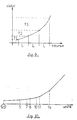
- FIG. 9 illustrates the result obtained when the slide 26 is moved in the body 25 to vary the water flow supplying the snow cannon connected at the outlet of the distributor. Is obtained, through the use of snow cannons according to patent EP-18 280 of the applicant, a proportion of flow rate, substantially constant, regardless of the pressure of the water flow.
- a proportion of flow rate substantially constant, regardless of the pressure of the water flow.
- three types of snow cannons Y1, Y2, Y3 are situated, the flow rates of which can vary from simple to double.
- the small barrel Y1 has a flow rate which can vary from 2.5 to 5 m 3 / h
- the medium barrel Y2 has a flow rate which can vary from 5 to 10 m 3 / h
- the large barrel Y3 has a flow rate which can vary from 10 to 20 m3 / h.
- the pavilion 60 is divided into a certain number of sectors in the form of a truncated cone, between the edge 90 of the body and the plane d entry 91 of said pavilion 60.
- An exemplary embodiment of pavilion 60 is shown in FIG. 10 where, as a function of the distance from the edge 90, expressed in units of length, appears the half-angle at the top of the truncated cones successive.
- the half-angle is 1.8 °; from five to seven units of edge 90, the half angle is 2.6 °; from seven to eight units of the edge, the half angle is 8.8 °; from eleven to fourteen units of the edge, the half-angle is 45 ° and the truncated cone is connected to the annular part 59 of the inlet pipe 56.
- the connection angles, between the truncated cones, are rounded to achieve better continuity of the profile of the roof 60.
- the fourteen length units correspond substantially to the radius of the shutter 81.
- Stroke C of the drawer is broken down into a series of successive stages; at each stage, which corresponds to a very specific portion of the stroke, a particular function of the distributor appears and all of the functions are linked automatically, with great precision and perfect security.
- a first step after a stroke C1 corresponds to the loss of tightness of the flow air; the seal 76 of the shutter 75 has passed from an active sealing position on the envelope 50 of the cylindrical passage 47 to an inactive sealing position at the chamfer 48.
- the next step, after a full stroke C2 corresponds to the closing of the drain, by placing the seal 69 of the rod 67 in the active position, in the cylindrical cavity 87 of the drawer 26.
- the distance which separates, on the body 25, the seal 69, edge 92, chamfer 48, bordering the envelope 50 of passage 47, is greater than the distance which separates, on slide 26, seal 76 from edge 93, at the entrance to the cylindrical cavity 87; this difference provides a delay in closing the purge, relative to the opening of the air flow, and, conversely, it provides an advance at the opening of the purge, relative to the closing of the air flow d air, when the drawer 26 goes from Il to I.
- the seal 82 of the shutter 81, of the slide 26 passes from the active sealing position, downstream of the edge 90, of the body, to the inactive sealing position, upstream of said edge 90
- the distance which separates, on the body 25, the seal 69, from the edge 90 is substantially less, and at the limit equal, to the distance which separates, on the slide 26, the seal 82, of the edge 93, at the entrance to the cylindrical cavity 87.
- the distance separating, on the body 25, the edges 90 and 92 is greater than the distance separating, on the slide 26, the seals 82 and 76.
- the next step corresponds to the passage of a useful flow of water through the body 25; from this stage, and up to the extreme position II of total opening of the water and air flows, the drawer is moved according to the type of snow cannon used, to laminate the flow and not give the cannon only a specific amount of water.
- This quantity of water is determined by the central management computer 6, according to the type of barrel, according to the temperature near the barrel. Obtaining the water flow rate determined by the computer 6 is effected by a displacement of the slide 26 and more particularly of its edge 85, in the pavilion 60. Taking into account that in the water supply to the cannons according to patent EP-18 280, the relationship between the flow and the pressure responds to a well-established law, the control of the flow of water supplying the snow cannon is carried out by means of the pressure sensor positioned in the orifice 70 of the tube 17 for the outlet of the water flow towards the snow cannon.
- the central management computer includes a snowmaking program for the ski slope (s) near which the snow cannons are placed.
- the atmospheric conditions are noted from place to place and more particularly at the level of each shelter 4 where at least one snow cannon is placed.
- the temperature and humidity sensors are connected to the electronic conversion module 41 which is arranged in the housing 24 of the supply device 14 for the snow cannons.
- the information from the temperature and humidity sensors is transformed by the electronic conversion module 41, to be transmitted digitally to the central computer 6, via a simple telephone line 8, to which all the modules are connected.
- Line 8 is connected to the computer by an interface 7 which transforms new digital information 6.
- the electronic conversion module also transmits to the central computer 6, information on the state of the purposes of stroke of the dispenser drawer 26. Each packet of information arrives with the address of the sender and the computer 6 stores this information.
- the central computer 6 When, depending on the planned snow program, the temperature and humidity conditions are reached, the central computer 6 first of all causes the pumps, compressors and their pumps to be started up in the engine room. auxiliaries. This start-up is carried out via the power outputs of an electronic conversion module of the same type as that used by the power supply devices 14, and via the same telephone line 8, which provides one or more machine rooms, as appropriate.
- the electronic engine room conversion module informs the computer 6 of the state of the machines and of the water temperature for example.
- the computer also controls the possible reheating of the bodies 25 of each supply device 14.
- the central computer 6 returns to the ad hoc modules 41, that is to say where the snow conditions are favorable, opening orders of the corresponding drawer dispensers.
- Each electronic conversion module 41 controls, by its power output 12, the gear motor 30 for operating the drawer 26.
- the drawer 26 is moved in the body 25, until a water flow rate is established, in the snow cannon, in relation to the atmospheric conditions of the location of the cannon.
- the control of the flow is carried out by means of a pressure sensor placed in the tube 17 for the outlet of the water flow from the distributor.
- the sensor information is transmitted via the electronic conversion module 41 to the central computer 6 which, in return, gives the orders to maintain the position of the drawer 26 or to change it.
- the computer gives an order which allows, thanks to a preset stroke of the drawer 26, to open the air flow; the water flow is then adjusted, and also according to the evolution of atmospheric conditions.
- the central computer 6 controls the stopping of the snow gun (s), in activity, by giving the electronic conversion modules 41 concerned, the orders closing.
- Each module 41 concerned acts by its logic output 12 of power, on the gear motor 30, to maneuver the slide 26 so as to bring it into the closed position for the flows of water and air and to open the purge, to drain the barrel water circuit.
- the distributor control member can be constituted by a pneumatic or hydraulic system controlled in the same way.
- the dimensions of the body of the dispenser and of the drawer can vary, these dimensions in the example described relate to a concern for minimum bulk, facilitating, moreover, the machining operations.
- the invention can also find other fields of application and more particularly the fields related to the protection of nature and plants, wherever it is advantageous to use an automatic watering or spraying installation.
Abstract
Description
La présente invention concerne un perfectionnement aux dispositifs d'alimentation de canons à neige dans les installations d'enneigement artificiel des pistes de ski, telles que décrites par exemple dans les brevets US-A-3 706 414, 3 372 872, ou encore 2 676 471.The present invention relates to an improvement to the devices for feeding snow cannons in the artificial snowmaking installations of ski slopes, as described for example in patents US-A-3,706,414, 3,372,872, or else 2. 676,471.
L'enneigement artificiel des pistes de ski est réalisé de façon connue par la pulvérisation sur l'emplacement prévu, d'un mélange d'air et d'eau sous la forme d'un brouillard, dans l'air ambiant à basse température au moyen d'un canon à neige et, pour la présente installation selon l'invention, au moyen de canons à neige tels que décrits dans le brevet EP-18 280 de la demanderesse.The artificial snowmaking of ski slopes is achieved in a known manner by spraying on the intended location, a mixture of air and water in the form of a mist, in the ambient air at low temperature at by means of a snow cannon and, for the present installation according to the invention, by means of snow cannons as described in patent EP-18,280 of the applicant.
Dans les installations actuelles d'enneigement artificiel, l'eau et l'air sous pression sont distribués par des conduites longeant toutes les pistes à enneiger. Une installation de ce type est décrite dans le brevet US-A-3 706 414 où apparaissent, en particulier, les moyens de fabrication de la neige. Dans ce document, on remarque que les débits d'eau et d'air sous pression sont réglés au moyen de vannes distinctes, indépendantes l'une de l'autre l'eau et l'air sont ensuite mélangés et évacués par une ou deux buses. Il est fréquent, avec un tel dispositif de commande de l'eau et de l'air, de rencontrer des difficultés de réglage des débits, ce qui provoque des incidents du genre congélation de l'eau, en aval de la vanne, ou encore aspersion de la piste avec de l'eau qui forme une couche de glace. Parfois des abris disposés le long des conduites et espacés de trente à cinquante mètres environ, permettent d'effectuer les branchements des canons à neige.In current artificial snowmaking installations, water and pressurized air are distributed by pipes running along all the snow-covered slopes. An installation of this type is described in US Pat. No. 3,706,414 where, in particular, the means for manufacturing snow appear. In this document, we note that the flow rates of water and air under pressure are regulated by means of separate valves, independent of each other, the water and the air are then mixed and evacuated by one or two nozzles. It is common, with such a water and air control device, to encounter difficulties in adjusting the flow rates, which causes incidents of the freezing type of water, downstream of the valve, or else sprinkling the track with water which forms a layer of ice. Sometimes shelters placed along the pipes and spaced about thirty to fifty meters, make it possible to connect the snow cannons.
L'évolution des techniques a permis d'envisager une évolution dans la gestion des installations d'enneigement des pistes de ski; le document EP-A-0 004 803 brosse les possibilités de ces évolutions et, sur le terrain on a effectivement mis en oeuvre des moyens nouveaux.The evolution of techniques has made it possible to envisage an evolution in the management of snowmaking facilities on ski slopes; document EP-A-0 004 803 outlines the possibilities of these developments and, in the field, new means have actually been implemented.
Le choix des pistes et la mise en route de l'installation sont décidés par un ordinateur central qui prend en compte la température, de place en place, le long de la piste. La seule opération manuelle préalable résulte du choix des canons qui seront utilisés pour recharger tel ou tel sec teur de la piste particulièrement érodé par exemple; cette opération manuelle consiste à ouvrir les vannes pour l'air et pour l'eau dans chaque abri sélectionné, avant d'autoriser la mise en service de l'installation.The choice of tracks and the start-up of the installation are decided by a central computer which takes into account the temperature, from place to place, along the track. The only prior manual operation results from the choice of cannons which will be used to reload this or that sector of the particularly eroded runway, for example; this manual operation consists in opening the air and water valves in each selected shelter, before authorizing the commissioning of the installation.
Compte-tenu des variations importantes et imprévisibles de la température le long des pistes, il arrive fréquemment que la zone choisie se trouve dans des conditions de température qui ne permettent pas la mise en route de l'installation et celle-ci reste arrêtée alors qu'elle aurait pu fonctionner normalement dans une zone voisine, ou sur une autre piste.Given the large and unpredictable variations in temperature along the tracks, it often happens that the chosen area is in temperature conditions that do not allow the installation to start up and it remains stopped while 'it could have operated normally in a neighboring area, or on another runway.
La présente invention vise à remédier aux inconvénients des installations actuelles.The present invention aims to remedy the drawbacks of current installations.
Un premier but de l'invention est est d'obtenir un dispositif automatique associant une grande precision et une parfaite sécurité dans l'enchainement des ouvertures et fermetures des flux d'eau et d'air. Cette automatisation permet en outre de supprimer les intervention manuelles d'opérateurs dans les abris disposés le long de la piste mettant l'installation en veille; ces interventions manuel les étant le plus souvent pénibles, en raison des conditions climatiques, et très coûteuses.A first object of the invention is to obtain an automatic device combining high precision and perfect security in the sequence of openings and closings of the water and air flows. This automation also makes it possible to eliminate the manual intervention of operators in the shelters arranged along the track putting the installation on standby; these manual interventions being them most often painful, because of the climatic conditions, and very expensive.
Il est également alors possible d'utiliser au mieux les conditions climatiques et notamment de la température pour pouvoir produire une quantité maximale de neige en tout endroit des pistes; il est notamment connu que la température a une grande influence sur la quantité de neige produite, et que cette quantite produite par un canon pour une température de -4°, peut être pratiquement doublée, pour une température de -20°.It is also then possible to make the best use of the climatic conditions and in particular of the temperature in order to be able to produce a maximum amount of snow at any location on the slopes; it is notably known that the temperature has a great influence on the quantity of snow produced, and that this quantity produced by a gun for a temperature of -4 °, can be practically doubled, for a temperature of -20 °.
Un autre but de l'invention est de réaliser une installation dont les capacités de production de neige sont fortement multipliées grâce à la possibilité de disposer et de contrôler un nombre très important de canons en bordure des pistes.Another object of the invention is to provide an installation the snow production capacities of which are greatly increased by virtue of the possibility of having and controlling a very large number of guns on the edge of the tracks.
Un autre but important de l'invention est de parvenir à la réalisation d'une installation qui ne constitue pas un investissement prohibitif, compte-tenu du nombre très important de canons qu'il est possible d'utiliser.Another important object of the invention is to achieve the realization of an installation which does not constitute a prohibitive investment, given the very large number of guns that it is possible to use.
Pour atteindre ces buts, l'invention propose un nouveau dispositif d'alimentation de canons à neige; ce dispositif est situé dans chaque abri, le long de la piste, et il est constitué d'un distributeur à tiroir, à fonctions multiples, connecté aux conduites d'eau et d'air sous pression pour alimenter un canon à neige.To achieve these goals, the invention proposes a new device for feeding snow cannons; this device is located in each shelter, along the runway, and it consists of a multi-function drawer distributor connected to the water and pressurized air lines to supply a snow cannon.
Les distributeurs à tiroir sont des organes connus, utilisables dans des applications diverses et sous des formes très variées. Le document FR-A-966 043 par exemple, concerne une application particulière d'un distributeur à tiroir pour la commande automatique des générateurs de chaleur.Drawer distributors are known members, usable in various applications and in very varied forms. The document FR-A-966 043 for example, relates to a particular application of a drawer distributor for the automatic control of heat generators.
Un autre document, le brevet US-A-2 011 329 concerne un distributeur du type robinet mélangeur branché sur des conduites d'eau chaude et d'eau froide.Another document, US Pat. No. 2,011,329 relates to a distributor of the mixer tap type connected to hot and cold water pipes.
Le brevet DE-A-2 551 180 montre un distributeur constitué d'éléments modulaires.Patent DE-A-2,551,180 shows a dispenser made up of modular elements.
Tous ces documents montrent les différentes possibilités d'un distributeur à tiroir, lesquelles possibilités sont exploitées selon l'invention pour lui faire executer les fonctions suivantes:
- - alimentation en air du canon à neige;
- - alimentation en eau du canon à neige;
- - purge du circuit d'alimentation du canon à neige, à partir du distributeur.
- - air supply to the snow cannon;
- - water supply to the snow cannon;
- - purge of the snow cannon supply circuit, from the distributor.
Le dispositif d'alimentation pour canon à neige est situé dans des abris le ou de pistes de ski et ces abris sont traversés par des conduites d'eau et d'air sous pression.The feeding device for snow cannon is located in shelters or ski slopes and these shelters are crossed by water and pressurized air pipes.
Conformément à l'invention, le distributeur à tiroir comprend un corps allonge, muni: de tubulures d'entrées d'eau et d'air connectées aux conduites d'eau et d'air, de tubulures de sorties d'eau et d'air connectées par des tuyauteries au canon à neige, et d'un orifice de purge.According to the invention, the drawer dispenser comprises an elongated body, provided with: water and air inlet pipes connected to the water and air pipes, water and air outlet pipes connected by pipes to the snow cannon, and a purge orifice.
Le distributeur comprend également un tiroir cylindrique muni d'obturateurs cylindriques et entraîné par un organe de commande, de manière à coulisser dans le corps entre une position de fermeture du flux d'eau et d'air dans laquelle la tubulure de sortie d'eau est en communication avec l'orifice de purge, pour assurer une vidange, et une position d'ouverture des flux d'eau et d'air et de fermeture de vidange.The dispenser also includes a cylindrical drawer provided with cylindrical shutters and driven by a control member, so as to slide in the body between a closed position for the flow of water and air in which the water outlet pipe is in communication with the purge orifice, to ensure emptying, and a position for opening the water and air flows and for closing the emptying.
Selon une autre disposition de l'invention, le dispositif d'alimentation comporte des moyens de commande automatique du tiroir du distributeur constitués d'un organe de manoeuvre du tiroir et d'un système d'asservissement de l'organe de manoeuvre.According to another arrangement of the invention, the supply device comprises means for automatic control of the dispenser drawer consisting of a member for operating the drawer and a system for controlling the operating member.
Selon une disposition préférentielle, le flux d'air traverse le corps du distributeur, dans sa partie extrême, située du côté de l'organe de manoeuvre du tiroir, et l'orifice de purge se situe à l'autre extrémité du corps.According to a preferred arrangement, the air flow passes through the body of the distributor, in its extreme part, located on the side of the operating member of the drawer, and the bleed orifice is located at the other end of the body.
Le corps du distributeur comporte des sections cylindriques de passage des flux d'eau et d'air, coopérant avec des obturateurs cylindriques sur le tiroir et, selon une disposition de l'invention, la distance séparant les arêtes amont des sections cylindriques de passage des flux d'eau et d'air dans le corps, est supérieure à la distance séparant les joints d'étanchéité, en rapport, des obturateurs d'eau et d'air sous pression, du tiroir, pour réaliser un retard de l'ouverture d'eau par rapport à l'ouverture l'air.The distributor body has cylindrical sections for the passage of water and air flows, cooperating with cylindrical shutters on the slide and, according to an arrangement of the invention, the distance separating the upstream edges of the cylindrical sections for passage of the flow of water and air in the body, is greater than the distance separating the seals, in relation, from the shutters of water and air under pressure, from the drawer, to achieve a delay of the opening of water relative to the air opening.
Selon une disposition préférentielle de l'invention, l'obturateur d'eau comporte, en aval du joint d'étanchéité, une portion cylindrique réalisant une perte de charge importante et dont la longueur est sensiblement égale au tiers de la course du tiroir, pour établir progressivement le flux d'eau à travers le distributeur.According to a preferred arrangement of the invention, the water shutter comprises, downstream of the seal, a cylindrical portion achieving a significant pressure drop and the length of which is substantially equal to one-third of the drawer stroke, for gradually establish the flow of water through the distributor.
Selon une autre disposition de l'invention, la purge est réalisée au moyen d'une mise en communication de la tubulure de sortie d'eau du distributeur, avec l'extérieur, à travers une cavité cylindrique du tiroir et des orifices de passage, perces à travers le tiroir, et débouchant dans la volute de la tubulure de sortie, laquelle cavité cylindrique est obturée par une tige cylindrique solidaire du corps; la distance séparant le joint d'étanchéité de la tige cylindrique, de l'arête amont de la section de passage du flux d'air, est supérieue à la distance séparant l'arête d'entrée de la cavité cylindrique du tiroir, du joint d'étanchéité de l'obturateur de passage du flux d'air et, la distance séparant le joint d'étanchéité de la tige cylindrique, est inférieure à la distance séparant l'arête d'entrée de la cavité cylindrique du tiroir, du joint d'étanchéité de l'obturateur du passage du flux d'eau, pour réaliser un retard de la fermeture de la purge par rapport à l'ouverture de l'air, ce retard étant toutefois inférieur au retard d'ouverture d'eau par rapport à la même ouverture d'air.According to another arrangement of the invention, the purging is carried out by means of placing the distributor's water outlet tubing in communication with the outside, through a cylindrical cavity of the drawer and through orifices, drilled through the drawer, and opening into the volute of the outlet pipe, which cylindrical cavity is closed by a cylindrical rod secured to the body; the distance separating the seal from the cylindrical rod, from the upstream edge of the air flow passage section, is greater than the distance separating the inlet edge from the cylindrical cavity of the drawer, from the seal of the air flow shutter and, the distance separating the seal from the cylindrical rod, is less than the distance separating the entry edge from the cylindrical cavity of the drawer, of the seal sealing of the shutter of the passage of the water flow, to achieve a delay in the closing of the purge relative to the opening of the air, this delay being however less than the delay in opening the water by compared to the same air opening.
Pour permettre une plus grande efficacité de l'installation face aux conditions de température notamment, le distributeur réalise une fonction complémentaire de réglage automatique du débit d'eau destine au canon.To allow greater efficiency of the installation in the face of temperature conditions in particular, the distributor performs an additional function of automatic adjustment of the water flow intended for the barrel.
Selon l'invention, les moyens de réglage du débit d'eau consistent essentiellement, dans le corps du distributeur, en une partie à section variable, en forme de pavillon, croissante d'aval en amont qui, en coopération avec l'arête aval de l'obturateur de passage du flux d'eau, lamine ledit flux d'eau, avant le passage cylindrique qui est bordé par des arêtes amont et aval.According to the invention, the means for adjusting the water flow essentially consist, in the body of the distributor, in a part with variable section, in the shape of a flag, increasing from downstream to upstream which, in cooperation with the downstream edge of the shutter for the passage of the water flow, laminates the said flow of water, before the cylindrical passage which is bordered by upstream and downstream edges.
Selon une disposition préférentielle de l'invention, le réglage du débit du flux d'eau traversant le distributeur s'effectue, par déplacement contrôlé du tiroir dans le corps du distributeur et la section de passage du flux d'eau est telle que, pour un même déplacement du tiroir, le pourcentage d'accroissement de débit est constant, quelle que soit la pression de l'eau d'alimentation. Cette caractéristique permet d'utiliser le même distributeur pour des canons de types différents et dont les débits peuvent varier dans des proportions importantes, de l'ordre de 1 à 10.According to a preferred arrangement of the invention, the flow rate of the water flow passing through the dispenser is adjusted by controlled movement of the slide in the body of the dispenser and the passage section of the water stream is such that, for the same movement of the slide, the percentage increase in flow is constant, regardless of the pressure of the feed water. This characteristic makes it possible to use the same distributor for barrels of different types and the flow rates of which can vary in significant proportions, of the order of 1 to 10.
Selon une autre disposition de l'invention, le dispositif d'alimentation du canon à neige comporte un organe de manoeuvre du tiroir du distributeur. Cet organe de manoeuvre est constitué d'un moto-réducteur électrique à deux sens de rotation. Ce moto-réducteur agit sur le tiroir, par l'intermédiaire d'une vis s'engageant dans un alésage fileté de l'extrémité du tiroir.According to another arrangement of the invention, the feed device for the snow cannon comprises a member for operating the distributor drawer. This operating member consists of an electric geared motor with two directions of rotation. This gear motor acts on the drawer, by means of a screw engaging in a threaded bore at the end of the drawer.
Selon une autre disposition de l'invention, la vis de manoeuvre du tiroir comporte un roulement de butée permettant de réduire le couple de manoeuvre du tiroir.According to another arrangement of the invention, the drawer operating screw comprises a thrust bearing making it possible to reduce the operating torque of the drawer.
Selon une autre disposition de l'invention, le tiroir est immobilisé, partiellement en rotation, au moyen d'un doigt guidé dans une lumière longitudinale, lequel doigt coopère avec un dispositif indicateur de position du tiroir.According to another arrangement of the invention, the drawer is immobilized, partially in rotation, by means of a finger guided in a longitudinal slot, which finger cooperates with a device indicating the position of the drawer.
Selon une disposition préférentielle de l'invention, l'organe de manoeuvre du tiroir est disposé dans un boîtier solidaire de l'extrémité du corps du distributeur.According to a preferred arrangement of the invention, the operating member of the drawer is arranged in a housing integral with the end of the body of the dispenser.
Le moto-réducteur électrique est commandé, selon l'invention, au moyen d'un système d'asservissement constitué d'un ordinateur central de gestion de l'enneigement des pistes relié par une ligne du genre ligne téléphonique, à des modules électroniques de conversion disposés dans les boîtiers des dispositifs d'alimentation des canons.The electric geared motor is controlled, according to the invention, by means of a servo system consisting of a central computer for managing the snow cover of the tracks connected by a line of the telephone line type, to electronic modules of conversion arranged in the casings of the cannon feeding devices.
Selon l'invention, ces modules électroniques de conversion comportent essentiellement un modem, un convertisseur analogique numérique, des entrées et sorties logiques, le tout géré par un microprocesseur comportant une mémoire morte du type EPROM. Les sorties logiques de puissance sont connectées à l'organe de manoeuvre du tiroir du distributeur les entrées logiques sont connectées à l'indicateur de position et de fin de course disposé dans le boîtier: les entrées analogiques reçoivent les signaux du capteur de pression disposé dans la tubulure de sortie d'eau du distributeur, et des capteurs de température et d'hygrométrie disposés à proximité du canon à neige.According to the invention, these electronic conversion modules essentially comprise a modem, an analog-to-digital converter, logic inputs and outputs, all managed by a microprocessor comprising a read-only memory of the EPROM type. The logic power outputs are connected to the operating element of the distributor drawer the logic inputs are connected to the indicator position and limit switch located in the housing: the analog inputs receive the signals from the pressure sensor placed in the distributor's water outlet pipe, and temperature and humidity sensors arranged near the snow cannon.
L'invention a également pour objet, l'installation qui comprend, d'une part, un tel dispositif d'alimentation de canon à neige et d'autre part, l'ensemble permettant la commande à distance dudit dispositif d'alimentation constitué notamment par les modules électroniques de conversion connectés chacun à une ligne téléphonique unique, oui est reliée à un ordinateur, par l'intermédiaire d'une interface.The subject of the invention is also, the installation which comprises, on the one hand, such a snow-gun feeding device and, on the other hand, the assembly allowing the remote control of said feeding device constituted in particular by the electronic conversion modules each connected to a single telephone line, yes is connected to a computer, via an interface.
Ainsi, l'invention permet une alimentation des canons à neige, sans avoir à déplacer un ou plusieurs opérateurs, auprès de chacun des abris; l'ordinateur central de gestion prend en compte tous les paramètres liés au fonctionnement du ou des canons à neige et, en fonction de ces paramètres, fait un choix parmi les canons et met en service les groupes moto-pompes et moto-compresseurs. L'ordinateur permet également de modifier, en fonction de la température, le débit d'eau de chaque canon et, en fonction du nombre de canons à neige à utiliser, de modifier le choix des canons pour adapter ce choix aux possibilités du groupe moto-pompes et moto-compresseurs.Thus, the invention enables snow cannons to be fed, without having to move one or more operators, to each of the shelters; the central management computer takes into account all the parameters related to the operation of the snow gun (s) and, according to these parameters, makes a choice among the guns and puts into service the motor-pump and motor-compressor groups. The computer also makes it possible to modify, depending on the temperature, the water flow rate of each cannon and, depending on the number of snow cannons to be used, to modify the choice of cannons to adapt this choice to the possibilities of the motorcycle group -pumps and motor-compressors.
L'invention sera mieux comprise à l'aide de la description et des dessins annexés, donnés à titre indicatif et dans lesquels:
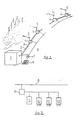
- - la figure 1 est une représentation schématique d'une installation selon l'invention, pour l'enneigement artificiel d'une piste de ski,
- - la figure 2 est une représentation synoptique du module électronique de conversion disposé dans l'abri,
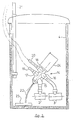
- - la figure 3 est une représentation schématique d'un abri, en coupe, disposé le long de la piste et contenant un dispositif d'alimentation de canon selon l'invention,
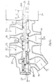
- - la figure 4 est une vue en coupe du distributeur à trioir pour l'alimentation d'un canon à neige,
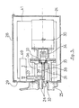
- - la figure 5 est une vue schématique, en coupe de l'organe de manoeuvre du tiroir,
- - la figure 6 est une vue en coupe du corps du distributeur,
- - la figure 7 est une vue avec des coupes partielles du tiroir du distributeur,
- - la figure 8 est une vue partielle, en coupe du distributeur montrant la zone de passage du flux d'eau, sans le dispositif de purge,
- - la figure 9 est une courbe montrant le débit d'eau en fonction de la course utile du tiroir pour trois types de canons différents,
- - la figure 10 représente le profil de la chambre de laminage du corps du distributeur, pour le passage du flux d'eau.
- FIG. 1 is a schematic representation of an installation according to the invention, for artificial snowmaking on a ski slope,
- FIG. 2 is a block diagram of the electronic conversion module placed in the shelter,
- FIG. 3 is a schematic representation of a shelter, in section, arranged along the track and containing a cannon supply device according to the invention,
- FIG. 4 is a sectional view of the sorter distributor for feeding a snow cannon,
- FIG. 5 is a schematic view, in section of the drawer operating member,
- FIG. 6 is a sectional view of the body of the dispenser,
- FIG. 7 is a view with partial sections of the dispenser drawer,
- FIG. 8 is a partial view, in section of the dispenser, showing the zone for the passage of the water flow, without the purge device,
- FIG. 9 is a curve showing the water flow as a function of the useful stroke of the drawer for three different types of guns,
- - Figure 10 shows the profile of the laminating chamber of the distributor body, for the passage of the water flow.
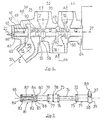
Telle que représentée figure 1, l'installation d'enneigement comporte une salle des machines 1 renfermant les groupes moto-pompes et moto-compresseurs qui alimentent en eau et en air sous pression les conduites 2 et 3 disposées le long de la piste à enneiger.As shown in FIG. 1, the snowmaking installation includes a
Sur les conduites 2 et 3, on trouve des abris 4 espacés de trente à cinquante mètres environ, qui permettent d'une part, de réaliser plus commodément les branchements des canons à neige 5 et, d'autre part, de protéger et maintenir hors gel, ces mêmes branchements et les accessoires liés au fonctionnement des canons 5.On the
Un ordinateur central 6 de gestion de l'enneigement d'une ou plusieurs pistes, est relié par l'intermédiaire d'une interface 7 et d'une ligne spécialisée 8 du type ligne téléphonique à des modules électroniques de conversion représentés figure 2, disposés dans la salle des machines 1 et dans chaque abri 4.A central computer 6 for managing the snowfall of one or more tracks, is connected via an
L'installation comprend encore des capteurs de température et d'hygrométrie non représentés.The installation also includes temperature and humidity sensors not shown.
Ces capteurs sont disposés au niveau de chaque abri 4, tout au long des pistes, à proximité immédiate des canons à neige 5. Les signaux de ces capteurs sont destinés à l'ordinateur 6 qui assure la gestion et la commande de l'enneigement de toutes les pistes. En fonction, notamment, des indications de température reçues, l'ordinateur va choisir le ou les canons pouvant fonctionner; il va également mettre en service, dans la salle des machines 14, les goupes moto-pompes et moto-compresseurs et commander l'alimentation, automatiquement, du ou des canons sélectionnés.These sensors are arranged at each
Le module électronique de conversion est représenté schématiquement figure 2, il est essentiellement constitué d'un modem 9 relié à la ligne téléphonique spécialisée 8, d'un convertisseur analogique numérique 10, d'entrées 11 et de sorties 12 logiques, l'ensemble étant géré par un micro-processeur 13, dont le programme est enregistré dans une mémoire morte du type EPROM. Le convertisseur analogique numérique 10 comporte plusieurs voies d'entrée de signaux analogiques provenant de capteurs de pression, de température, d'hygrométrie. L'entrée logique 11 est reliée au dispositif d'alimentation. Les signaux des capteurs et de l'entrée logique sont transmis à l'ordinateur 6 qui, en retour, et selon son programme d'enneigement, et par l'intermédiaire des sorties logiques 12 du ou des modules électroniques de conversion correspondants, met en action d'une part, les groupes moto-pompes et compresseurs de la salle des machines 1 et d'autre part, le ou les dispositifs d'alimentation 14, représentés figure 3, du ou des canons 5 choisis.The electronic conversion module is represented diagrammatically in FIG. 2, it essentially consists of a modem 9 connected to the
Selon les possibilités de la logique de transmission, on peut disposer d'un nombre d'abris très important. Avec, par exemple, une logique de transmission à huit bits, on peut prevoir 255 abris, ce qui revient à couvrir environ une dizaine de kilomètres. On peut prévoir, également, compte-tenu de la longueur et de l'imbrication des pistes, des dispositifs régénérateurs de signaux.Depending on the possibilities of the transmission logic, there can be a very large number of shelters. With, for example, an eight-bit transmission logic, 255 shelters can be provided, which amounts to covering around ten kilometers. We can also provide, given the length and nesting of the tracks, devices signal regenerators.
La figure 3 représente, schématiquement, un abri 4 traversé par les conduites 2 et 3 d'eau et d'air sous pression. Cet abri 4 renferme un dispositif 14 d'alimentation d'un canon à neige; ce dispositif 14 est branché par ses tubulures d'entrée 15 et 16, sur les conduites d'eau 2 et d'air 3 resprectivement; les sorties 17 et 18 d'eau et d'air du dispositif 14, sont connectées au canon à neige au moyen de tuyauteries souples 19 et 20. Le canon à neige est monté sur une perche 21 solidaire de l'abri.Figure 3 shows, schematically, a
Le dispositif d'alimentation 14 comporte également des moyens permettant de réaliser une purge de la tuyauterie 19 d'alimentation du canon 5 et du canon lui-même. La vidange de la tuyauterie 19 du canon 5 et du dispositif d'alimentation 14 s'effectue par gravité; l'eau s'écoulant par le tuyau 22 dans la conduite de drainage 23 qui récupère les eau de ruissellement à la partie basse de chaque abri 4. Le dispositif d'alimentation 14 est représenté en position inclinée, selon un angle de l'ordre de 45°, pour permettre sa vidange totale par gravité, afin d'éviter tout risque de gel. Il est prévu également de disposer autour, ou dans une cavité, à l'interieur du corps du dispositif d'alimentation 14, un moyen de chauffage non représenté, du type canne, qui permet d'eviter ou d'atténuer les risques de gel. Le module électronique de conversion figure 2, est de préférence logé dans un boîtier 24 disposé dans le prolongement supérieur du dispositif d'alimentation 14.The
Le dispositif d'alimentation 14 est représenté figure 4; il se présente sous la forme d'un distributeur à tiroir, comprenant un corps 25 et un tiroir 26 manoeuvré par des moyens représentés figure 5, lesquels moyens sont disposés dans le boîtier 24.The
Le corps 25 du distributeur est traversé par le flux d'ar (A), le flux d'eau (E) et le flux d'eau de vidange (V). Les entrées et sorties des flux d'eau et d'air sont disposées dans un même plan passant par l'axe longitudinal 27 du corps 25 et du tiroir 26.The
La partie du corps 25, traversee par le flux d'air, se situe de préférence, du côté du boîtier 24 de façon que, en cas de fuite, entre le distributeur et le boîtier, il n'y ait pas de risque d'endommagement des éléments électriques contenus dans ledit boîtier 24. Les différents flux sont séparés par des zones de séparation sur le corps 25, lesquelles zones coopèrent avec des soupapes cylindriques du tiroir 26.The part of the
Le tiroir 26 est représenté en deux moitiés; la moitié 26a est représentée en position active de fermeture des flux d'eau (E) et d'air (A), et d'ouverture du flux de vidange (V) la moitié 26b du tiroir 26 est représentée en position active d'ouverture des flux d'eau (E) et d'air (A) et de fermeture du flux de vidange (V). Entre ce deux positions extrêmes 1 et Il qui correspondent, respectivement, à la position fermée des flux d'eau et d'air et à la position ouverte des mêmes flux d'eau et d'air, la course totale C du tiroir se décompose en une série de portions de courses successives qui correspondent à des mise en oeuvre des différentes fonctions du distributeur.The
Le déplacement du tiroir 26 de la position I à la position Il s'effectue à vitesse très faible, au moyen d'un organe de commande (figure 5), disposé dans le boîtier 24. Ce boîtier 24 comporte une trappe de visite 28 sur le dessus et il est monté sur le corps 25, par l'intermédiaire d'une plaque 29, pour permettre un montage et un démontage plus faciles dudit boîtier 24.The displacement of the
L'organe de manoeuvre du tiroir 26 est constitué d'un moto-réducteur électrique 30, à double sen de rotation, qui entraîne une vis 31 de manoeuvre du tiroir 26, lequel tiroir comporte, axialement, à son extrémité, un alésage fileté 32. La vis 31 est de préférence montée sur un roulement de butée 33, pour réduire le couple de manoeuvre du tiroir 26, et elle est solidaire du moto-réducteur 30, par un accouplement 34. Le support 35 du roulement de butée 33, fixe sur le corps 25 du distributeur, comporte une lumière 36, disposée longitudinalement, dans laquelle coulisse un doigt 37 d'immobilisation partielle en rotation du tiroir 26. La longueur de la lumière 36 est supérieure à la course du tiroir 26. Le doigt 37 est disposé perpendiculairement à l'axe 27, dans une collerette 38, qui constitue l'extrémité 39 du tiroir 26. Le doigt 37 se prlonge au-delà de la lumière 36 pour agir sur un indicateur 40 de position et plus particulièrement de fin de course du tiroir 26. Cet indicateur 40 est logé dans le boîtier 24, sur la plaque frontale 29, solidaire du corps 25 du distributeur.The actuator of the
L'indicateur 40 de fin de course du tiroir est relié au module électronique de conversion 41, disposé dans le boîtier 24 il est connecté à l'entrée logique 11 du module électronique de conversion (figure 2). Cette entrée logique 11 est prévue pour recevoir les informations de deux dispositifs d'alimentation de canon à neige 5.The end-of-
Le corps 25 du distributeur est représenté (figure 6) sans le tiroir 26. Ce corps 25 comporte, à partir de l'extrémité recevant le boîtier 24, une zone cylindrique axiale de séparation 42, entre l'extérieur et le flux d'air (A) et plus particulièrement, la volute de sortie 43 du flux d'air, qui est prolongée par la tubulure de sortie 18; la volute de sortie 43 et la tubulure 18 sont alignées selon un même plan médian 44, perpendiculaire à l'axe longitudinal 27, du corps 25. La tubulure d'entrée 16 du flux d'air (A) se prolonge également par une volute 45, alignées toutes deux, selon un plan médian 46, perpendiculaire à l'axe longitudinal 27, du corps 25. Les deux volutes 43 et 45 sont séparées par un passage axial 47; la longueur du passage d'air 47 est sensiblement égale à la moitié de la course du tiroir. Ce passage 47 comporte, de chaque côté, des chanfreins 48 et 49, qui délimitent une zone cylindrique 50, faisant office de siège; la longueur de cette zone 50 est sensiblement égale à la moitié de la longueur du passage 47.The
Une zone cylindrique axiale 51 sépare les flux d'eau (E) et d'air (A) dans le corps 25; la longueur de cette zone 51 est, dans l'exemple décrit, légèrement supérieure à la course C du tiroir.An axial
Au-delà de cette zone de séparation 51, toujours en s'éloignant du boîtier 24, on trouve une volute de sortie d'eau 52, prolongée par la tubulure de sortie 17; la tubulure 17 et la volute 52 étant alignées, selon un même plan médian 53, perpendiculaire à l'axe longitudinal 27, du corps 25. On trouve ensuite, un passage cylindrique axial 54, du flux d'eau (E) dont l'enveloppe externe 55 constiue le siège d'obturation dudit flux d'eau. La longeur du passage cylindrique du flux d'eau, est sensiblement supérieure à celle de passage cylindrique 47 du flux d'air. En amont du passage cylindrique 54, on trouve la volute d'entrée d'eau 56 qui prolonge la tubulure d'entrée d'eau 15. La tubulure d'entrée d'eau 15 est centrée sur un axe 57 qui fait un angle de l'ordre de 45° avec l'axe longitudinal 27 du corps 25, pour mettre le distributeur en position inclinée, selon la figure 3. Cette position inclinée a pour but de permettre une vidange totale ou quasi totale du corps 25 du distributeur et, plus particulièrement, du fond 58 de la volute de sortie d'eau 52. La partie annulaire 59 de la volute d'entrée d'eau se prolonge par un pavillon 60, jusqu'au passage cylindrique 54. Ce pavillon 60 est centré sur l'axe longitudinal 27 et son rôle sera explicité plus loin. La section du pavillon est décroissante, d'amont en aval, et le profil dudit pavillon sera détaillé, plus loin également.Beyond this
Après la volute d'entrée du flux d'eau 56, on trouve une zone cylindrique axiale de séparation 61 qui isole ladite volute 56 et s'étend jusqu'à l'extrémité du corps 25 du distributeur. L'entrée de la zone cylindrique 61 comporte une collerette 62 qui s'étend dans la partie annulaire 59 de la volute, sur une longueur sensiblement supérieure à la moitié de la longueur axiale de ladite partie annulaire 59. La longueur de la zone cylindrique de séparation 61 est du même ordre que celle de la zone de séparation 42, c'est-à-dire supérieure à la course C du tiroir 26.After the inlet volute of the
L'extrémité 63 du corps 25, à l'opposé de l'extrémité 64 supportant le boîtier 24, comporte un chapeau 65, solidaire de ladite extrémité 63, par tous moyens appropriés. Ce chapeau 65 est muni d'un orifice 66 de vidange communiquant avec l'extérieur, par l'intermédiaire de la tuyauterie 22 (figure 3), qui déverse le flux d'eau de vidange V, dans la conduite 23.The
Pour répondre au souci de vidange totale du corps 25 du distributeur, l'orfice 66 de purge est disposé dans la partie basse du chapeau 65.To respond to the concern of total emptying of the
Le chapeau 65 comporte encore une tige cylindrique 67 centrée sur l'axe longitudinal 27, qui s'étend à l'intérieur de la zone cylindrique de séparation 61. Cette tige 67 est munie à son extrémité d'un obturateur 68 et d'un joint annulaire d'étanchéité 69.The
Le diamètre de l'obturateur 68 est de l'ordre du tiers du diamètre de la zone cylindrique de séparation 61. La longueur séparant le chapeau 65 du joint d'étanchéité 69 est sensiblement supérieure à la course C du tiroir 26. On peut prévoir de réaliser l'extrémité 63 du corps 25, de façon séparée, dudit corps, pour permettre notamment un usinage plus aisé du pavillon 60. Dans ce cas, l'extrémité 63 se présenterait sous la forme d'un manchon cylindrique qui comprendrait toute la zone cylindrique de séparation 61.The diameter of the
Le corps 25 comporte encore, dans la tubulure de sortie 17 du flux d'eau (E), un orifice 70 destiné à récevoir un capteur de pression qui sera relié au module électronique de conversion 41 disposé dans le boîtier 24, et plus particulièrement au convertisseur analogique numérique 10 (figure 2) dudit module électronique de conversion. A noter que le convertisseur analogique numérique 10 peut être prévu pour recevoir les signaux de deux capteurs de pression correspondant à deux dispositifs d'alimentation placés à proximité l'un de l'autre, dans un même abri 4 et qui sont destinés à alimenter deux canons à neige 5.The
Les zones cylindriques de séparation 42, 51, 61 et le passages cylindriques 47, 54, sont centrés sur l'axe longitudinal 27 du corps 25 et le diamètre de ces zones et de ces passages, est de préférence identique.The
Le tiroir 26 qui se déplace dans les zones de séparation 42,51,61 et les passages 47, 54, est représenté figure 7.The
En partant de l'extrémité 39 du tiroir 26, on trouve la collerette cylindrique 38 dans laquelle est positionné le doigt 37 d'immobilisation partielle en rotation du tiroir. Le diamètre de la collerette 38 est sensiblement supérieur au diamètre de la zone de séparation 42 du corps 25.Starting from the
Cette collerette se prolonge ensuite par une tige cylindrique 71 d'un diamètre sensiblement inférieur au diamètre de la zone de séparation 42 du corps 25 et d'une longueur environ égale à la course C du tiroir. Au bout de cette tige 71, on trouve un obturateur 72 muni d'un joint annulaire d'étanchéité 73. Cet obturateur 72 se situe dans la zone de séparation 42 du corps 25 et isole en permanence, la volute 43 de sortie du flux d'air de l'extérieur, côté boîtier 24.This collar is then extended by a
Au-delà de l'obturateur 72, on trouve une tige 74 dont le diamètre est voisin de la moitié du diamètre de l'obturateur 72 et dont la longueur est égale à la course C augmentée au moins de la longueur axiale de la volute 43 de sortie du flux d'air au niveau de l'axe 27 du corps 25.Beyond the
La tige 74 relie l'obturateur 72 à un obturateur 75 cylindrique et de même diamètre. Cet obturateur 75 a deux fonctions essentielles: il assure la fermeture du passage 47 du flux d'air A, coupant ainsi l'alimentation en air du canon à neige, et il assure l'isolation entre les flux d'air A et d'eau E, et plus particulièrement l'isolation entre l'arrivée du flux d'air A au niveau de la volute 45 et le départ du flux d'eau E, au niveau de la volute 52 du corps 25.The
L'obturateur 75 comporte deux joints annulaires 76 et 77 disposés à chacune de ses extrémités et un joint annulaire central 78. La distance séparant les deux joints d'extrémité 76 et 77 est sensiblement égale à la course C du tiroir 26.The
Au-delà de l'obturateur 75, on trouve une nouvelle tige cylindrique 79 dont le diamètre est de l'ordre des deux tiers du diamètre de l'obturateur 75 et dont la longueur est égale, dans l'exemple represénté à deux fois son diamètre. En fait, cette longueur de la tige 79 est en relation avec la longueur de la zone de separation 51 du corps 25.Beyond the
La tige 79 se prolonge par une partie conique 80 qui raccorde ladite tige à un obturateur cylindrique 81. Le demi-angle au sommet de la partie conique est de l'ordre de 45°. L'obturateur cylindrique 81 réalise plusieurs fonctions. Tout d'abord, il comporte deux joints annulaires d'étanchéité 82 et 83, dont l'un, le joint 83 est situé à l'extrémité 84 du tiroir 26. Ce joint annulaire 83 isole en permanence la volute 56 d'entrée d'eau de l'extérieur, en se déplaçant dans la zone cylindrique de séparation 61 du corps 25. Le deuxième joint annulaire d'étanchéité 82 est situé en retrait par rapport à l'arête aval 85 de l'obturateur 81, au niveau de la partie conique 80; la distance séparant le joint 82 de l'arête 85 est sensiblement égale au rayon de l'obturateur 81. Le rôle de la zone cylindrique 86 située entre le joint 82 et l'arête 85 de l'obturateur 81 sera explicité plus loin.The
L'obturateur 81 comporte également un alésage cylindrique axial 87 qui débouche, par l'intermédiaire d'au moins un orifice percé 88, dans la partie conique de raccordement 80. De préférence, on dispose de plusieurs orifices 88, dont l'axe de l'un est disposé dans le plan qui passe par l'axe 89 du doigt 37 de positionnement du tiroir 26, par rapport au corps 25, cet axe 89 se situant dans le plan passant par l'axe longitudinal 27 du corps 25 et par l'axe 57 de la tubulure 15 d'entree du flux d'eau.The
Les deux extrémités 38 et 84 du tiroir 26 communiquant avec l'extérieur, ce qui permet de l'équilibrer et de réduire les efforts pour son déplacement dans le corps 25.The two ends 38 and 84 of the
La figure 8 représente, de façon détaillée et en coupe, la partie du distributeur à tiroir traversée par le flux d'eau E. Cette partie comporte des moyens qui permettent de réaliser plusieurs fonctions et notamment une fonction obturation et une fonction réglage du débit d'eau.FIG. 8 shows, in detail and in section, the part of the spool valve crossed by the water flow E. This part comprises means which make it possible to perform several functions and in particular a shutter function and a function for adjusting the flow rate d 'water.
Le tiroir 26 est représenté en deux moitiés 26a et 26b; la partie 26a du tiroir est en position d'obturation de l'arrviee d'eau E; la partie 26b est en position d'ouverture de l'arrivée d'eau E.The
L'arrêt du flux d'eau E, à travers le corps 25, s'effectue au moyen de l'obturateur 81 et de ses deux joints annulaires d'étanchéité 82 et 83 qui sont, respectivement, en position active, sur l'enveloppe 55 du passage cylindrique 54 et sur la paroi 89 de la zone cylindrique de separation 61.The flow of water E through the
Le réglage du débit d'eau traversant le corps 25, s'effectue par laminage du flux d'eau entre l'arête 85 de l'obturateur 81 et le pavillon 60 qui prolonge la partie annulaire 59 de la volute 56 et précède le passage cylindrique 54. La section de passage du flux d'eau entre le pavillon 60 et l'arête 85, varie au fur et à mesure du déplacement du tiroir 26, dans le corps 25, du distributeur.The water flow through the
La course utile du tiroir pour le réglage du débit d'eau, commence lorsque l'arête 85 de l'obturateur 81 arrive au niveau de l'arête fictive 90 séparant le pavillon 60 et le passage cylindrique 54, et elle se termine lorsque l'arête 85 approche du plan vertical 91 d'entrée du pavillon 60.The useful stroke of the drawer for adjusting the water flow rate begins when the
Entre les positions de l'obturateur 81, où le joint d'étanchéité 82 est en position inactive d'étanchéité, c'est-à-dire dispose en amont de l'arête 90 du corps, et où l'arête 85 atteint l'arête 90, une perte de charge importante est réalisée dans le passage cylindrique 54, entre son enveloppe 55 et la partie cylindrique 86 de l'obturateur 81. Cette perte de charge varie au fur et à mesure du déplacement du tiroir 26 et permet un établissement progressif du débit utile d'eau, à travers le corps. La détente du flux en aval de l'arête 85, s'effectue avec un niveau sonore très faible et, à pleine ouverture, la perte de charge est minime.Between the positions of the
Lorsque le débit d'eau commence à s'établir à travers le corps 25, c'est-à-dire lorsque l'arête 85 de l'obturateur 81 se situe en amont de l'arête 90, dudit corps 25, le joint d'étanchéité 82 dudit obturateur 81 se situe nettement en amont dans le pavillon 60, et suffisamment en retrait pour ne pas risquer d'être arraché par le flux d'eau. Lorsque les débits importants sont atteints, c'est-à-dire lorsque le tiroir 26 est en position de grande ouverture, le joint d'étanchéité 82 est protégé en pénétrant dans la zone cylindrique de séparation 61 et plus particulièrement dans la collerette 62 qui est disposée dans le prolongement de ladite zone de séparation 61. Le joint d'étanchéité 82 sera de préférence un joint à haute résistance mécanique.When the water flow begins to establish through the
La figure 9 illustre le résultat obtenu lorsque le tiroir 26 est déplacé dans le corps 25 pour faire varier le débit d'eau alimentant le canon à neige branché en sortie du distributeur. On obtient, grâce à l'emploi de canons à neige selon le brevet EP-18 280 de la demanderesse, une proportion de débit, sensiblement constante, quelle que soit la pression du flux d'eau. A titre d'exemple, sur la figure 9, on a situé trois types de canons a neige Y1, Y2, Y3 dont les débits peuvent varier du simple au double.FIG. 9 illustrates the result obtained when the
Ainsi, le petit canon Y1 a un débit pouvant varier de 2,5 à 5 m3/h, le canon moyen Y2 a un débit pouvant varier de 5 à 10 m3/h et le gros canon Y3 a un débit pouvant varier de 10 à 20 m3/h.Thus, the small barrel Y1 has a flow rate which can vary from 2.5 to 5 m 3 / h, the medium barrel Y2 has a flow rate which can vary from 5 to 10 m 3 / h and the large barrel Y3 has a flow rate which can vary from 10 to 20 m3 / h.
On constate, figure 9, que la variation de débit des différents types de canons Y1, Y2, Y3 s'effectue avec une même course utile L du tiroir 26, dans le corps 25 du distributeur. Cette possibilité de faire varier le débit automatiquement pour chaque canon, permet de profiter, au maximum, des conditions favorables de température et, notamment de doubler la quantité de neige produite, lorsque la température passe de -4° à -20°C par exemple.It can be seen, in FIG. 9, that the variation in flow rate of the different types of guns Y1, Y2, Y3 takes place with the same useful stroke L of the
Ce résultat est plus particulièrement obtenu par le profil du pavillon 60, du corps 25. Le pavillon 60, figure 8, est divisé en un certain nombre de secteurs en forme de tronc de cône, entre l'arête 90 du corps et le plan d'entrée 91 dudit pavillon 60. Un exemple de réalisation du pavillon 60 est représenté figure 10 où apparaît, en fonction de la distance par rapport à l'arête 90, exprimée en unités de longueur, le demi-angle au sommet des troncs de cône successifs. Ainsi, depuis l'arête 90 et sur une distance de cinq unités, le demi-angle fait 1,8° ; de cinq à sept unités de l'arête 90, le demi-angle fait 2,6°; de sept à huit unités de l'arête, le demi-angle fait 8,8° ; de onze à quatorze unités de l'arête, le demi-angle fait 45° et le tronc de cône se raccorde à la partie annulaire 59 de la tubulure d'entrée 56. Les angles de raccordement, entre les troncs de cône, sont arrondis pour réaliser une mellieure continiuté du profil du pavillon 60. Les quatorze unités de longeur correspondent sensiblement au rayon de l'obturateur 81.This result is more particularly obtained by the profile of the
Le fonctionnement du distributeur et plus particulièrement la mise en oeuvre des fonctions du distributeur à tiroir est le suivant:The operation of the distributor and more particularly the implementation of the functions of the drawer distributor is as follows:
La course C du tiroir se décompose en une série d'étapes successives; à chaque étape, qui correspond à une portion de course bien précise, une fonction particulière du distributeur apparaît et l'ensemble des fonctions s'enchaîne automatiquement, avec une grande précision et une parfaite sécurité.Stroke C of the drawer is broken down into a series of successive stages; at each stage, which corresponds to a very specific portion of the stroke, a particular function of the distributor appears and all of the functions are linked automatically, with great precision and perfect security.
Ainsi, en partant de la position I, figure 4, c'est-à-dire de la position fermée des flux d'eau et d'air, une première étape après une course C1, correspond à la perte d'étanchéité du flux d'air; le joint 76 de l'obturateur 75 est passé d'une position active d'étanchéité sur l'enveloppe 50 du passage cylindrique 47 à une position inactive d'etanchéité au niveau du chanfrein 48. L'étape suivante, après une course totale C2, correspond à la fermeture de la purge, par la mise en position active du joint d'étanchéité 69 de la tige 67, dans la cavité cylindrique 87 du tiroir 26. De ce fait, la distance qui sépare, sur le corps 25, le joint d'étanchéité 69, de l'arête 92, du chanfrein 48, bordant l'enveloppe 50 du passage 47, est supérieure à la distance qui sépare, sur le tiroir 26, le joint d'étanchéité 76 de l'arête 93, à l'entrée de la cavité cylindrique 87; cette différence procure un retard de fermeture de la purge, par rapport à l'ouverture du flux d'air, et, à l'inverse, elle procure une avance à l'ouverture de la purge, par rapport à la fermeture du flux d'air, lorsque le tiroir 26 va de Il à I.Thus, starting from position I, FIG. 4, that is to say from the closed position of the water and air flows, a first step after a stroke C1, corresponds to the loss of tightness of the flow air; the
L'étape qui suit, après une course totale C3, correspond à la perte d'étanchéité du flux d'eau; le joint d'étanchéité 82 de l'obturateur 81, du tiroir 26, passe de la position active d'étanchéité, en aval de l'arête 90, du corps, à la position inactive d'étanchéité, en amont de ladite arête 90. D'une part, la distance qui sépare, sur le corps 25, le joint d'étanchéité 69, de l'arête 90, est sensiblement inférieure, et à la limite égale, à la distance qui sépare, sur le tiroir 26, le joint d'étanchéité 82, de l'arête 93, à l'entrée de la cavité cylindrique 87. D'autre part, la distance séparant, sur le corps 25, les arêtes 90 et 92, est supérieure à la distance séparant, sur le tiroir 26, les joints 82 et 76. Ces dispositions realisent, automatiquement, un retard d'ouverture du flux d'eau par rapport à l'ouverture du flux d'air et par rapport à la fermeture de la purge. A l'inverse, ces dispositions réalisent une avance de fermeture du flux d'eau par rapport à l'ouverture de la purge et à la fermeture du flux d'air, lorsque le tiroir 26 passe de la position Il à la position I.The following step, after a total stroke C3, corresponds to the loss of water flow tightness; the
L'étape suivante, apres une course totale C4, correspond au passage d'un débit utile d'eau à travers le corps 25; à partir de cette étape, et jusqu'à la position extrême Il d'ouverture totale des flux d'eau et d'air, le tiroir est déplacé en fonction du type de canon à neige utilise, pour laminer le flux et ne donner au canon qu'une quantité d'eau déterminée.The next step, after a total stroke C4, corresponds to the passage of a useful flow of water through the
Cette quantité d'eau est déterminée par l'ordinateur central de gestion 6, selon le type de canon, selon la température à proximité du canon. L'obtention du débit d'eau déterminé par l'ordinateur 6 s'effectue par un déplacement du tiroir 26 et plus particulièrement de son arête 85, dans le pavillon 60. Compte-tenu du fait que dans l'alimentation en eau des canons à neige de la demanderesse, selon le brevet EP-18 280, la relation entre le débit et la pression répond à une loi bien établie, le contrôle du débit d'eau alimentant le canon à neige s'effectue au moyen du capteur de pression positionné dans l'orifice 70 de la tubulure 17 de sortie du flux d'eau vers le canon à neige.This quantity of water is determined by the central management computer 6, according to the type of barrel, according to the temperature near the barrel. Obtaining the water flow rate determined by the computer 6 is effected by a displacement of the
Le fonctionnement de l'installation d'enneigement représentée figure 1, et comprenant le dispositif d'alimentation 14, tel que décrit en liaison avec les figures 3 à 10, est le suivant:The operation of the snowmaking installation shown in FIG. 1, and comprising the
L'ordinateur central de gestion comporte un programme d'enneigement de la ou des pistes de ski à proximité desquelles sont disposés les canons à neige.The central management computer includes a snowmaking program for the ski slope (s) near which the snow cannons are placed.
Les conditions atmosphériques sont relevées de place en place et plus particulièrement au niveau de chaque abri 4 où est disposé au moins un canon à neige. Les capteurs de température et d'hygrométrie sont connectés au module de conversion électronique 41 qui est disposé dans le boîtier 24 du dispositif d'alimentation 14 des canons à neige. Les informations des capteurs de température et d'hygrométrie sont transformées par le module électronique de conversion 41, pour être transmises numériquement à l'ordinateur central 6, par l'intermédiaire d'une simple ligne téléphonique 8, sur laquelle sont raccordés tous les modules électroniques de conversion 41, de chaque abri 4. La ligne 8 est reliée à l'ordinateur par une interface 7 qui transforme 6 nouveau les informations numériques. Le module électronique de conversion transmet également à l'ordinateur central 6, des informations sur l'état des fins de course du tiroir 26 du distributeur. Chaque paquet d'informations arrive, avec l'adresse de l'expéditeur et l'ordinateur 6 emmagasine ces informations.The atmospheric conditions are noted from place to place and more particularly at the level of each
Lorsque, en fonction du programme d'enneigement prévu, les conditions de température et d'hygrométrie sont atteintes, l'ordinateur central 6 provoque tout d'abord la mise en marche, dans la salle des machines, des pompes, compresseurs et de leurs auxiliaires. Cette mise en marche s'effectue par l'intermédiaire des sorties de puissance d'un module électronique de conversion du même type que celui utilisé par les dispositifs d'alimentation 14, et par l'intermédiaire de la même ligne téléphonique 8, ce qui permet de disposer d'une ou de plusieurs salles de machines, selon le cas. Le module électronique de conversion de la salle des machines informe l'ordinateur 6 de l'état des machines et de la température de l'eau par exemple.When, depending on the planned snow program, the temperature and humidity conditions are reached, the central computer 6 first of all causes the pumps, compressors and their pumps to be started up in the engine room. auxiliaries. This start-up is carried out via the power outputs of an electronic conversion module of the same type as that used by the
L'ordinateur commande également le réchauffage éventuel des corps 25 de chaque dispositif d'alimentation 14.The computer also controls the possible reheating of the
Lorsque le conduites 2 et 3 d'eau et d'air sous pression sont en charge, l'ordinateur central 6 retourne aux modules 41 ad hoc, c'est-à-dire là où les conditions pour l'enneigement sont favorables, des ordres d'ouverture des distributeurs à tiroirs correspondants. Chaque module électronique de conversion 41 commande, par sa sortie de puissance 12, le moto-réducteur 30 de manoeuvre du tiroir 26. Le tiroir 26 est déplacé dans le corps 25, jusqu'à l'etablissement d'u débit d'eau, dans le canon à neige, en rapport avec les conditions atmosphériques du lieu du canon. Le contrôle du débit est effectué par l'intermédiaire d'un capteur de pression disposé dans la tubulure 17 de sortie du flux d'eau du distributeur. Les informations du capteur sont transmises par l'intermédiaire du module électronique de conversion 41, à l'ordinateur central 6 qui, en retour, donne les ordres pour maintenir la position du tiroir 26 ou la modifier. Pour la mise en marche de départ du canon à neige, l'ordinateur donne un ordre qui permet, grace à une course préétablie du tiroir 26, d'ouvrir le flux d'air; le réglage du débit d'eau s'effectuant ensuite, et aussi selon l'évolution des conditions atmosphériques.When the
Lorsque la quantité de neige programmée est atteinte, ou lorsque les conditions atmosphériques ne sont plus favorables, l'ordinateur central 6 commande l'arrêt du ou des canons à neige, en activité, en donnant aux modules électroniques de conversion 41 concernés, les ordres de fermeture. Chaque module 41 concerné agit par sa sortie logique 12 de puissance, sur le moto-réducteur 30, pour manoeuvrer le tiroir 26 de façon à l'amener en position de fermeture des flux d'eau et d'air et d'ouverture de la purge, pour vidanger le circuit d'eau du canon.When the programmed amount of snow is reached, or when the atmospheric conditions are no longer favorable, the central computer 6 controls the stopping of the snow gun (s), in activity, by giving the
L'invention ne se limite pas au mode de réalisation décrit.The invention is not limited to the embodiment described.
C'est ainsi que l'organe de commande du distributeur peut être constitué d'un système pneumatique ou hydraulique asservi de la même façon. De même les dimensions du corps du distributeur et du tiroir peuvent varier, ces dimensions dans l'exemple décrit relèvent d'un souci d'encombrement minimum facilitant, par ailleurs, les opérations d'usinage.Thus the distributor control member can be constituted by a pneumatic or hydraulic system controlled in the same way. Likewise, the dimensions of the body of the dispenser and of the drawer can vary, these dimensions in the example described relate to a concern for minimum bulk, facilitating, moreover, the machining operations.
L'invention peut également trouver d'autres domaines d'application et plus particulièrement les domaines liés à la protection de la nature et des végétaux, partout ou l'on a avantage à utiliser une installation automatique d'arrosage ou de pulvérisation.The invention can also find other fields of application and more particularly the fields related to the protection of nature and plants, wherever it is advantageous to use an automatic watering or spraying installation.
Claims (26)
Priority Applications (1)
| Application Number | Priority Date | Filing Date | Title |
|---|---|---|---|
| AT85402297T ATE41224T1 (en) | 1984-11-27 | 1985-11-25 | POWER SUPPLY DEVICES FOR SNOW GUNS IN SYSTEMS FOR ARTIFICIAL SNOW SUPPLY FOR SKI SLOPES. |
Applications Claiming Priority (2)
| Application Number | Priority Date | Filing Date | Title |
|---|---|---|---|
| FR8418236 | 1984-11-27 | ||
| FR8418236A FR2573854B1 (en) | 1984-11-27 | 1984-11-27 | IMPROVEMENT IN SNOW CANNON FEEDING DEVICES IN ARTIFICIAL SNOW PLANTS FOR SKI SLOPES |
Publications (2)
| Publication Number | Publication Date |
|---|---|
| EP0187563A1 EP0187563A1 (en) | 1986-07-16 |
| EP0187563B1 true EP0187563B1 (en) | 1989-03-08 |
Family
ID=9310087
Family Applications (1)
| Application Number | Title | Priority Date | Filing Date |
|---|---|---|---|
| EP85402297A Expired EP0187563B1 (en) | 1984-11-27 | 1985-11-25 | Snow gun feeding devices in systems for providing ski slopes with artificial snow |
Country Status (8)
| Country | Link |
|---|---|
| US (1) | US4717072A (en) |
| EP (1) | EP0187563B1 (en) |
| JP (1) | JPS61197971A (en) |
| AT (1) | ATE41224T1 (en) |
| CA (1) | CA1298477C (en) |
| DE (2) | DE3568629D1 (en) |
| ES (1) | ES8708050A1 (en) |
| FR (1) | FR2573854B1 (en) |
Families Citing this family (24)
| Publication number | Priority date | Publication date | Assignee | Title |
|---|---|---|---|---|
| FR2579732B1 (en) * | 1985-03-27 | 1987-09-25 | Ene Ste Civile | DEVICES AND METHODS FOR MANUFACTURING ARTIFICIAL SNOW |
| FR2623276A1 (en) * | 1987-11-12 | 1989-05-19 | York Froid Ind | Protective housing for an automatic snow-making installation |
| FR2634663A1 (en) * | 1988-07-29 | 1990-02-02 | Lagier Jacques | Installation for covering ski runs with artificial snow |
| US5031832A (en) * | 1990-01-26 | 1991-07-16 | Ratnik Industries Inc. | Automated snow-making system |
| FR2667681B1 (en) * | 1990-10-03 | 1993-01-08 | York Froid Ind | IMPROVEMENT IN SHELTERS FOR AUTOMATIC SNOWFALL INSTALLATIONS. |
| IT1259262B (en) * | 1992-07-31 | 1996-03-11 | AUTOMATIC LOW PRESSURE SYSTEM FOR DINEVE SCHEDULED PRODUCTION | |
| JPH0682134A (en) * | 1992-09-03 | 1994-03-22 | Kajima Corp | Method and apparatus for making artificial snow |
| AU730609B2 (en) * | 1992-09-09 | 2001-03-08 | Sims Deltec, Inc. | Systems and methods for communicating with ambulatory medical devices such as drug delivery devices |
| DE4243731C1 (en) * | 1992-12-23 | 1994-05-11 | Manfred Weinrich | Snow-generating gun for ski slopes - controls water-supply valve electronically dependent on difference between temperatures detected by two sensors |
| US5749517A (en) * | 1995-09-27 | 1998-05-12 | Dupre; Herman K. | Control system for snow making devices |
| US5718378A (en) * | 1995-09-27 | 1998-02-17 | Dupre; Herman K. | Control system for snow making devices |
| US6374848B1 (en) * | 1999-04-15 | 2002-04-23 | Mcghee John D. | Automatic mechanism for cut-off and drainage of under low-freezing ambient temperature conditions |
| FR2795494B1 (en) * | 1999-06-25 | 2001-09-14 | York Neige | VALVE FOR THE DISTRIBUTION OF WATER AND ANY AIR, IN PRESSURIZED WATER SPRAYING INSTALLATIONS, FOR EXAMPLE FOR THE MANUFACTURE OF SNOW |
| US6554200B1 (en) * | 2000-11-01 | 2003-04-29 | Kabushiki Kaisha Piste Snow Industries | System and method for remotely monitoring artificial snow maker of ice crushing type |
| FR2877076A1 (en) * | 2004-10-27 | 2006-04-28 | Snowstar | Artificial snow producing device e.g. snow gun, has head with main supply pipe extending along head`s height and secondary pipes connecting fluid outlets to main pipe, and valve inserted between each outlet having two nozzles, and main pipe |
| WO2006076458A1 (en) * | 2005-01-13 | 2006-07-20 | Santry Charles N | Freeze-proof water valve for supplying secondary water to a snow making apparatus |
| FR2914989B1 (en) * | 2007-04-13 | 2009-07-24 | Johnson Controls Neige Soc Par | SNOW PLANT AND STACK FOR SUCH INSTALLATION. |
| FR2950124B1 (en) | 2009-09-17 | 2011-12-09 | Johnson Controls Neige | VALVE FOR THE DISTRIBUTION OF WATER AND AIR IN PRESSURE WATER SPRAY FACILITIES |
| ITVR20120193A1 (en) | 2012-09-28 | 2014-03-29 | Technoalpin A G S P A | CONTROL SYSTEM FOR AN ARTIFICIAL WINTER SYSTEM |
| CA2979684A1 (en) * | 2015-03-13 | 2016-09-22 | Snow Logic, Inc. | Dual auto hydrant for snowmaking gun and method of using same |
| CA2981878C (en) | 2015-04-06 | 2023-11-14 | Snow Logic, Inc. | Snowmaking automation system and modules |
| EP3672823B1 (en) | 2017-09-14 | 2023-07-19 | Agility Fuel Systems LLC | Systems for monitoring volatile fuel system components |
| US10942533B2 (en) * | 2018-02-14 | 2021-03-09 | Hexagon Technology As | System for multiple pressure relief device activation |
| EP4031799A4 (en) | 2019-11-25 | 2023-10-25 | Agility Fuel Systems LLC | Improved pressure relief device |
Family Cites Families (21)
| Publication number | Priority date | Publication date | Assignee | Title |
|---|---|---|---|---|
| US584682A (en) * | 1897-06-15 | Water-plug | ||
| US979941A (en) * | 1910-08-19 | 1910-12-27 | John Lansing Fuller | Hydrant and valve therefor. |
| US1276677A (en) * | 1917-06-13 | 1918-08-20 | Saul Mittleburg | Bracket. |
| US2011329A (en) * | 1935-02-19 | 1935-08-13 | Wayer Henry | Faucet |
| FR966043A (en) * | 1948-05-05 | 1950-09-28 | Spool valve for automatically controlling the heating and cooling circuits of generators using special liquids as heat vehicles | |
| US3080952A (en) * | 1958-11-25 | 1963-03-12 | Carlstedt Sven Borje Fredrik | Valve device operated by reversible electric motor |
| US3372872A (en) * | 1966-07-26 | 1968-03-12 | George F. Le Bus | Artificial snow production |
| US3706414A (en) * | 1970-10-07 | 1972-12-19 | Herman K Dupre | Apparatus for making snow |
| US3761020A (en) * | 1972-02-17 | 1973-09-25 | J Tropeano | Method and apparatus for snow making |
| US3756282A (en) * | 1972-05-30 | 1973-09-04 | Applied Power Inc | Electric motor controlled fluid valve |
| US3841555A (en) * | 1972-08-14 | 1974-10-15 | D Lilja | Spray apparatus and method |
| JPS49142856U (en) * | 1973-04-04 | 1974-12-10 | ||
| DE2551180A1 (en) * | 1975-11-14 | 1977-05-26 | Hankinson Corp | Multiple purpose and directional valve - has valve element running length of housing to form control arrisses at pipe connections |
| US4128203A (en) * | 1977-09-01 | 1978-12-05 | Eaton Corporation | Four-port thermally responsive valve |
| FR2421353A1 (en) * | 1978-03-31 | 1979-10-26 | Armand Daniel | PROCESS AND DEVICE FOR AUTOMATIC SNOW MANUFACTURING |
| US4228817A (en) * | 1978-06-01 | 1980-10-21 | Robertshaw Controls Company | Valve construction having multiple piston means |
| US4210169A (en) * | 1978-08-18 | 1980-07-01 | Palma Florencio N | Sprinkler control valve |
| FR2454593A1 (en) * | 1979-04-20 | 1980-11-14 | York Sa Froid Indl | HIGH PRESSURE APPARATUS FOR PRODUCING ARTIFICIAL SNOW WITH ADJUSTMENT OF THE AIR / WATER MIXTURE ACCORDING TO THE WET TEMPERATURE OF THE AMBIENT AIR |
| US4545529A (en) * | 1982-08-12 | 1985-10-08 | Tropeano Joseph C | Method and apparatus for automatically making snow |
| US4511083A (en) * | 1983-05-16 | 1985-04-16 | Ratnik Industries, Inc. | Self-regulating hydrant |
| US4503888A (en) * | 1983-10-04 | 1985-03-12 | Mts Systems Corporation | Servovalve spool control for digital rotary servovalve |
-
1984
- 1984-11-27 FR FR8418236A patent/FR2573854B1/en not_active Expired
-
1985
- 1985-11-19 CA CA000495617A patent/CA1298477C/en not_active Expired - Lifetime
- 1985-11-25 DE DE8585402297T patent/DE3568629D1/en not_active Expired
- 1985-11-25 DE DE198585402297T patent/DE187563T1/en active Pending
- 1985-11-25 AT AT85402297T patent/ATE41224T1/en not_active IP Right Cessation
- 1985-11-25 EP EP85402297A patent/EP0187563B1/en not_active Expired
- 1985-11-26 ES ES549278A patent/ES8708050A1/en not_active Expired
- 1985-11-26 JP JP60263962A patent/JPS61197971A/en active Granted
- 1985-11-26 US US06/802,043 patent/US4717072A/en not_active Expired - Lifetime
Also Published As
| Publication number | Publication date |
|---|---|
| FR2573854A1 (en) | 1986-05-30 |
| DE187563T1 (en) | 1987-05-21 |
| JPH0517468B2 (en) | 1993-03-09 |
| DE3568629D1 (en) | 1989-04-13 |
| EP0187563A1 (en) | 1986-07-16 |
| US4717072A (en) | 1988-01-05 |
| ES8708050A1 (en) | 1987-09-01 |
| JPS61197971A (en) | 1986-09-02 |
| ATE41224T1 (en) | 1989-03-15 |
| FR2573854B1 (en) | 1987-04-24 |
| ES549278A0 (en) | 1987-09-01 |
| CA1298477C (en) | 1992-04-07 |
Similar Documents
| Publication | Publication Date | Title |
|---|---|---|
| EP0187563B1 (en) | Snow gun feeding devices in systems for providing ski slopes with artificial snow | |
| EP2478277B1 (en) | Valve for dispensing water and air in installations that spray water under pressure | |
| EP0201398A1 (en) | Composition for oriented drilling | |
| FR2678345A1 (en) | THREE-WAY RACLABLE VALVE, BUTTERFLY TYPE. | |
| EP1700031A2 (en) | Turbine and hydroelectric power plant for very low drops | |
| EP1386668A1 (en) | Water spraying device producing a hollow thin-walled jet for making artificial snow | |
| FR2496218A1 (en) | LUBRICATED TAP WITH SLOTTED ROTARY SHUTTER | |
| FR2513678A1 (en) | SHOWER SYSTEM AND CONNECTING DEVICE FOR SUCH A SYSTEM | |
| CA2377778A1 (en) | Supply device for snow gun | |
| FR2504844A1 (en) | MASONING SYSTEM FOR A BOLT OF A VAULT, ESPECIALLY A MINE GALLERY | |
| EP1737315B1 (en) | Material dispensing device with a rotary seal | |
| FR2623593A1 (en) | Devices for selectively dispensing a pressurised fluid into a plurality of successive pipes | |
| WO1994023254A1 (en) | Spraying nozzle and device for spraying a mixture of water and air using said nozzle | |
| FR2509833A1 (en) | SAFETY VALVE CONTROL DEVICE | |
| EP3190346B1 (en) | Relay connection device for forced-ventilation installation, relay connection system comprising same, and forced-ventilation installation provided with such systems | |
| WO1988003246A1 (en) | Barrelling installation | |
| EP3177571B1 (en) | Large-capacity water treatment device | |
| EP3689435B1 (en) | Filter for a liquid or viscous product and spraying facility comprising such a filter | |
| FR2574150A1 (en) | AUTOMATIC PIPE COUPLING DEVICE | |
| WO1994020222A1 (en) | Mounting for a pressurised air/water mixture spraying device | |
| FR2959255A1 (en) | Antifreeze device for dispensing water, has three-way valve controlled according to operating mode in which first passage is isolated from second passage and first/third passage is closed off to maintain content of vertical water column | |
| WO2018060755A1 (en) | Installation for treating fluids by reverse osmosis | |
| EP3043920B1 (en) | Spray system for a snow-making machine with dual fluid supply | |
| FR2681412A1 (en) | MECHANISM FOR REGULATING HEATING FLUID. | |
| FR2517774A1 (en) | VARIABLE SPEED DRIVE ASSEMBLY |
Legal Events
| Date | Code | Title | Description |
|---|---|---|---|
| PUAI | Public reference made under article 153(3) epc to a published international application that has entered the european phase |
Free format text: ORIGINAL CODE: 0009012 |
|
| AK | Designated contracting states |
Kind code of ref document: A1 Designated state(s): AT CH DE IT LI SE |
|
| ITCL | It: translation for ep claims filed |
Representative=s name: STUDIO TORTA SOCIETA' SEMPLICE |
|
| 17P | Request for examination filed |
Effective date: 19860924 |
|
| TCAT | At: translation of patent claims filed | ||
| DET | De: translation of patent claims | ||
| 17Q | First examination report despatched |
Effective date: 19870605 |
|
| GRAA | (expected) grant |
Free format text: ORIGINAL CODE: 0009210 |
|
| AK | Designated contracting states |
Kind code of ref document: B1 Designated state(s): AT CH DE IT LI SE |
|
| REF | Corresponds to: |
Ref document number: 41224 Country of ref document: AT Date of ref document: 19890315 Kind code of ref document: T |
|
| REF | Corresponds to: |
Ref document number: 3568629 Country of ref document: DE Date of ref document: 19890413 |
|
| ITF | It: translation for a ep patent filed |
Owner name: STUDIO TORTA SOCIETA' SEMPLICE |
|
| PLBE | No opposition filed within time limit |
Free format text: ORIGINAL CODE: 0009261 |
|
| STAA | Information on the status of an ep patent application or granted ep patent |
Free format text: STATUS: NO OPPOSITION FILED WITHIN TIME LIMIT |
|
| 26N | No opposition filed | ||
| ITTA | It: last paid annual fee | ||
| EAL | Se: european patent in force in sweden |
Ref document number: 85402297.7 |
|
| REG | Reference to a national code |
Ref country code: CH Ref legal event code: PUE Owner name: YORK FRANCE AIRCHAL Ref country code: CH Ref legal event code: PFA Free format text: YORK FRANCE S.A. |
|
| ITPR | It: changes in ownership of a european patent |
Owner name: CESSIONE;YORK FRANCE AIRCHAL S.A. |
|
| PGFP | Annual fee paid to national office [announced via postgrant information from national office to epo] |
Ref country code: SE Payment date: 20021119 Year of fee payment: 18 |
|
| PGFP | Annual fee paid to national office [announced via postgrant information from national office to epo] |
Ref country code: DE Payment date: 20030110 Year of fee payment: 18 |
|
| PGFP | Annual fee paid to national office [announced via postgrant information from national office to epo] |
Ref country code: CH Payment date: 20030206 Year of fee payment: 18 |
|
| PG25 | Lapsed in a contracting state [announced via postgrant information from national office to epo] |
Ref country code: SE Free format text: LAPSE BECAUSE OF NON-PAYMENT OF DUE FEES Effective date: 20031126 |
|
| PG25 | Lapsed in a contracting state [announced via postgrant information from national office to epo] |
Ref country code: LI Free format text: LAPSE BECAUSE OF NON-PAYMENT OF DUE FEES Effective date: 20031130 Ref country code: CH Free format text: LAPSE BECAUSE OF NON-PAYMENT OF DUE FEES Effective date: 20031130 |
|
| PG25 | Lapsed in a contracting state [announced via postgrant information from national office to epo] |
Ref country code: DE Free format text: LAPSE BECAUSE OF NON-PAYMENT OF DUE FEES Effective date: 20040602 |
|
| EUG | Se: european patent has lapsed | ||
| REG | Reference to a national code |
Ref country code: CH Ref legal event code: PL |
|
| PGFP | Annual fee paid to national office [announced via postgrant information from national office to epo] |
Ref country code: AT Payment date: 20041116 Year of fee payment: 20 |