EP3689435B1 - Filter for a liquid or viscous product and spraying facility comprising such a filter - Google Patents
Filter for a liquid or viscous product and spraying facility comprising such a filter Download PDFInfo
- Publication number
- EP3689435B1 EP3689435B1 EP20154641.3A EP20154641A EP3689435B1 EP 3689435 B1 EP3689435 B1 EP 3689435B1 EP 20154641 A EP20154641 A EP 20154641A EP 3689435 B1 EP3689435 B1 EP 3689435B1
- Authority
- EP
- European Patent Office
- Prior art keywords
- valve
- filter
- liquid
- receiving volume
- tubing
- Prior art date
- Legal status (The legal status is an assumption and is not a legal conclusion. Google has not performed a legal analysis and makes no representation as to the accuracy of the status listed.)
- Active
Links
- 239000007788 liquid Substances 0.000 title claims description 15
- 238000005507 spraying Methods 0.000 title claims description 6
- 238000009434 installation Methods 0.000 claims description 17
- 238000010926 purge Methods 0.000 claims description 5
- 238000001914 filtration Methods 0.000 claims description 4
- 239000012263 liquid product Substances 0.000 description 20
- 239000000047 product Substances 0.000 description 15
- 239000011248 coating agent Substances 0.000 description 3
- 238000000576 coating method Methods 0.000 description 3
- 230000014759 maintenance of location Effects 0.000 description 3
- 239000003973 paint Substances 0.000 description 3
- 235000021183 entrée Nutrition 0.000 description 2
- 239000000463 material Substances 0.000 description 2
- 238000000034 method Methods 0.000 description 2
- 229910001220 stainless steel Inorganic materials 0.000 description 2
- 239000010935 stainless steel Substances 0.000 description 2
- 238000011144 upstream manufacturing Methods 0.000 description 2
- XLYOFNOQVPJJNP-UHFFFAOYSA-N water Substances O XLYOFNOQVPJJNP-UHFFFAOYSA-N 0.000 description 2
- 208000031968 Cadaver Diseases 0.000 description 1
- 229920002678 cellulose Polymers 0.000 description 1
- 239000001913 cellulose Substances 0.000 description 1
- 238000004140 cleaning Methods 0.000 description 1
- 238000010586 diagram Methods 0.000 description 1
- 238000007599 discharging Methods 0.000 description 1
- 239000004744 fabric Substances 0.000 description 1
- 239000003292 glue Substances 0.000 description 1
- 239000002184 metal Substances 0.000 description 1
- 239000006072 paste Substances 0.000 description 1
- 229920000642 polymer Polymers 0.000 description 1
- 239000011148 porous material Substances 0.000 description 1
- 230000002441 reversible effect Effects 0.000 description 1
- 239000000565 sealant Substances 0.000 description 1
- 239000002966 varnish Substances 0.000 description 1
Images


Classifications
-
- B—PERFORMING OPERATIONS; TRANSPORTING
- B01—PHYSICAL OR CHEMICAL PROCESSES OR APPARATUS IN GENERAL
- B01D—SEPARATION
- B01D35/00—Filtering devices having features not specifically covered by groups B01D24/00 - B01D33/00, or for applications not specifically covered by groups B01D24/00 - B01D33/00; Auxiliary devices for filtration; Filter housing constructions
- B01D35/14—Safety devices specially adapted for filtration; Devices for indicating clogging
- B01D35/147—Bypass or safety valves
-
- F—MECHANICAL ENGINEERING; LIGHTING; HEATING; WEAPONS; BLASTING
- F16—ENGINEERING ELEMENTS AND UNITS; GENERAL MEASURES FOR PRODUCING AND MAINTAINING EFFECTIVE FUNCTIONING OF MACHINES OR INSTALLATIONS; THERMAL INSULATION IN GENERAL
- F16K—VALVES; TAPS; COCKS; ACTUATING-FLOATS; DEVICES FOR VENTING OR AERATING
- F16K11/00—Multiple-way valves, e.g. mixing valves; Pipe fittings incorporating such valves
- F16K11/02—Multiple-way valves, e.g. mixing valves; Pipe fittings incorporating such valves with all movable sealing faces moving as one unit
- F16K11/08—Multiple-way valves, e.g. mixing valves; Pipe fittings incorporating such valves with all movable sealing faces moving as one unit comprising only taps or cocks
- F16K11/085—Multiple-way valves, e.g. mixing valves; Pipe fittings incorporating such valves with all movable sealing faces moving as one unit comprising only taps or cocks with cylindrical plug
-
- B—PERFORMING OPERATIONS; TRANSPORTING
- B01—PHYSICAL OR CHEMICAL PROCESSES OR APPARATUS IN GENERAL
- B01D—SEPARATION
- B01D29/00—Filters with filtering elements stationary during filtration, e.g. pressure or suction filters, not covered by groups B01D24/00 - B01D27/00; Filtering elements therefor
- B01D29/11—Filters with filtering elements stationary during filtration, e.g. pressure or suction filters, not covered by groups B01D24/00 - B01D27/00; Filtering elements therefor with bag, cage, hose, tube, sleeve or like filtering elements
- B01D29/114—Filters with filtering elements stationary during filtration, e.g. pressure or suction filters, not covered by groups B01D24/00 - B01D27/00; Filtering elements therefor with bag, cage, hose, tube, sleeve or like filtering elements arranged for inward flow filtration
-
- B—PERFORMING OPERATIONS; TRANSPORTING
- B01—PHYSICAL OR CHEMICAL PROCESSES OR APPARATUS IN GENERAL
- B01D—SEPARATION
- B01D29/00—Filters with filtering elements stationary during filtration, e.g. pressure or suction filters, not covered by groups B01D24/00 - B01D27/00; Filtering elements therefor
- B01D29/11—Filters with filtering elements stationary during filtration, e.g. pressure or suction filters, not covered by groups B01D24/00 - B01D27/00; Filtering elements therefor with bag, cage, hose, tube, sleeve or like filtering elements
- B01D29/13—Supported filter elements
- B01D29/15—Supported filter elements arranged for inward flow filtration
-
- B—PERFORMING OPERATIONS; TRANSPORTING
- B01—PHYSICAL OR CHEMICAL PROCESSES OR APPARATUS IN GENERAL
- B01D—SEPARATION
- B01D29/00—Filters with filtering elements stationary during filtration, e.g. pressure or suction filters, not covered by groups B01D24/00 - B01D27/00; Filtering elements therefor
- B01D29/11—Filters with filtering elements stationary during filtration, e.g. pressure or suction filters, not covered by groups B01D24/00 - B01D27/00; Filtering elements therefor with bag, cage, hose, tube, sleeve or like filtering elements
- B01D29/31—Self-supporting filtering elements
- B01D29/33—Self-supporting filtering elements arranged for inward flow filtration
-
- B—PERFORMING OPERATIONS; TRANSPORTING
- B01—PHYSICAL OR CHEMICAL PROCESSES OR APPARATUS IN GENERAL
- B01D—SEPARATION
- B01D35/00—Filtering devices having features not specifically covered by groups B01D24/00 - B01D33/00, or for applications not specifically covered by groups B01D24/00 - B01D33/00; Auxiliary devices for filtration; Filter housing constructions
- B01D35/02—Filters adapted for location in special places, e.g. pipe-lines, pumps, stop-cocks
-
- B—PERFORMING OPERATIONS; TRANSPORTING
- B01—PHYSICAL OR CHEMICAL PROCESSES OR APPARATUS IN GENERAL
- B01D—SEPARATION
- B01D35/00—Filtering devices having features not specifically covered by groups B01D24/00 - B01D33/00, or for applications not specifically covered by groups B01D24/00 - B01D33/00; Auxiliary devices for filtration; Filter housing constructions
- B01D35/14—Safety devices specially adapted for filtration; Devices for indicating clogging
- B01D35/157—Flow control valves: Damping or calibrated passages
- B01D35/1573—Flow control valves
-
- B—PERFORMING OPERATIONS; TRANSPORTING
- B01—PHYSICAL OR CHEMICAL PROCESSES OR APPARATUS IN GENERAL
- B01D—SEPARATION
- B01D35/00—Filtering devices having features not specifically covered by groups B01D24/00 - B01D33/00, or for applications not specifically covered by groups B01D24/00 - B01D33/00; Auxiliary devices for filtration; Filter housing constructions
- B01D35/30—Filter housing constructions
- B01D35/306—Filter mounting adapter
-
- B—PERFORMING OPERATIONS; TRANSPORTING
- B01—PHYSICAL OR CHEMICAL PROCESSES OR APPARATUS IN GENERAL
- B01D—SEPARATION
- B01D36/00—Filter circuits or combinations of filters with other separating devices
- B01D36/001—Filters in combination with devices for the removal of gas, air purge systems
-
- B—PERFORMING OPERATIONS; TRANSPORTING
- B05—SPRAYING OR ATOMISING IN GENERAL; APPLYING FLUENT MATERIALS TO SURFACES, IN GENERAL
- B05B—SPRAYING APPARATUS; ATOMISING APPARATUS; NOZZLES
- B05B15/00—Details of spraying plant or spraying apparatus not otherwise provided for; Accessories
- B05B15/40—Filters located upstream of the spraying outlets
-
- F—MECHANICAL ENGINEERING; LIGHTING; HEATING; WEAPONS; BLASTING
- F16—ENGINEERING ELEMENTS AND UNITS; GENERAL MEASURES FOR PRODUCING AND MAINTAINING EFFECTIVE FUNCTIONING OF MACHINES OR INSTALLATIONS; THERMAL INSULATION IN GENERAL
- F16K—VALVES; TAPS; COCKS; ACTUATING-FLOATS; DEVICES FOR VENTING OR AERATING
- F16K11/00—Multiple-way valves, e.g. mixing valves; Pipe fittings incorporating such valves
- F16K11/02—Multiple-way valves, e.g. mixing valves; Pipe fittings incorporating such valves with all movable sealing faces moving as one unit
- F16K11/08—Multiple-way valves, e.g. mixing valves; Pipe fittings incorporating such valves with all movable sealing faces moving as one unit comprising only taps or cocks
- F16K11/087—Multiple-way valves, e.g. mixing valves; Pipe fittings incorporating such valves with all movable sealing faces moving as one unit comprising only taps or cocks with spherical plug
- F16K11/0873—Multiple-way valves, e.g. mixing valves; Pipe fittings incorporating such valves with all movable sealing faces moving as one unit comprising only taps or cocks with spherical plug the plug being only rotatable around one spindle
- F16K11/0876—Multiple-way valves, e.g. mixing valves; Pipe fittings incorporating such valves with all movable sealing faces moving as one unit comprising only taps or cocks with spherical plug the plug being only rotatable around one spindle one connecting conduit having the same axis as the spindle
-
- B—PERFORMING OPERATIONS; TRANSPORTING
- B01—PHYSICAL OR CHEMICAL PROCESSES OR APPARATUS IN GENERAL
- B01D—SEPARATION
- B01D2201/00—Details relating to filtering apparatus
- B01D2201/40—Special measures for connecting different parts of the filter
- B01D2201/4046—Means for avoiding false mounting of different parts
- B01D2201/4061—Means for avoiding false mounting of different parts between a cartridge and a filter head or manifold
-
- F—MECHANICAL ENGINEERING; LIGHTING; HEATING; WEAPONS; BLASTING
- F16—ENGINEERING ELEMENTS AND UNITS; GENERAL MEASURES FOR PRODUCING AND MAINTAINING EFFECTIVE FUNCTIONING OF MACHINES OR INSTALLATIONS; THERMAL INSULATION IN GENERAL
- F16K—VALVES; TAPS; COCKS; ACTUATING-FLOATS; DEVICES FOR VENTING OR AERATING
- F16K11/00—Multiple-way valves, e.g. mixing valves; Pipe fittings incorporating such valves
- F16K11/02—Multiple-way valves, e.g. mixing valves; Pipe fittings incorporating such valves with all movable sealing faces moving as one unit
- F16K11/08—Multiple-way valves, e.g. mixing valves; Pipe fittings incorporating such valves with all movable sealing faces moving as one unit comprising only taps or cocks
- F16K11/085—Multiple-way valves, e.g. mixing valves; Pipe fittings incorporating such valves with all movable sealing faces moving as one unit comprising only taps or cocks with cylindrical plug
- F16K11/0856—Multiple-way valves, e.g. mixing valves; Pipe fittings incorporating such valves with all movable sealing faces moving as one unit comprising only taps or cocks with cylindrical plug having all the connecting conduits situated in more than one plane perpendicular to the axis of the plug
-
- F—MECHANICAL ENGINEERING; LIGHTING; HEATING; WEAPONS; BLASTING
- F16—ENGINEERING ELEMENTS AND UNITS; GENERAL MEASURES FOR PRODUCING AND MAINTAINING EFFECTIVE FUNCTIONING OF MACHINES OR INSTALLATIONS; THERMAL INSULATION IN GENERAL
- F16K—VALVES; TAPS; COCKS; ACTUATING-FLOATS; DEVICES FOR VENTING OR AERATING
- F16K11/00—Multiple-way valves, e.g. mixing valves; Pipe fittings incorporating such valves
- F16K11/02—Multiple-way valves, e.g. mixing valves; Pipe fittings incorporating such valves with all movable sealing faces moving as one unit
- F16K11/08—Multiple-way valves, e.g. mixing valves; Pipe fittings incorporating such valves with all movable sealing faces moving as one unit comprising only taps or cocks
- F16K11/087—Multiple-way valves, e.g. mixing valves; Pipe fittings incorporating such valves with all movable sealing faces moving as one unit comprising only taps or cocks with spherical plug
- F16K11/0873—Multiple-way valves, e.g. mixing valves; Pipe fittings incorporating such valves with all movable sealing faces moving as one unit comprising only taps or cocks with spherical plug the plug being only rotatable around one spindle
Definitions
- the present invention relates to a filter for liquid or viscous product.
- This filter comprises a filter element and a cup defining a receiving volume accommodating the filter element, as well as an inlet pipe and an outlet pipe for liquid or viscous product.
- a bypass circuit can be set up in order to ensure the continuity of service of an installation when a filter element is changed.
- Several methods of changing the filter element are known; each method has advantages and disadvantages.
- the major drawbacks are in particular the high price, for example in the case of a bypass circuit using two filter bodies and four valves, or the risk of pollution, for example in the case of a bypass circuit without a filter body. , using a simple hose where the liquid or viscous product can deteriorate between two uses.
- This filter is complex to produce and has many liquid retention areas.
- the invention relates to a filter of the aforementioned type according to claim 1.
- the change of filter element is simple and economical.
- the filter involves a limited number of parts, which facilitates the handling of changing the filter element in addition to being economically advantageous.
- the valve is able to switch from one position to another, thus modifying the path traveled by the liquid or viscous product. Liquid or viscous product is filtered by the filter element inside the cup when the valve is in its first position.
- the second position of the valve is used to create a bypass circuit, commonly called a "bypass", allowing the reception volume to be isolated from the pipes, without creating too many or too large retention areas, which makes it possible to dismantle the bucket and access the filtering element to proceed with its replacement, without stopping the installation. Continuity of service is thus ensured.
- the subject of the invention is also a spraying installation comprising a reservoir for liquid or viscous product, a pump and a sprayer, as well as a filter for liquid or viscous product as described above.
- an orthonormal frame XYZ is represented on the figures 2 to 8 .
- an installation 1 for spraying liquid product comprising a reservoir 2 for liquid product, a pump 4 and a sprayer 6.
- the installation 1 may include several other sprayers, which are not shown, for the clarity of the drawing .
- the installation 1 also includes a pressure regulator 8.
- the tank 2, the pump 4, the sprayer 6 and, if necessary, the flow limiter 8 are connected by a set 5 of pipes intended to convey the pressure. liquid product between the components of the installation.
- the liquid product is for example a coating product, such as paint or varnish.
- the sprayer 6 can be of the pneumatic or “airless” type, electrostatic or not. It can be a manual pistol, as shown in figure 1 or, alternatively, an automatic sprayer, known per se.
- the installation 1 further comprises a filter 10 for liquid product, as described below.
- This filter is interposed, in the assembly of pipes 5, between the tank 2 and a tap 52 of this assembly 5 dedicated to supplying the sprayer 6.
- the filter 10 is downstream of the pump 4. It can however be arranged upstream of the latter.
- Filter 10 is shown alone in figures 2 to 8 .
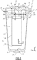
- This filter 10 comprises a cup 12, defining a reception volume V12, and a filter element 14 housed in the reception volume V12.
- the filter element 14 is a filter cartridge of rigid or partially rigid cylindrical shape.
- the filter element 14 comprises, for example, a rigid disc-shaped bottom 14A and a frame not shown, while a canvas 14B of the cylindrical cartridge is made of a flexible and porous material.
- the material of the fabric 14B can be natural or synthetic, depending on the nature of the liquid product to be filtered. It can, for example, be stainless steel, polymer or cellulose.
- the cup 12 is made of a material which takes into account the nature of the liquid product which must pass through the filter element.
- the cup is made of metal, preferably stainless steel. It has, for example, a fixed capacity of between one and two liters.
- the filter 10 further comprises a valve 20 integrated in a head 22.
- the cup is reversibly assembled with the head 22.
- the components 12 and 22 can be screwed together, snapped or assembled by a bayonet-type mechanism or with flanges.
- the filter element is, for its part, removably attached to the lower face 221 of the head 22, and is held by a mechanical fastening system, for example screw, clip, etc.
- the bucket 12 is in symmetry of revolution about a longitudinal axis L12 of the cup 12.
- the filter element 14 is in symmetry of revolution about a longitudinal axis L14 of this element.
- the longitudinal axes L12 and L14 are coincident and parallel to the Z axis.
- the longitudinal axes L12 and L14 are included in the section plane III of the figure 2 .
- the longitudinal axis L12 of the cup 12 and the longitudinal axis L14 of the filter element 14 are not the same.
- the cup 12 comprises a bottom 13 pierced with a purge orifice 31, preferably coaxial with the longitudinal axis L12.
- a purge orifice 31 is closed by a plug 32 or the like.
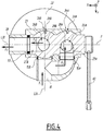
- the filter 10 further comprises a pipe 16 for admission of liquid product intended to be connected to the portion 54 and a pipe 18 for discharging liquid product intended to be connected to the portion 56.
- the pipes 16 and 18 have cylindrical sections and the longitudinal axes L16 and L18 of the pipes 16 and 18 are respectively parallel to the Y and X axes of the orthonormal frame.
- the longitudinal axes L16 and L18 of the pipes 16 and 18 are included in the section plane IV of the figure 2 .
- the valve 20 comprises at least one ball valve.
- the valve 20 is movable in rotation, by causing the ball to pivot about a pivot axis P parallel to the axis X, the pivot axis P corresponding to the intersection between the planes III and IV of the figure 2 .
- the pivot axis P is defined by the body 23 of the valve 20 which, in practice, consists of a part of the head 22.
- the valve 20 comprises two ball valves 24A and 24B integral with one another.
- the bushels 24A and 24B are formed by a single piece.
- Each ball 24A and 24B is a part with a spherical outer casing, partially hollowed out, such as a ball pierced by a duct 26A or 26B opening into two separate orifices specific to each valve 24A or 24B.
- the conduits 26A and 26B are bent, each preferably forming an angle of 90 °, and have circular sections of diameters substantially equal to those of the pipes 16 and 18.
- the diameters of the conduits 26A and 26B are smaller than those of the pipes 16 and 18.
- the bent conduits 26A and 26B each respectively comprise two rectilinear portions 25A, 27A and 25B, 27B and a respective right angle bend 28A and 28B.
- first plug 24A is crossed by the conduit 26A, formed by the rectilinear portions 25A and 27A connected to each other by the elbow 28A.
- second plug 24B is crossed by the duct 26B, formed by the rectilinear portions 25B and 27B connected to each other by the elbow 28B.
- the body 23 defines a housing accommodating the plugs 24A and 24B of the valve 20.
- the housing is formed of two spherical cavities 23A and 23B which open into one another and each respectively receive a ball valve 24A or 24B.
- the pipes 16 and 18 are formed by the body 23 of the head 22.
- the cavity 23A accommodating the first ball valve 24A is fluidly connected to the intake pipe 16 while the cavity 23B accommodating the second ball valve 24B is fluidly connected to the discharge tubing 18.
- the filter 10 also includes at least one air inlet port.
- the filter 10 here comprises two air inlet orifices 36A and 36 B, formed in a wall 232 of the body 23, this wall being parallel to the plane formed by the axes X and Z.
- the orifices 36A and 36B open out. respectively in the cavities 23A and 23B, each facing a ball valve 24A or 24B.
- the number of air inlet openings and / or their location may be different, provided that they fulfill their function, described below.
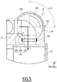
- At least one of the ball valves 24A or 24B is provided with a groove 34A or 34B for placing the receiving volume V12 in communication with the air inlet port 36, which is adjacent thereto, when the valve 20 is in its second position, as visible at the figure 8 .
- each plug 24A and 24B includes its own groove, the groove 34A of the plug 24A being visible at figures 5 and 8 , while the two grooves 34A and 34B are visible at the figure 6 .
- the grooves 34A and 34B hollow out to a small depth the surfaces of the plugs 24A and 24B, so as not to open into the conduits 26A and 26B.
- the two grooves 34 are identical or almost identical to one another.
- each groove 34A and 34 B extends over 90 ° on the surface of the plug 24A or 24B on which it is formed on which it is formed.
- Seals 51A and 51B are arranged in the body 23 at the level of the junctions between the intake manifold 16 and the ball valves 24A and 24B.
- a seal 53 is disposed in the body 23, at the level of the junction between the discharge pipe 18 and the ball valve 24B.
- Seals 55A and 55B are arranged in the body 23 at the level of the junctions between the volume V12 and the plugs 24A and 24B.
- the joints 51A, 51B, 55A and 55B have a geometry adapted to the spherical profile of the plugs 24A and 24B.
- the seals are integral with the body 23 of the head 22; they are therefore not rotated during the pivoting of the plugs 24A and 24B.
- a manual control member formed here by a lever 40, is integral, in rotation about the pivot axis P, of the first valve 24A and makes it possible to actuate the valve 20.
- the valve 20 is configured to selectively take two distinct positions.
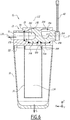
- valve 20 In its first position represented in figures 1 to 5 , the valve 20 connects the intake manifold 16 to the receiving volume V12, through the elbow duct 26A, and this receiving volume V12 to the discharge pipe 18, through the elbow duct 26B. In its second position shown in figures 6 to 8 , the valve 20 directly connects the intake pipe 16 to the discharge pipe 18, through the bent pipe 26B. The second position of the valve 20 makes it possible to isolate the receiving volume V12 from the two pipes 16 and 18. Thus, when the valve 20 is in its second position, the liquid product circulates between the inlet pipe 16 and the pipe d. 'discharge 18 without passing either into the cup 12 or through the filter element 14, this configuration corresponds to the "bypass".
- the arrows F1 and F2 here respectively indicate the directions and the direction of the flow entering the filter 10 through the intake pipe 16 and leaving through the discharge pipe 18.
- a rotation of amplitude equal to 90 ° carried out by manual actuation of the handle 40, allows the valve 20 to switch from its first position to its second position, and vice versa. Since the ball valves 24A and 24B are integral with one another, they are simultaneously pivoted about the pivot axis P when the lever 40 is actuated.
- the straight portion 25A In the first position of the valve 20, the straight portion 25A is parallel to the Y axis and connected with the intake manifold 16, the straight portion 27A is parallel to the Z axis, thus allowing the liquid product to flow. flow into volume V12 of cup 12, following a path represented by arrows F1 and F3 on the figures 3 to 5 .
- the product then passes through the filter element 14, as represented by the arrow F4 on the figure 3 , then passes through the second valve 24B following the arrow F5 before being discharged through the orifice 18 following the arrow F2.
- the straight portion 25B is then parallel to the Z axis and the straight portion 27B is parallel to the X axis and connected with the discharge pipe 18.
- the straight portion 27A is parallel to the Y axis and connected with the intake manifold 16
- the straight portion 25A is parallel to the Z axis and disposed opposite a wall 234 formed by the body 23, on the side of the head 22 opposite the cup 12.
- the liquid product is forced to pass directly through the conduit 26B of the second valve 24B, by following the arrows F1 and F2 visible in particular on the figure 7 .
- the straight portion 25B is here parallel to the Y axis and connected with the intake manifold 16, the straight portion 27B is here parallel to the X axis and connected with the discharge pipe 18.
- the straight portion 27B is constantly parallel to the axis X.
- the position of the handle 40 indicates the degree of opening or closing of the internal plug (s) 24A and 24B at the head 22.
- the valve 20 When the handle is oriented along the Y axis, therefore parallel to the axis L16, the valve 20 is in its first position, the liquid product then passes through pipe 26A, into cup 12 and through filter element 14, before being discharged through orifice 18 through pipe 26B of the second valve 24B.
- the lever 40 When the lever 40 is oriented parallel to the Z axis, therefore perpendicular to the axis L16, the valve 20 is in its second position, the liquid product circulates in the bypass formed by the bent pipe 26B.
- the grooves 34A and 34B create a passage between the air inlet openings 36A and 36B and the receiving volume V12, then making it possible to put the inside of the cup 12 at atmospheric pressure and to perform a purge. of the filter 10 through the drain hole 31 of the bottom 13, after having removed the plug 32, which is represented by the arrow F6 at the figure 6 .
- the valve 20 After having closed the orifice 31 with the button 32, the valve 20 is moved back to its first position, which makes the filter 10 operational again. So the change of filter element 14 can take place quickly and easily, without major disruption of the operation of the installation 1.
- conduits 26A and 26B are used in the two positions of the valve 20, they are permanently wetted by the liquid product. There is therefore no risk of deposits forming in these conduits, unlike a bypass pipe used occasionally. The filter change operation therefore takes place without revealing any retention zone where the product would not be renewed and where it could deteriorate.
- the inlet pipe of the filter 10 may be the pipe 18, while the discharge pipe is the pipe 16. This is for example the case of so-called "pocket” filters. .
- the direction of arrows F1 to F5 is then reversed; the arrows F1 and F2 are swapped, as are the arrows F3 and F5.
- the invention is not limited to the case where the liquid product is a coating product.
- the filter 10 can be used in particular to filter an oil, for example for an engine, a cleaning product, water leaving a well, or a more viscous product such as glue, paste, sealant, anti-gravel or soundproofing.
- valve 20 is motorized, in particular in order to be remotely controlled or robotized, which makes it possible to actuate the valve remotely.
- the plugs 24A and 24B are cylindrical plugs.
- the valve 20 comprises a single cylindrical or spherical valve, which is then advantageously multi-channel.
Description
La présente invention concerne un filtre pour produit liquide ou visqueux. Ce filtre comprend un élément filtrant et un godet définissant un volume de réception accueillant l'élément filtrant, ainsi qu'une tubulure d'admission et une tubulure d'évacuation de produit liquide ou visqueux.The present invention relates to a filter for liquid or viscous product. This filter comprises a filter element and a cup defining a receiving volume accommodating the filter element, as well as an inlet pipe and an outlet pipe for liquid or viscous product.
Dans le domaine des installations comportant des circuits de distribution de produits liquide ou visqueux comprenant des filtres, un circuit de dérivation peut être mis en place afin d'assurer la continuité de service d'une installation lors d'un changement d'élément de filtrant. Plusieurs méthodes de changement d'élément filtrant sont connues ; chaque méthode comporte des avantages et des inconvénients. Les inconvénients majeurs sont notamment le prix élevé, par exemple dans le cas d'un circuit de dérivation utilisant deux corps de filtre et quatre vannes, ou le risque de pollution, par exemple dans le cas d'un circuit de dérivation sans corps de filtre, utilisant un simple tuyau où le produit liquide ou visqueux peut se détériorer entre deux utilisations.In the field of installations comprising distribution circuits for liquid or viscous products comprising filters, a bypass circuit can be set up in order to ensure the continuity of service of an installation when a filter element is changed. . Several methods of changing the filter element are known; each method has advantages and disadvantages. The major drawbacks are in particular the high price, for example in the case of a bypass circuit using two filter bodies and four valves, or the risk of pollution, for example in the case of a bypass circuit without a filter body. , using a simple hose where the liquid or viscous product can deteriorate between two uses.
Il est connu de
Les documents
C'est à ces problèmes qu'entend plus particulièrement remédier l'invention, en proposant un nouveau filtre plus économique et plus simple à manipuler.It is these problems that the invention more particularly intends to remedy, by proposing a new filter that is more economical and easier to handle.
A cet effet, l'invention concerne un filtre du type précité selon la revendication 1.To this end, the invention relates to a filter of the aforementioned type according to claim 1.
Grâce à l'invention, le changement d'élément filtrant est simple et économique. Le filtre fait intervenir un nombre de pièces limité, ce qui facilite les manipulations de changement d'élément filtrant en plus d'être avantageux économiquement. La vanne est en mesure de basculer d'une position à l'autre, modifiant ainsi le trajet parcouru par le produit liquide ou visqueux. Le produit liquide ou visqueux est filtré par l'élément filtrant à l'intérieur du godet lorsque la vanne est dans sa première position. La deuxième position de la vanne sert à créer un circuit de dérivation, couramment appelé « by-pass », permettant d'isoler le volume de réception vis-à-vis des tubulures, sans créer des zones de rétention trop nombreuses ou trop volumineuses, ce qui permet de démonter le godet et d'accéder à l'élément filtrant pour procéder à son remplacement, sans arrêter l'installation. La continuité de service est ainsi assurée.Thanks to the invention, the change of filter element is simple and economical. The filter involves a limited number of parts, which facilitates the handling of changing the filter element in addition to being economically advantageous. The valve is able to switch from one position to another, thus modifying the path traveled by the liquid or viscous product. Liquid or viscous product is filtered by the filter element inside the cup when the valve is in its first position. The second position of the valve is used to create a bypass circuit, commonly called a "bypass", allowing the reception volume to be isolated from the pipes, without creating too many or too large retention areas, which makes it possible to dismantle the bucket and access the filtering element to proceed with its replacement, without stopping the installation. Continuity of service is thus ensured.
Selon des aspects avantageux mais non obligatoires de l'invention, un tel filtre peut incorporer une ou plusieurs des caractéristiques suivantes, prises selon toute combinaison techniquement admissible :
- Le filtre comprend au moins un orifice d'entrée d'air et un orifice de purge.
- Au moins un boisseau sphérique comporte une rainure pour mettre en communication le volume de réception avec l'un orifice d'entrée d'air lorsque la vanne est dans sa deuxième position.
- Le filtre comprend un organe de commande manuelle de la position de la vanne.
- La vanne est mobile entre sa première position et sa deuxième position, et réciproquement, par une rotation, dont l'amplitude est de préférence égale à 90°, autour d'un axe de pivotement défini par un corps de la vanne.
- La vanne est intégrée dans une tête montée de façon amovible sur le godet.
- L'élément filtrant est une cartouche de forme cylindrique montée de façon amovible sur la tête.
- The filter includes at least an air inlet port and a purge port.
- At least one ball valve has a groove for communicating the receiving volume with the one air inlet port when the valve is in its second position.
- The filter comprises a device for manual control of the position of the valve.
- The valve is movable between its first position and its second position, and vice versa, by a rotation, the amplitude of which is preferably equal to 90 °, around a pivot axis defined by a body of the valve.
- The valve is integrated in a head removably mounted on the bucket.
- The filter element is a cylindrically shaped cartridge removably mounted on the head.
L'invention a également pour objet une installation de pulvérisation comprenant un réservoir de produit liquide ou visqueux, une pompe et un pulvérisateur, ainsi qu'un filtre pour produit liquide ou visqueux tel que décrit précédemment.The subject of the invention is also a spraying installation comprising a reservoir for liquid or viscous product, a pump and a sprayer, as well as a filter for liquid or viscous product as described above.
L'invention sera mieux comprise et d'autres avantages de celle-ci apparaîtront plus clairement à la lumière de la description qui va suivre, d'un mode de réalisation d'un filtre et d'une installation de pulvérisation conformes à son principe, donnée uniquement à titre d'exemple et faite en référence aux dessins annexés dans lesquels :
- [
Fig 1 ] lafigure 1 est un schéma représentant un exemple d'installation dans un circuit de circulation de peinture connu sous le nom de « circulating » de peinture qui alimente au moins un poste de pulvérisation pour produit liquide conforme à l'invention ; - [
Fig 2 ] lafigure 2 est une vue en perspective d'un filtre de l'installation de lafigure 1 , une vanne de ce filtre étant dans une première position ; - [
Fig 3 ] lafigure 3 est une coupe du filtre à plus grande échelle, suivant le plan III de lafigure 2 ; - [
Fig 4 ] lafigure 4 est une coupe du filtre à la même échelle que lafigure 3 , suivant le plan IV de lafigure 2 ; - [
Fig 5 ] lafigure 5 est une coupe d'une partie supérieure du filtre suivant le plan V de lafigure 2 ; - [
Fig 6 ] lafigure 6 est une coupe du filtre analogue à lafigure 3 , également suivant le plan III, lorsque la vanne est dans une deuxième position ; - [
Fig 7 ] lafigure 7 est une coupe du filtre analogue à lafigure 4 , également suivant le plan IV, lorsque la vanne est dans la deuxième position ; et - [
Fig 8 ] lafigure 8 est une coupe partielle du filtre analogue à lafigure 5 , également suivant le plan V, lorsque la vanne est dans la deuxième position.
- [
Fig 1 ] thefigure 1 is a diagram showing an example of installation in a paint circulation circuit known under the name of paint “circulating” which supplies at least one spraying station for liquid product in accordance with the invention; - [
Fig 2 ] thefigure 2 is a perspective view of a filter of the installation of thefigure 1 , a valve of this filter being in a first position; - [
Fig 3 ] thefigure 3 is a cross-section of the filter on a larger scale, following plane III of thefigure 2 ; - [
Fig 4 ] thefigure 4 is a cross section of the filter at the same scale as thefigure 3 , according to plan IV of thefigure 2 ; - [
Fig 5 ] thefigure 5 is a section of an upper part of the filter along the plane V of thefigure 2 ; - [
Fig 6 ] thefigure 6 is a cross section of the filter similar to thefigure 3 , also according to plan III, when the valve is in a second position; - [
Fig 7 ] thefigure 7 is a cross section of the filter similar to thefigure 4 , also according to plan IV, when the valve is in the second position; and - [
Fig 8 ] thefigure 8 is a partial section of the filter similar to thefigure 5 , also along the V plane, when the valve is in the second position.
Pour faciliter la navigation d'une figure à l'autre, un repère orthonormé X-Y-Z est représenté sur les
Sur la
Le produit liquide est par exemple un produit de revêtement, tel que de la peinture ou du vernis.The liquid product is for example a coating product, such as paint or varnish.
Le pulvérisateur 6 peut être de type pneumatique ou « airless », électrostatique ou non. Il peut s'agir d'un pistolet manuel, comme représenté à la
L'installation 1 comprend de plus un filtre 10 pour produit liquide, tel que décrit par la suite. Ce filtre est intercalé, dans l'ensemble de tuyaux 5, entre le réservoir 2 et un piquage 52 de cet ensemble 5 dédié à l'alimentation du pulvérisateur 6.The installation 1 further comprises a
Ici, le filtre 10 est en aval de la pompe 4. Il peut toutefois être disposé en amont de celle-ci.Here, the
On note 54 la portion de l'ensemble de tuyaux 5 située immédiatement en amont du filtre 10. On note 56 la portion de cet ensemble située immédiatement en aval de ce filtre. Le filtre 10 est intercalé entre les portions 54 et 56 de l'ensemble de tuyaux 5.54 denotes the portion of the assembly of
Le filtre 10 est représenté seul aux
Le godet 12 est réalisé dans un matériau qui tient compte de la nature du produit liquide qui doit traverser l'élément filtrant. Dans l'exemple des figures, où il s'agit d'un produit de revêtement, le godet est en métal, préférentiellement en inox. Il présente, par exemple, une capacité fixe comprise entre un et deux litres.The
Le filtre 10 comprend de plus une vanne 20 intégrée dans une tête 22.The
Le godet est assemblé de façon réversible avec la tête 22. Par exemple, les composants 12 et 22 peuvent être vissés ensemble, encliquetés ou assemblés par un mécanisme de type baïonnette ou avec des brides.The cup is reversibly assembled with the
L'élément filtrant est, quant à lui, rapporté de façon amovible sur la face inférieure 221 de la tête 22, et est maintenu par un système de fixation mécanique, par exemple à vis, clip, etc..The filter element is, for its part, removably attached to the
Le godet 12 est à symétrie de révolution autour d'un axe longitudinal L12 du godet 12. L'élément filtrant 14 est à symétrie de révolution autour d'un axe longitudinal L14 de cet élément. Sur les
En variante, l'axe longitudinal L12 du godet 12 et l'axe longitudinal L14 de l'élément filtrant 14 ne sont pas confondus.As a variant, the longitudinal axis L12 of the
Le godet 12 comprend un fond 13 percé d'un orifice de purge 31, préférentiellement coaxial avec l'axe longitudinal L12. Lorsque l'élément filtrant 14 est utilisé pour filtrer le produit liquide, l'orifice 31 est obturé par un bouchon 32 ou un autre élément d'obturation similaire.The
Le filtre 10 comprend en outre une tubulure 16 d'admission de produit liquide destinée à être raccordée à la portion 54 et une tubulure 18 d'évacuation de produit liquide destinée à être raccordée à la portion 56. Comme visible à la
La vanne 20 comporte au moins un boisseau sphérique. La vanne 20 est mobile en rotation, en faisant pivoter le boisseau sphérique autour d'un axe de pivotement P parallèle à l'axe X, l'axe de pivotement P correspondant à l'intersection entre les plans III et IV de la
Dans l'exemple, les axes L18 et P sont confondus. Ceci n'est toutefois pas obligatoire.In the example, the axes L18 and P are merged. However, this is not compulsory.
Dans le mode de réalisation de l'invention représenté sur les figures et décrit par la suite, la vanne 20 comporte deux boisseaux sphériques 24A et 24B solidaires entre eux. Ici, les boisseaux 24A et 24B sont formés par une pièce monobloc. Chaque boisseau sphérique 24A et 24B est une pièce à enveloppe externe sphérique, partiellement évidée, telle une boule percée par un conduit 26A ou 26B débouchant dans deux orifices distincts et propres à chaque boisseau 24A ou 24B. Les conduits 26A et 26B sont coudés, formant préférentiellement chacun un angle de 90°, et ont des sections circulaires de diamètres sensiblement égaux à ceux des tubulures 16 et 18.In the embodiment of the invention shown in the figures and described below, the
En variante, les diamètres des conduits 26A et 26B sont inférieurs à ceux des tubulures 16 et 18.As a variant, the diameters of the
En pratique, les conduits coudés 26A et 26B comprennent chacun respectivement deux portions rectilignes 25A, 27A et 25B, 27B et un coude à angle droit respectif 28A et 28B. Ainsi le premier boisseau 24A est traversé par le conduit 26A, formés par les portions rectilignes 25A et 27A reliées entre elles par le coude 28A. En outre, le deuxième boisseau 24B est traversé par le conduit 26B, formés par les portions rectilignes 25B et 27B reliées entre elles par le coude 28B.In practice, the
Le corps 23 délimite un logement accueillant les boisseaux 24A et 24B de la vanne 20. Le logement est formé de deux cavités sphériques 23A et 23B qui débouchent l'une dans l'autre et accueillant chacune respectivement un boisseau sphérique 24A ou 24B. Les tubulures 16 et 18 sont formées par le corps 23 de la tête 22. La cavité 23A accueillant le premier boisseau sphérique 24A est raccordé fluidiquement à la tubulure d'admission 16 tandis que la cavité 23B accueillant le deuxième boisseau sphérique 24B est raccordée fluidiquement à la tubulure d'évacuation 18.The
Le filtre 10 comprend également au moins un orifice d'entrée d'air. En pratique, le filtre 10 comprend ici deux orifices d'entrée d'air 36A et 36 B, ménagés dans une paroi 232 du corps 23, cette paroi étant parallèle au plan formé par les axes X et Z. Les orifices 36A et 36B débouchent respectivement dans les cavités 23A et 23B, chacune en regard d'un boisseau sphérique 24A ou 24B.The
En variante, le nombre d'orifices d'entrée d'air et/ou leur emplacement peuvent être différent, à condition qu'ils remplissent leur fonction, décrite ci-après.As a variant, the number of air inlet openings and / or their location may be different, provided that they fulfill their function, described below.
Au moins l'un des boisseaux sphériques 24A ou 24B est pourvu d'une rainure 34A ou 34B pour mettre en communication le volume de réception V12 avec l'orifice d'entrée d'air 36, qui lui est adjacent, lorsque la vanne 20 est dans sa deuxième position, comme visible à la
Des joints d'étanchéité 51A et 51B sont disposés dans le corps 23 au niveau des jonctions entre la tubulure d'admission 16 et les boisseaux sphériques 24A et 24B. Un joint d'étanchéité 53 est disposé dans le corps 23, au niveau de la jonction entre la tubulure d'évacuation 18 et le boisseau sphérique 24B. Des joints d'étanchéité 55A et 55B sont disposés dans le corps 23 au niveau des jonctions entre le volume V12 et les boisseaux 24A et 24B. Les joints 51A, 51B, 55A et 55B ont une géométrie adaptée au profil sphérique des boisseaux 24A et 24B.
Les joints d'étanchéité sont solidaires du corps 23 de la tête 22 ; ils ne sont donc pas entrainés en rotation lors du pivotement des boisseaux 24A et 24B.The seals are integral with the
Un organe de commande manuelle, formé ici par une manette 40, est solidaire, en rotation autour de l'axe de pivotement P, du premier boisseau 24A et permet d'actionner la vanne 20.A manual control member, formed here by a
La vanne 20 est configurée pour prendre sélectivement deux positions distinctes.The
Dans sa première position représentée aux
Les flèches F1 et F2 indiquent ici respectivement les directions et le sens du flux entrant dans le filtre 10 par la tubulure d'admission 16 et en sortant par la tubulure d'évacuation 18.The arrows F1 and F2 here respectively indicate the directions and the direction of the flow entering the
En pratique, une rotation d'amplitude égale à 90°, réalisée par un actionnement manuel de la manette 40, permet à la vanne 20 de basculer de sa première position à sa deuxième position, et réciproquement. Les boisseaux sphériques 24A et 24B étant solidaires entre eux, ils sont pivotés simultanément autour de l'axe de pivotement P lorsque la manette 40 est actionnée.In practice, a rotation of amplitude equal to 90 °, carried out by manual actuation of the
Dans la première position de la vanne 20, la portion droite 25A est parallèle à l'axe Y et reliée avec la tubulure d'admission 16, la portion droite 27A est parallèle à l'axe Z, permettant ainsi au produit liquide de s'écouler jusque dans le volume V12 du godet 12, en suivant un trajet représenté par les flèches F1 et F3 sur les
Dans la deuxième position de la vanne, la portion droite 27A est parallèle à l'axe Y et reliée avec la tubulure d'admission 16, la portion droite 25A est parallèle à l'axe Z et disposée en regard d'une paroi 234 formée par le corps 23, sur le côté de la tête 22 opposée au godet 12. Le produit liquide qui se trouve dans le conduit 26A du premier boisseau 24A se heurte à la paroi 234, le conduit 26A forme donc un brin mort, comme visible sur la
On note que dans les deux positions de la vanne 20, la portion droite 27B est constamment parallèle à l'axe X.It is noted that in the two positions of the
Avantageusement, la position de la manette 40 indique le degré d'ouverture ou de fermeture du ou des boisseaux interne 24A et 24B à la tête 22. Lorsque la manette est orientée selon l'axe Y, donc parallèle à l'axe L16, la vanne 20 est dans sa première position, le produit liquide passe alors par le conduit 26A, dans le godet 12 et par l'élément filtrant 14, avant d'être évacué par l'orifice 18 par l'intermédiaire du conduit 26B du deuxième boisseau 24B. Lorsque la manette 40 est orientée parallèlement à l'axe Z, donc perpendiculaire à l'axe L16, la vanne 20 est dans sa deuxième position, le produit liquide circule dans le by-pass formé par le conduit coudé 26B.Advantageously, the position of the
Dans cette position, les rainures 34A et 34B créent un passage entre les orifices d'entrée d'air 36A et 36B et le volume de réception V12, permettant alors de mettre l'intérieur du godet 12 à pression atmosphérique et de procéder à une purge du filtre 10 à travers l'orifice de purge 31 du fond 13, après avoir retiré le bouchon 32, ce que représente la flèche F6 à la
Une fois le godet 12 purgé à travers l'orifice 31 et alors que la vanne 20 demeure dans sa deuxième position, il est possible de désolidariser le godet 12 de la tête 22, en désactivant les moyens de montage réversible qui les assemblent. On peut alors retirer le godet 22 de sous la tête 22 et accéder à l'élément filtrant 14 qui demeure monté sous la tête 12, de façon amovible.Once the
Il est alors possible de retirer l'élément filtrant 14 de la tête 22 et de procéder à son remplacement, au moyen d'un nouvel élément filtrant. Le godet 12 peut alors être remonté sur la tête 12, autour du nouvel élément filtrant.It is then possible to remove the
Après avoir rebouché l'orifice 31 avec le bouton 32, on rebascule la vanne 20 dans sa première position, ce qui rend le filtre 10 à nouveau opérationnel. Ainsi, le changement d'élément filtrant 14 peut avoir lieu rapidement et simplement, sans perturbation majeure du fonctionnement de l'installation 1.After having closed the
Comme les conduits 26A et 26B sont utilisées dans les deux positions de la vanne 20, ils sont en permanence mouillés par le produit liquide. Il n'y a donc pas de risque que des dépôts se forment dans ces conduits, à la différence d'un tuyau de by-pass utilisé occasionnellement. L'opération de changement de filtre se déroule donc sans faire apparaitre aucune zone de rétention où le produit ne serait pas renouvelé et où il pourrait se détériorer.As the
Selon une variante non représentée de l'invention, la tubulure d'admission du filtre 10 peut être la tubulure 18, alors que la tubulure d'évacuation est la tubulure 16. C'est par exemple le cas des filtres dits « à poche ». Le sens des flèches F1 à F5 est alors inversé ; les flèches F1 et F2 sont permutées, de même que les flèches F3 et F5.According to a variant not shown of the invention, the inlet pipe of the
L'invention n'est pas limitée au cas où le produit liquide est un produit de revêtement. Le filtre 10 peut être utilisé notamment pour filtrer une huile, par exemple pour un moteur, un produit de nettoyage, de l'eau en sortie d'un puits, ou un produit plus visqueux de type colle, pâte, mastic d'étanchéité, anti-gravillon ou insonorisant.The invention is not limited to the case where the liquid product is a coating product. The
Alternativement, la vanne 20 est motorisée, notamment afin d'être télécommandée ou robotisée, ce qui permet d'actionner la vanne à distance.Alternatively, the
En variante, les boisseaux 24A et 24B sont des boisseaux cylindriques.Alternatively, the
Selon une variante non représentée de l'invention, la vanne 20 comporte un seul boisseau cylindrique ou sphérique, lequel est alors avantageusement multicanaux.According to a variant of the invention that is not shown, the
Toute caractéristique de l'un des modes de réalisation ou variante décrite cidessus, peut être mise en oeuvre dans les autres modes de réalisation et variantes décrits.Any characteristic of one of the embodiments or variant described above can be implemented in the other embodiments and variants described.
Claims (8)
- A filter (10) for a liquid or viscous product, this filter comprising a filtering element (14) and a bucket (12) defining a receiving volume (V12) accommodating the filtering element, the filter (10) comprising a liquid or viscous product intake tubing (16) and a liquid or viscous product discharge tubing (18), the filter (10) comprising a valve (20) configured to assume:a first position where the valve (20) couples the intake tubing (16) to the receiving volume (V12) and this receiving volume (V12) to the discharge tubing (18); anda second position where the valve (20) couples the intake tubing (16) to the discharge tubing (18) and isolates the receiving volume (V12) relative to the two tubings (16, 18)characterized in that the valve (20) includes two cylindrical or spherical sliding gates (24A, 24B), including a first cylindrical or spherical sliding gate (24A) including a first duct (26A) which couples the intake tubing (16) to the receiving volume (V12), when the valve (20) is in its first position, and which forms a dead line, when the valve (20) is in its second position, and a second cylindrical or spherical sliding gate (24B) including a second duct (26B) which couples the receiving volume (V12) to the discharge tubing (18), when the valve is (20) in its second position, and which couples the intake tubing (16) to the discharge tubing (18), when the valve (20) is in its second position.
- The filter according to the preceding claim, characterized in that the filter (10) comprises at least one air intake orifice (36A, 36B) and one purge orifice (31).
- The filter according to claim 2, characterized in that at least one spherical sliding gate (24A, 24B) includes a slot (34A, 34B) for placing the receiving volume (V12) in communication with the one air intake orifice (36A, 36B) when the valve (20) is in its second position.
- The filter according to any one of the preceding claims, characterized in that it comprises a member (40) for manually controlling the position of the valve (20).
- The filter according to any one of the preceding claims, characterized in that the valve (20) is movable between its first position and its second position, and reciprocally, by a rotation, the amplitude of which is preferably equal to 90°, around a pivot axis (P) defined by a body (23) of the valve.
- The filter according to any one of the preceding claims, characterized in that the valve (20) is integrated into a head (22) mounted removably on the bucket (12).
- The filter according to the preceding claim, characterized in that the filtering element (14) is a cylindrical cartridge mounted removably on the head (22).
- A spraying installation comprising a tank (2) of liquid or viscous product, a pump (4) and a sprayer (6), characterized in that the installation (1) comprises a filter (10) for liquid or viscous product according to any one of the preceding claims.
Applications Claiming Priority (1)
| Application Number | Priority Date | Filing Date | Title |
|---|---|---|---|
| FR1900962A FR3092501B1 (en) | 2019-01-31 | 2019-01-31 | Filter for liquid or viscous product and spraying installation comprising such a filter |
Publications (2)
| Publication Number | Publication Date |
|---|---|
| EP3689435A1 EP3689435A1 (en) | 2020-08-05 |
| EP3689435B1 true EP3689435B1 (en) | 2021-10-06 |
Family
ID=66867463
Family Applications (1)
| Application Number | Title | Priority Date | Filing Date |
|---|---|---|---|
| EP20154641.3A Active EP3689435B1 (en) | 2019-01-31 | 2020-01-30 | Filter for a liquid or viscous product and spraying facility comprising such a filter |
Country Status (6)
| Country | Link |
|---|---|
| US (1) | US10974178B2 (en) |
| EP (1) | EP3689435B1 (en) |
| KR (1) | KR20200095407A (en) |
| CN (1) | CN111495003B (en) |
| ES (1) | ES2901894T3 (en) |
| FR (1) | FR3092501B1 (en) |
Family Cites Families (12)
| Publication number | Priority date | Publication date | Assignee | Title |
|---|---|---|---|---|
| US2602697A (en) * | 1949-02-23 | 1952-07-08 | Paul F Otto | Mixer device |
| US2604446A (en) * | 1949-09-19 | 1952-07-22 | Bruner Corp | Water conditioning device |
| US3420375A (en) * | 1966-03-21 | 1969-01-07 | Marvel Eng Co | Filter with automatic bypass-shutoff |
| CA962915A (en) * | 1971-04-05 | 1975-02-18 | Sam Close | Valve for a filter |
| FR2472707A1 (en) * | 1979-12-31 | 1981-07-03 | Ferodo Sa | DEVICE FOR CONTROLLING THE LIQUID SUPPLY OF AN APPARATUS, IN PARTICULAR A HEAT EXCHANGER, ESPECIALLY FOR A MOTOR VEHICLE |
| US5152321A (en) * | 1991-10-07 | 1992-10-06 | Ecowater Systems, Inc. | Bypass valve |
| DK90694A (en) * | 1994-08-03 | 1996-02-04 | Heco International A S | Filters, especially magnetic filters, for continuous operation |
| US5931196A (en) * | 1998-04-29 | 1999-08-03 | United States Filter Corporation | Bypass valve |
| US6746600B2 (en) * | 2001-10-31 | 2004-06-08 | Arvin Technologies, Inc. | Fluid filter with integrated cooler |
| US8888998B2 (en) * | 2010-08-09 | 2014-11-18 | Paragon Water Systems, Inc. | Bypass valve for water filter system |
| MX2015012995A (en) * | 2013-03-15 | 2015-12-01 | Mann & Hummel Purolator Filters Llc | Spherical contact ball joint style spool relief valve. |
| IT201600119549A1 (en) * | 2016-11-25 | 2018-05-25 | Euroacque S R L | DEFANGER FILTER DEVICE |
-
2019
- 2019-01-31 FR FR1900962A patent/FR3092501B1/en not_active Expired - Fee Related
-
2020
- 2020-01-28 US US16/775,124 patent/US10974178B2/en active Active
- 2020-01-30 KR KR1020200010871A patent/KR20200095407A/en unknown
- 2020-01-30 EP EP20154641.3A patent/EP3689435B1/en active Active
- 2020-01-30 ES ES20154641T patent/ES2901894T3/en active Active
- 2020-01-31 CN CN202010077668.1A patent/CN111495003B/en active Active
Also Published As
| Publication number | Publication date |
|---|---|
| KR20200095407A (en) | 2020-08-10 |
| ES2901894T3 (en) | 2022-03-24 |
| CN111495003A (en) | 2020-08-07 |
| CN111495003B (en) | 2023-04-28 |
| US10974178B2 (en) | 2021-04-13 |
| EP3689435A1 (en) | 2020-08-05 |
| US20200246734A1 (en) | 2020-08-06 |
| JP2020124703A (en) | 2020-08-20 |
| FR3092501A1 (en) | 2020-08-14 |
| FR3092501B1 (en) | 2022-08-26 |
Similar Documents
| Publication | Publication Date | Title |
|---|---|---|
| FR2565130A1 (en) | MANUAL SPRAYER AND DIAPHRAGM PUMP FOR SPRAYER | |
| FR2893865A1 (en) | Spray oscillating control apparatus for sprinkler, actuates and rotates linkage gear wheel and covering blocks of spray control device, to switch amount of water supply into inlet orifices provided in water duct of control assembly | |
| FR2536458A1 (en) | INTERNAL COMBUSTION ENGINE WITH SIMPLIFIED LUBRICATION MEANS | |
| EP3689435B1 (en) | Filter for a liquid or viscous product and spraying facility comprising such a filter | |
| EP3724473B1 (en) | Portion of a fluid drainage conduit for a turbomachine | |
| EP3785802B1 (en) | Valve, system for applying a coating product comprising such a valve and dedicated installation and removal tool | |
| FR2893379A1 (en) | COAXIAL INTERCEPTION VALVE FOR USE IN COMPRESSED AIR FACILITIES | |
| WO1987007352A1 (en) | Liquid distribution valve | |
| CA3049216A1 (en) | Energy production assembly and associated process for draining water contained in an aircraft fuel tank | |
| EP1737315A2 (en) | Material dispensing device with a rotary seal | |
| EP2532405B1 (en) | Fuel filter with water drain and filter element for such a filter | |
| EP3177571B1 (en) | Large-capacity water treatment device | |
| WO2008129223A2 (en) | Unitary tap containing a spherical bearing stopper | |
| EP3715996B1 (en) | Mixing unit and mixer tap comprising such a mixing unit | |
| FR3105938A1 (en) | Valve, coating product application system comprising such a valve and dedicated assembly and disassembly tool | |
| CA3049218A1 (en) | System and necessary tank draining and associated draining and assembly processes | |
| FR2977805A1 (en) | Lubricant filtering unit for automatic gear box of motor vehicle, has recirculation duct whose portion has channel-shaped section, and closure plate fixed in single-piece molded shell, where section and plate form tubular section of duct | |
| FR2670270A1 (en) | Single-piece bleed station with built-in isolating valves | |
| EP3321235B1 (en) | Injection cartridge, in particular for a treatment apparatus | |
| FR2843052A1 (en) | PAINT CLEANING INSTALLATION | |
| FR2560695A1 (en) | PRESSURE REGULATOR, IN PARTICULAR FOR A SPRAYING PLANT OF A TREATMENT LIQUID | |
| EP3393965B1 (en) | Equipment comprising an insertable coaxial valve for transferring a fluid into a reservoir, and method | |
| FR2546414A1 (en) | CARTRIDGE FILTER, AS WELL AS A FILTRATION SYSTEM INCLUDING SUCH A FILTER | |
| CA1316792C (en) | Automatic coupling device for piping | |
| EP2253203A1 (en) | Drinking trough for livestock with improved coupling device |
Legal Events
| Date | Code | Title | Description |
|---|---|---|---|
| PUAI | Public reference made under article 153(3) epc to a published international application that has entered the european phase |
Free format text: ORIGINAL CODE: 0009012 |
|
| STAA | Information on the status of an ep patent application or granted ep patent |
Free format text: STATUS: THE APPLICATION HAS BEEN PUBLISHED |
|
| AK | Designated contracting states |
Kind code of ref document: A1 Designated state(s): AL AT BE BG CH CY CZ DE DK EE ES FI FR GB GR HR HU IE IS IT LI LT LU LV MC MK MT NL NO PL PT RO RS SE SI SK SM TR |
|
| AX | Request for extension of the european patent |
Extension state: BA ME |
|
| STAA | Information on the status of an ep patent application or granted ep patent |
Free format text: STATUS: REQUEST FOR EXAMINATION WAS MADE |
|
| 17P | Request for examination filed |
Effective date: 20210111 |
|
| RBV | Designated contracting states (corrected) |
Designated state(s): AL AT BE BG CH CY CZ DE DK EE ES FI FR GB GR HR HU IE IS IT LI LT LU LV MC MK MT NL NO PL PT RO RS SE SI SK SM TR |
|
| GRAP | Despatch of communication of intention to grant a patent |
Free format text: ORIGINAL CODE: EPIDOSNIGR1 |
|
| STAA | Information on the status of an ep patent application or granted ep patent |
Free format text: STATUS: GRANT OF PATENT IS INTENDED |
|
| INTG | Intention to grant announced |
Effective date: 20210511 |
|
| GRAS | Grant fee paid |
Free format text: ORIGINAL CODE: EPIDOSNIGR3 |
|
| GRAA | (expected) grant |
Free format text: ORIGINAL CODE: 0009210 |
|
| STAA | Information on the status of an ep patent application or granted ep patent |
Free format text: STATUS: THE PATENT HAS BEEN GRANTED |
|
| AK | Designated contracting states |
Kind code of ref document: B1 Designated state(s): AL AT BE BG CH CY CZ DE DK EE ES FI FR GB GR HR HU IE IS IT LI LT LU LV MC MK MT NL NO PL PT RO RS SE SI SK SM TR |
|
| REG | Reference to a national code |
Ref country code: GB Ref legal event code: FG4D Free format text: NOT ENGLISH |
|
| REG | Reference to a national code |
Ref country code: CH Ref legal event code: EP Ref country code: AT Ref legal event code: REF Ref document number: 1435733 Country of ref document: AT Kind code of ref document: T Effective date: 20211015 |
|
| REG | Reference to a national code |
Ref country code: DE Ref legal event code: R096 Ref document number: 602020000655 Country of ref document: DE |
|
| REG | Reference to a national code |
Ref country code: IE Ref legal event code: FG4D Free format text: LANGUAGE OF EP DOCUMENT: FRENCH |
|
| REG | Reference to a national code |
Ref country code: LT Ref legal event code: MG9D |
|
| REG | Reference to a national code |
Ref country code: NL Ref legal event code: MP Effective date: 20211006 |
|
| REG | Reference to a national code |
Ref country code: AT Ref legal event code: MK05 Ref document number: 1435733 Country of ref document: AT Kind code of ref document: T Effective date: 20211006 |
|
| REG | Reference to a national code |
Ref country code: ES Ref legal event code: FG2A Ref document number: 2901894 Country of ref document: ES Kind code of ref document: T3 Effective date: 20220324 |
|
| PG25 | Lapsed in a contracting state [announced via postgrant information from national office to epo] |
Ref country code: RS Free format text: LAPSE BECAUSE OF FAILURE TO SUBMIT A TRANSLATION OF THE DESCRIPTION OR TO PAY THE FEE WITHIN THE PRESCRIBED TIME-LIMIT Effective date: 20211006 Ref country code: LT Free format text: LAPSE BECAUSE OF FAILURE TO SUBMIT A TRANSLATION OF THE DESCRIPTION OR TO PAY THE FEE WITHIN THE PRESCRIBED TIME-LIMIT Effective date: 20211006 Ref country code: FI Free format text: LAPSE BECAUSE OF FAILURE TO SUBMIT A TRANSLATION OF THE DESCRIPTION OR TO PAY THE FEE WITHIN THE PRESCRIBED TIME-LIMIT Effective date: 20211006 Ref country code: BG Free format text: LAPSE BECAUSE OF FAILURE TO SUBMIT A TRANSLATION OF THE DESCRIPTION OR TO PAY THE FEE WITHIN THE PRESCRIBED TIME-LIMIT Effective date: 20220106 Ref country code: AT Free format text: LAPSE BECAUSE OF FAILURE TO SUBMIT A TRANSLATION OF THE DESCRIPTION OR TO PAY THE FEE WITHIN THE PRESCRIBED TIME-LIMIT Effective date: 20211006 |
|
| PG25 | Lapsed in a contracting state [announced via postgrant information from national office to epo] |
Ref country code: IS Free format text: LAPSE BECAUSE OF FAILURE TO SUBMIT A TRANSLATION OF THE DESCRIPTION OR TO PAY THE FEE WITHIN THE PRESCRIBED TIME-LIMIT Effective date: 20220206 Ref country code: SE Free format text: LAPSE BECAUSE OF FAILURE TO SUBMIT A TRANSLATION OF THE DESCRIPTION OR TO PAY THE FEE WITHIN THE PRESCRIBED TIME-LIMIT Effective date: 20211006 Ref country code: PT Free format text: LAPSE BECAUSE OF FAILURE TO SUBMIT A TRANSLATION OF THE DESCRIPTION OR TO PAY THE FEE WITHIN THE PRESCRIBED TIME-LIMIT Effective date: 20220207 Ref country code: PL Free format text: LAPSE BECAUSE OF FAILURE TO SUBMIT A TRANSLATION OF THE DESCRIPTION OR TO PAY THE FEE WITHIN THE PRESCRIBED TIME-LIMIT Effective date: 20211006 Ref country code: NO Free format text: LAPSE BECAUSE OF FAILURE TO SUBMIT A TRANSLATION OF THE DESCRIPTION OR TO PAY THE FEE WITHIN THE PRESCRIBED TIME-LIMIT Effective date: 20220106 Ref country code: NL Free format text: LAPSE BECAUSE OF FAILURE TO SUBMIT A TRANSLATION OF THE DESCRIPTION OR TO PAY THE FEE WITHIN THE PRESCRIBED TIME-LIMIT Effective date: 20211006 Ref country code: LV Free format text: LAPSE BECAUSE OF FAILURE TO SUBMIT A TRANSLATION OF THE DESCRIPTION OR TO PAY THE FEE WITHIN THE PRESCRIBED TIME-LIMIT Effective date: 20211006 Ref country code: HR Free format text: LAPSE BECAUSE OF FAILURE TO SUBMIT A TRANSLATION OF THE DESCRIPTION OR TO PAY THE FEE WITHIN THE PRESCRIBED TIME-LIMIT Effective date: 20211006 Ref country code: GR Free format text: LAPSE BECAUSE OF FAILURE TO SUBMIT A TRANSLATION OF THE DESCRIPTION OR TO PAY THE FEE WITHIN THE PRESCRIBED TIME-LIMIT Effective date: 20220107 |
|
| REG | Reference to a national code |
Ref country code: DE Ref legal event code: R097 Ref document number: 602020000655 Country of ref document: DE |
|
| PG25 | Lapsed in a contracting state [announced via postgrant information from national office to epo] |
Ref country code: SM Free format text: LAPSE BECAUSE OF FAILURE TO SUBMIT A TRANSLATION OF THE DESCRIPTION OR TO PAY THE FEE WITHIN THE PRESCRIBED TIME-LIMIT Effective date: 20211006 Ref country code: SK Free format text: LAPSE BECAUSE OF FAILURE TO SUBMIT A TRANSLATION OF THE DESCRIPTION OR TO PAY THE FEE WITHIN THE PRESCRIBED TIME-LIMIT Effective date: 20211006 Ref country code: RO Free format text: LAPSE BECAUSE OF FAILURE TO SUBMIT A TRANSLATION OF THE DESCRIPTION OR TO PAY THE FEE WITHIN THE PRESCRIBED TIME-LIMIT Effective date: 20211006 Ref country code: EE Free format text: LAPSE BECAUSE OF FAILURE TO SUBMIT A TRANSLATION OF THE DESCRIPTION OR TO PAY THE FEE WITHIN THE PRESCRIBED TIME-LIMIT Effective date: 20211006 Ref country code: DK Free format text: LAPSE BECAUSE OF FAILURE TO SUBMIT A TRANSLATION OF THE DESCRIPTION OR TO PAY THE FEE WITHIN THE PRESCRIBED TIME-LIMIT Effective date: 20211006 Ref country code: CZ Free format text: LAPSE BECAUSE OF FAILURE TO SUBMIT A TRANSLATION OF THE DESCRIPTION OR TO PAY THE FEE WITHIN THE PRESCRIBED TIME-LIMIT Effective date: 20211006 |
|
| PLBE | No opposition filed within time limit |
Free format text: ORIGINAL CODE: 0009261 |
|
| STAA | Information on the status of an ep patent application or granted ep patent |
Free format text: STATUS: NO OPPOSITION FILED WITHIN TIME LIMIT |
|
| PG25 | Lapsed in a contracting state [announced via postgrant information from national office to epo] |
Ref country code: MC Free format text: LAPSE BECAUSE OF FAILURE TO SUBMIT A TRANSLATION OF THE DESCRIPTION OR TO PAY THE FEE WITHIN THE PRESCRIBED TIME-LIMIT Effective date: 20211006 |
|
| 26N | No opposition filed |
Effective date: 20220707 |
|
| REG | Reference to a national code |
Ref country code: BE Ref legal event code: MM Effective date: 20220131 |
|
| PG25 | Lapsed in a contracting state [announced via postgrant information from national office to epo] |
Ref country code: LU Free format text: LAPSE BECAUSE OF NON-PAYMENT OF DUE FEES Effective date: 20220130 Ref country code: AL Free format text: LAPSE BECAUSE OF FAILURE TO SUBMIT A TRANSLATION OF THE DESCRIPTION OR TO PAY THE FEE WITHIN THE PRESCRIBED TIME-LIMIT Effective date: 20211006 |
|
| PG25 | Lapsed in a contracting state [announced via postgrant information from national office to epo] |
Ref country code: SI Free format text: LAPSE BECAUSE OF FAILURE TO SUBMIT A TRANSLATION OF THE DESCRIPTION OR TO PAY THE FEE WITHIN THE PRESCRIBED TIME-LIMIT Effective date: 20211006 Ref country code: BE Free format text: LAPSE BECAUSE OF NON-PAYMENT OF DUE FEES Effective date: 20220131 |
|
| PG25 | Lapsed in a contracting state [announced via postgrant information from national office to epo] |
Ref country code: IE Free format text: LAPSE BECAUSE OF NON-PAYMENT OF DUE FEES Effective date: 20220130 |
|
| PGFP | Annual fee paid to national office [announced via postgrant information from national office to epo] |
Ref country code: FR Payment date: 20230125 Year of fee payment: 4 Ref country code: ES Payment date: 20230206 Year of fee payment: 4 Ref country code: CH Payment date: 20230130 Year of fee payment: 4 |
|
| PGFP | Annual fee paid to national office [announced via postgrant information from national office to epo] |
Ref country code: TR Payment date: 20230124 Year of fee payment: 4 Ref country code: IT Payment date: 20230131 Year of fee payment: 4 Ref country code: DE Payment date: 20230112 Year of fee payment: 4 |
|
| PGFP | Annual fee paid to national office [announced via postgrant information from national office to epo] |
Ref country code: ES Payment date: 20240207 Year of fee payment: 5 |