EP0187241A2 - Mécanisme de verrouillage pour cassettes vidéo - Google Patents
Mécanisme de verrouillage pour cassettes vidéo Download PDFInfo
- Publication number
- EP0187241A2 EP0187241A2 EP85114964A EP85114964A EP0187241A2 EP 0187241 A2 EP0187241 A2 EP 0187241A2 EP 85114964 A EP85114964 A EP 85114964A EP 85114964 A EP85114964 A EP 85114964A EP 0187241 A2 EP0187241 A2 EP 0187241A2
- Authority
- EP
- European Patent Office
- Prior art keywords
- post
- arm
- lever
- video cassette
- cassette according
- Prior art date
- Legal status (The legal status is an assumption and is not a legal conclusion. Google has not performed a legal analysis and makes no representation as to the accuracy of the status listed.)
- Granted
Links
- 238000004804 winding Methods 0.000 claims abstract 2
- 230000000284 resting effect Effects 0.000 claims 1
- 239000004033 plastic Substances 0.000 description 7
- 238000005452 bending Methods 0.000 description 2
- 239000000463 material Substances 0.000 description 2
- 230000000694 effects Effects 0.000 description 1
- 238000001746 injection moulding Methods 0.000 description 1
- 238000007689 inspection Methods 0.000 description 1
- 238000009434 installation Methods 0.000 description 1
- 238000004519 manufacturing process Methods 0.000 description 1
- 239000002991 molded plastic Substances 0.000 description 1
- 230000036316 preload Effects 0.000 description 1
- 230000002028 premature Effects 0.000 description 1
- 238000005096 rolling process Methods 0.000 description 1
- 239000000243 solution Substances 0.000 description 1
Images


Classifications
-
- G—PHYSICS
- G11—INFORMATION STORAGE
- G11B—INFORMATION STORAGE BASED ON RELATIVE MOVEMENT BETWEEN RECORD CARRIER AND TRANSDUCER
- G11B23/00—Record carriers not specific to the method of recording or reproducing; Accessories, e.g. containers, specially adapted for co-operation with the recording or reproducing apparatus ; Intermediate mediums; Apparatus or processes specially adapted for their manufacture
- G11B23/02—Containers; Storing means both adapted to cooperate with the recording or reproducing means
- G11B23/04—Magazines; Cassettes for webs or filaments
- G11B23/08—Magazines; Cassettes for webs or filaments for housing webs or filaments having two distinct ends
- G11B23/087—Magazines; Cassettes for webs or filaments for housing webs or filaments having two distinct ends using two different reels or cores
- G11B23/08707—Details
- G11B23/08721—Brakes for tapes or tape reels
Definitions
- the invention relates to a locking mechanism for video cassettes, the pawls in connection with the molded biasing arms have a special geometric shape as a replacement for the wire springs.
- the commercially available video cassettes contain two plane-parallel reels, from which the magnetic tape is wound up or unwound. The tape is pulled out of the cassette to be played on the recorder.
- the cassettes contain locking devices to prevent unintentional loosening of the tape reel when not in use.
- the coil flanges adjacent to the cassette bottom are serrated on their circumference.
- the pivoted pawls themselves consist of two-armed levers, one arm of which rests against a toothed spool when not in use and the second arm of which rests on a release lever.
- the pawls are pretensioned by means of a wire spring for each of the two pawls. One end of the spring engages a lever arm, while the other end is supported on a pin.
- wire springs have an unfavorable effect on the production costs of a video cassette, because the springs require storage, quality inspection, etc.; Installation is also tedious given the narrow interior of a cassette.
- various proposals have already been made to replace the wire springs with molded plastic springs on the pawls. So in DE 27 54 935 curved biasing arms made of plastic, the are molded on the lever arm of the pawl and are supported on the inside of the cassette. The same applies to DE 28 20 866.
- DE 28 37 886 a single resilient plate with a flat and two curved parts is used instead of wire springs. The flat part lies against the side wall of the lower housing part, the curved areas touch the pawls.
- a spring-elastic plastic arm is molded onto the pawls, which is supported against a stationary pin or on the inside of the cassette.
- a single, curved plastic arm is used. The two ends are molded onto the two adjacent lever arms of the pawls, while the curved part presses against the inner wall of the cassette housing.
- this object is achieved in that the deflection point 19a, b of the biasing arm 16a, b, which is fixed to the post 5a, b, is close to the axis of rotation of the pawls.
- the deflection point to the axis of rotation of the pawl has a smaller distance than the radius of the post.
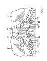
- Fig. 1 shows a partial view of a lower housing part 1 of a conventional video cassette with two reels 2, 3, the lower reel flanges 4a, b of which are serrated.
- the cassette also contains a locking mechanism, each with a pawl 6a, b which can be plugged and pivoted onto a post 5a, b.
- Their lever arm 7a, b also called the first lever arm
- the swiveling range of the first lever arm towards the spool is limited by the enveloping circle 8a, b - a circular depression in the cassette bottom.
- the other lever arm 9a, b (also called the second lever arm) rests on the release component 11 of the release lever 10.
- Wire springs 12a, b, one end of which rests on the first lever arm and the other end of which rests on a pin, are usually used to pretension the locking mechanism.
- the main feature of the invention is not only to replace the wire springs by a leaf spring made of plastic (also called a biasing arm), but to give the totality of the pawls a special geometric shape that minimizes deflection of the biasing arm when Swiveling of the pawls permitted.
- the two lever arms 7a, b and 9a, b are connected by a web 13a, b which runs at right angles to the lever arms.
- the lever arms and the web result in a U-shape.
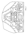
- the distance between the lever arms is selected so that in order to perform their function (FIG. 2) the first lever arm engages in the locked position between the teeth of the lower coil flange and the free end of the second lever arm rests on the release component 11 of the release lever 10.
- their free end is rounded 14a, b.
- the pawl unit is integrally formed on a push-on sleeve 15a, b which is attached to the optionally hollow cylindrical post 5a, b.
- This particular geometric shape of the pawls is chosen in order to create the greatest possible effective spring length for the biasing arm 16a, b.
- the biasing arm is formed on the second lever arm and is so long that its free end 17a, b abuts the post, which is specially designed.
- the post itself can be designed as a bolt or as a sleeve which corresponds in height to that of the first lever arm. In order to be able to serve as a system for the prestressing arm, the free post end is therefore shaped semi-cylindrical 18a, b (FIG. 2).
- One of the two cut surfaces on the hollow cylindrical body is chamfered in such a way that the prestressing arm rests only on its inner edge 19a, b. This is a means of preventing the actuation force applied to the bias arm from pivoting when the pawls are pivoted. If the post end is annular, a slot 20 (Fig. 3) is sufficient to allow the biasing arm to rest.
- One of the two slotted surfaces should also be beveled, as described above. If the height of the post 5 corresponds to that of the push-on sleeve 15 of the pawl, a pin 21 (FIG. 4) arranged eccentrically on the post end can serve as an attachment.
- the second lever arm 9a is generally higher than the first, and can be shaped in an L-shape 22a at its lower end. The pre-tensioning arm adjoins the short leg of the lever arm, thereby increasing its effective length.
- Fig. 2 shows the pawls in engagement
- Fig. 5 shows the pawls in the release position.
- the pivot point of the pawls and the deflection point of the biasing arms are very close together.
- the material thickness of the pretensioning arm can be relatively thick compared to the solutions described at the outset, which precludes the plastic from fatigue at an early stage.
- Another advantage of the pawls according to the invention can be seen in the fact that they can be installed in the lower housing part of a commercially available cassette, only the system for the biasing arm having to be created. This can be achieved by injection molding with little effort.
Applications Claiming Priority (2)
| Application Number | Priority Date | Filing Date | Title |
|---|---|---|---|
| DE19843444861 DE3444861A1 (de) | 1984-12-08 | 1984-12-08 | Sperrmechanismus fuer videokassetten |
| DE3444861 | 1984-12-08 |
Publications (3)
| Publication Number | Publication Date |
|---|---|
| EP0187241A2 true EP0187241A2 (fr) | 1986-07-16 |
| EP0187241A3 EP0187241A3 (en) | 1987-01-07 |
| EP0187241B1 EP0187241B1 (fr) | 1989-05-17 |
Family
ID=6252275
Family Applications (1)
| Application Number | Title | Priority Date | Filing Date |
|---|---|---|---|
| EP85114964A Expired EP0187241B1 (fr) | 1984-12-08 | 1985-11-26 | Mécanisme de verrouillage pour cassettes vidéo |
Country Status (4)
| Country | Link |
|---|---|
| US (1) | US4623105A (fr) |
| EP (1) | EP0187241B1 (fr) |
| JP (1) | JPH0746490B2 (fr) |
| DE (2) | DE3444861A1 (fr) |
Cited By (1)
| Publication number | Priority date | Publication date | Assignee | Title |
|---|---|---|---|---|
| WO1990000799A1 (fr) * | 1988-07-12 | 1990-01-25 | Schueler Wolfgang | Cassette video a compteur de visionnements |
Families Citing this family (10)
| Publication number | Priority date | Publication date | Assignee | Title |
|---|---|---|---|---|
| US4801107A (en) * | 1986-10-22 | 1989-01-31 | Sotar, Inc. | Cassette locking system |
| US4823223A (en) * | 1987-04-21 | 1989-04-18 | Konica Corporation | Mechanism for locking tape reel in magnetic tape cassette |
| EP0568061A3 (en) * | 1992-05-01 | 1994-08-17 | Minnesota Mining & Mfg | Cassette base with triangular strengthening braces |
| JPH079243U (ja) * | 1993-07-23 | 1995-02-10 | 資子 桜井 | 掃除機の自在管 |
| US5505397A (en) * | 1994-07-22 | 1996-04-09 | Goff; Dewain R. | One-piece videocassette reel lock system |
| JP3473873B2 (ja) * | 1995-03-23 | 2003-12-08 | 富士写真フイルム株式会社 | 磁気テープカセット |
| JP3473872B2 (ja) * | 1995-04-07 | 2003-12-08 | 富士写真フイルム株式会社 | 磁気テープカセット |
| KR100211868B1 (ko) * | 1996-04-25 | 1999-08-02 | 전주범 | 브이씨알의 릴 브레이크 장치 |
| JP3027120B2 (ja) * | 1996-06-11 | 2000-03-27 | ティーディーケイ株式会社 | テープカセット |
| DE10227179A1 (de) * | 2001-06-19 | 2003-01-23 | Fuji Photo Film Co Ltd | Aufzeichnungsbandkassette |
Citations (7)
| Publication number | Priority date | Publication date | Assignee | Title |
|---|---|---|---|---|
| FR2390801A1 (fr) * | 1977-05-11 | 1978-12-08 | Minnesota Mining & Mfg | Mecanisme de fermeture pour videocassettes |
| US4163533A (en) * | 1976-12-10 | 1979-08-07 | Sony Corporation | Tape cassette |
| GB2020628A (en) * | 1978-05-08 | 1979-11-21 | Sony Corp | Tape cassettes |
| US4195797A (en) * | 1977-11-18 | 1980-04-01 | Tdk Electronics Company, Limited | Tape cassette |
| GB2099400A (en) * | 1981-05-07 | 1982-12-08 | Victor Company Of Japan | Brake mechanism in a tape cassette |
| FR2508223A1 (fr) * | 1981-06-22 | 1982-12-24 | Sony Corp | Cassette de bande magnetique |
| GB2125008A (en) * | 1982-08-12 | 1984-02-29 | Memorex Home Video Corp | Cassette reel lock |
Family Cites Families (2)
| Publication number | Priority date | Publication date | Assignee | Title |
|---|---|---|---|---|
| GB2019356B (en) * | 1978-03-23 | 1982-04-21 | Sony Corp | Tape cassette |
| JPS56103984U (fr) * | 1979-12-29 | 1981-08-14 |
-
1984
- 1984-12-08 DE DE19843444861 patent/DE3444861A1/de not_active Withdrawn
-
1985
- 1985-11-26 EP EP85114964A patent/EP0187241B1/fr not_active Expired
- 1985-11-26 DE DE8585114964T patent/DE3570307D1/de not_active Expired
- 1985-11-27 US US06/802,234 patent/US4623105A/en not_active Expired - Fee Related
- 1985-12-03 JP JP60270847A patent/JPH0746490B2/ja not_active Expired - Lifetime
Patent Citations (7)
| Publication number | Priority date | Publication date | Assignee | Title |
|---|---|---|---|---|
| US4163533A (en) * | 1976-12-10 | 1979-08-07 | Sony Corporation | Tape cassette |
| FR2390801A1 (fr) * | 1977-05-11 | 1978-12-08 | Minnesota Mining & Mfg | Mecanisme de fermeture pour videocassettes |
| US4195797A (en) * | 1977-11-18 | 1980-04-01 | Tdk Electronics Company, Limited | Tape cassette |
| GB2020628A (en) * | 1978-05-08 | 1979-11-21 | Sony Corp | Tape cassettes |
| GB2099400A (en) * | 1981-05-07 | 1982-12-08 | Victor Company Of Japan | Brake mechanism in a tape cassette |
| FR2508223A1 (fr) * | 1981-06-22 | 1982-12-24 | Sony Corp | Cassette de bande magnetique |
| GB2125008A (en) * | 1982-08-12 | 1984-02-29 | Memorex Home Video Corp | Cassette reel lock |
Cited By (1)
| Publication number | Priority date | Publication date | Assignee | Title |
|---|---|---|---|---|
| WO1990000799A1 (fr) * | 1988-07-12 | 1990-01-25 | Schueler Wolfgang | Cassette video a compteur de visionnements |
Also Published As
| Publication number | Publication date |
|---|---|
| JPH0746490B2 (ja) | 1995-05-17 |
| DE3570307D1 (en) | 1989-06-22 |
| EP0187241B1 (fr) | 1989-05-17 |
| JPS61139987A (ja) | 1986-06-27 |
| US4623105A (en) | 1986-11-18 |
| DE3444861A1 (de) | 1986-06-12 |
| EP0187241A3 (en) | 1987-01-07 |
Similar Documents
| Publication | Publication Date | Title |
|---|---|---|
| DE2832156C2 (de) | Magnetbandkassette mit einer Einrichtung zum Straffhalten des zwischen zwei Spulen verlaufenden Magnetband-Abschnitts | |
| DE2918271C2 (fr) | ||
| EP0187241B1 (fr) | Mécanisme de verrouillage pour cassettes vidéo | |
| DE2754771A1 (de) | Aufspulbares bandmessgeraet und austauschbare patrone dafuer | |
| EP1257744B1 (fr) | Dispositif de fixation pour fixer un cable de commande | |
| DE2926956C3 (de) | Magnetbandkassette mit Löschsperre | |
| DE2210709A1 (de) | Magnetbandspulenkassette | |
| CH556632A (de) | Rasenkantenschneider. | |
| DE3132582A1 (de) | Spule fuer videokassetten | |
| DE8420207U1 (de) | Bandkassette, insbesondere magnetbandkassette | |
| DE2756023C3 (de) | Kabelaufrollvorrichtung mit einer Kabeltrommel | |
| DE102015004972B4 (de) | Gurtaufroller | |
| EP0077972B1 (fr) | Bobine à serrer pourvue d'une dent d'attache | |
| DE2837886C3 (de) | Bandkassette | |
| DE8436000U1 (de) | Sperrmechanismus fuer videokassetten | |
| DE3411926A1 (de) | Vorrichtung zum verstellen von sperrgliedern an aufrollern | |
| DE7920471U1 (de) | Magnetbandkassette | |
| DE2321782A1 (de) | Kassetten-verriegelungsmechanismus fuer tonbandgeraete | |
| DE3439453A1 (de) | Feinsteuervorrichtung | |
| DE2540671A1 (de) | Aufwickelvorrichtung fuer sicherheitsgurte | |
| DE4134057C2 (de) | Bandkassette | |
| DE1948655C3 (fr) | ||
| EP0234252B1 (fr) | Mécanisme de verrouillage pour cassettes vidéo | |
| DE2014872A1 (de) | Wiedergabekassette für einen Laufbildprojektor | |
| DE3039202A1 (de) | Vorrichtung zum selbsttaetigen aufwickeln einer elektrischen leitung auf eine spule |
Legal Events
| Date | Code | Title | Description |
|---|---|---|---|
| PUAI | Public reference made under article 153(3) epc to a published international application that has entered the european phase |
Free format text: ORIGINAL CODE: 0009012 |
|
| 17P | Request for examination filed |
Effective date: 19851126 |
|
| AK | Designated contracting states |
Kind code of ref document: A2 Designated state(s): DE FR GB IT NL |
|
| PUAL | Search report despatched |
Free format text: ORIGINAL CODE: 0009013 |
|
| AK | Designated contracting states |
Kind code of ref document: A3 Designated state(s): DE FR GB IT NL |
|
| RAP1 | Party data changed (applicant data changed or rights of an application transferred) |
Owner name: AGFA-GEVAERT AG |
|
| 17Q | First examination report despatched |
Effective date: 19880427 |
|
| GRAA | (expected) grant |
Free format text: ORIGINAL CODE: 0009210 |
|
| AK | Designated contracting states |
Kind code of ref document: B1 Designated state(s): DE FR GB IT NL |
|
| ITF | It: translation for a ep patent filed |
Owner name: ING. C. GREGORJ S.P.A. |
|
| GBT | Gb: translation of ep patent filed (gb section 77(6)(a)/1977) | ||
| REF | Corresponds to: |
Ref document number: 3570307 Country of ref document: DE Date of ref document: 19890622 |
|
| ET | Fr: translation filed | ||
| PLBE | No opposition filed within time limit |
Free format text: ORIGINAL CODE: 0009261 |
|
| STAA | Information on the status of an ep patent application or granted ep patent |
Free format text: STATUS: NO OPPOSITION FILED WITHIN TIME LIMIT |
|
| 26N | No opposition filed | ||
| ITPR | It: changes in ownership of a european patent |
Owner name: CESSIONE;BASF MAGNETICS GMBH |
|
| NLS | Nl: assignments of ep-patents |
Owner name: BASF MAGNETICS GMBH TE MANNHEIM, BONDSREPUBLIEK DU |
|
| ITTA | It: last paid annual fee | ||
| REG | Reference to a national code |
Ref country code: FR Ref legal event code: TP |
|
| REG | Reference to a national code |
Ref country code: GB Ref legal event code: 732 |
|
| PGFP | Annual fee paid to national office [announced via postgrant information from national office to epo] |
Ref country code: NL Payment date: 19921130 Year of fee payment: 8 |
|
| PGFP | Annual fee paid to national office [announced via postgrant information from national office to epo] |
Ref country code: FR Payment date: 19931018 Year of fee payment: 9 |
|
| PGFP | Annual fee paid to national office [announced via postgrant information from national office to epo] |
Ref country code: GB Payment date: 19931115 Year of fee payment: 9 |
|
| PGFP | Annual fee paid to national office [announced via postgrant information from national office to epo] |
Ref country code: DE Payment date: 19931123 Year of fee payment: 9 |
|
| PG25 | Lapsed in a contracting state [announced via postgrant information from national office to epo] |
Ref country code: NL Effective date: 19940601 |
|
| NLV4 | Nl: lapsed or anulled due to non-payment of the annual fee | ||
| PG25 | Lapsed in a contracting state [announced via postgrant information from national office to epo] |
Ref country code: GB Effective date: 19941126 |
|
| GBPC | Gb: european patent ceased through non-payment of renewal fee |
Effective date: 19941126 |
|
| PG25 | Lapsed in a contracting state [announced via postgrant information from national office to epo] |
Ref country code: FR Effective date: 19950731 |
|
| PG25 | Lapsed in a contracting state [announced via postgrant information from national office to epo] |
Ref country code: DE Effective date: 19950801 |
|
| REG | Reference to a national code |
Ref country code: FR Ref legal event code: ST |