EP0187241A2 - Brake mechanism for video cassettes - Google Patents
Brake mechanism for video cassettes Download PDFInfo
- Publication number
- EP0187241A2 EP0187241A2 EP85114964A EP85114964A EP0187241A2 EP 0187241 A2 EP0187241 A2 EP 0187241A2 EP 85114964 A EP85114964 A EP 85114964A EP 85114964 A EP85114964 A EP 85114964A EP 0187241 A2 EP0187241 A2 EP 0187241A2
- Authority
- EP
- European Patent Office
- Prior art keywords
- post
- arm
- lever
- video cassette
- cassette according
- Prior art date
- Legal status (The legal status is an assumption and is not a legal conclusion. Google has not performed a legal analysis and makes no representation as to the accuracy of the status listed.)
- Granted
Links
- 238000004804 winding Methods 0.000 claims abstract 2
- 230000000284 resting effect Effects 0.000 claims 1
- 239000004033 plastic Substances 0.000 description 7
- 238000005452 bending Methods 0.000 description 2
- 239000000463 material Substances 0.000 description 2
- 230000000694 effects Effects 0.000 description 1
- 238000001746 injection moulding Methods 0.000 description 1
- 238000007689 inspection Methods 0.000 description 1
- 238000009434 installation Methods 0.000 description 1
- 238000004519 manufacturing process Methods 0.000 description 1
- 239000002991 molded plastic Substances 0.000 description 1
- 230000036316 preload Effects 0.000 description 1
- 230000002028 premature Effects 0.000 description 1
- 238000005096 rolling process Methods 0.000 description 1
- 239000000243 solution Substances 0.000 description 1
Images


Classifications
-
- G—PHYSICS
- G11—INFORMATION STORAGE
- G11B—INFORMATION STORAGE BASED ON RELATIVE MOVEMENT BETWEEN RECORD CARRIER AND TRANSDUCER
- G11B23/00—Record carriers not specific to the method of recording or reproducing; Accessories, e.g. containers, specially adapted for co-operation with the recording or reproducing apparatus ; Intermediate mediums; Apparatus or processes specially adapted for their manufacture
- G11B23/02—Containers; Storing means both adapted to cooperate with the recording or reproducing means
- G11B23/04—Magazines; Cassettes for webs or filaments
- G11B23/08—Magazines; Cassettes for webs or filaments for housing webs or filaments having two distinct ends
- G11B23/087—Magazines; Cassettes for webs or filaments for housing webs or filaments having two distinct ends using two different reels or cores
- G11B23/08707—Details
- G11B23/08721—Brakes for tapes or tape reels
Definitions
- the invention relates to a locking mechanism for video cassettes, the pawls in connection with the molded biasing arms have a special geometric shape as a replacement for the wire springs.
- the commercially available video cassettes contain two plane-parallel reels, from which the magnetic tape is wound up or unwound. The tape is pulled out of the cassette to be played on the recorder.
- the cassettes contain locking devices to prevent unintentional loosening of the tape reel when not in use.
- the coil flanges adjacent to the cassette bottom are serrated on their circumference.
- the pivoted pawls themselves consist of two-armed levers, one arm of which rests against a toothed spool when not in use and the second arm of which rests on a release lever.
- the pawls are pretensioned by means of a wire spring for each of the two pawls. One end of the spring engages a lever arm, while the other end is supported on a pin.
- wire springs have an unfavorable effect on the production costs of a video cassette, because the springs require storage, quality inspection, etc.; Installation is also tedious given the narrow interior of a cassette.
- various proposals have already been made to replace the wire springs with molded plastic springs on the pawls. So in DE 27 54 935 curved biasing arms made of plastic, the are molded on the lever arm of the pawl and are supported on the inside of the cassette. The same applies to DE 28 20 866.
- DE 28 37 886 a single resilient plate with a flat and two curved parts is used instead of wire springs. The flat part lies against the side wall of the lower housing part, the curved areas touch the pawls.
- a spring-elastic plastic arm is molded onto the pawls, which is supported against a stationary pin or on the inside of the cassette.
- a single, curved plastic arm is used. The two ends are molded onto the two adjacent lever arms of the pawls, while the curved part presses against the inner wall of the cassette housing.
- this object is achieved in that the deflection point 19a, b of the biasing arm 16a, b, which is fixed to the post 5a, b, is close to the axis of rotation of the pawls.
- the deflection point to the axis of rotation of the pawl has a smaller distance than the radius of the post.
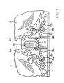
- Fig. 1 shows a partial view of a lower housing part 1 of a conventional video cassette with two reels 2, 3, the lower reel flanges 4a, b of which are serrated.
- the cassette also contains a locking mechanism, each with a pawl 6a, b which can be plugged and pivoted onto a post 5a, b.
- Their lever arm 7a, b also called the first lever arm
- the swiveling range of the first lever arm towards the spool is limited by the enveloping circle 8a, b - a circular depression in the cassette bottom.
- the other lever arm 9a, b (also called the second lever arm) rests on the release component 11 of the release lever 10.
- Wire springs 12a, b, one end of which rests on the first lever arm and the other end of which rests on a pin, are usually used to pretension the locking mechanism.
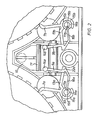
- the main feature of the invention is not only to replace the wire springs by a leaf spring made of plastic (also called a biasing arm), but to give the totality of the pawls a special geometric shape that minimizes deflection of the biasing arm when Swiveling of the pawls permitted.
- the two lever arms 7a, b and 9a, b are connected by a web 13a, b which runs at right angles to the lever arms.
- the lever arms and the web result in a U-shape.
- the distance between the lever arms is selected so that in order to perform their function (FIG. 2) the first lever arm engages in the locked position between the teeth of the lower coil flange and the free end of the second lever arm rests on the release component 11 of the release lever 10.
- their free end is rounded 14a, b.
- the pawl unit is integrally formed on a push-on sleeve 15a, b which is attached to the optionally hollow cylindrical post 5a, b.
- This particular geometric shape of the pawls is chosen in order to create the greatest possible effective spring length for the biasing arm 16a, b.
- the biasing arm is formed on the second lever arm and is so long that its free end 17a, b abuts the post, which is specially designed.
- the post itself can be designed as a bolt or as a sleeve which corresponds in height to that of the first lever arm. In order to be able to serve as a system for the prestressing arm, the free post end is therefore shaped semi-cylindrical 18a, b (FIG. 2).
- One of the two cut surfaces on the hollow cylindrical body is chamfered in such a way that the prestressing arm rests only on its inner edge 19a, b. This is a means of preventing the actuation force applied to the bias arm from pivoting when the pawls are pivoted. If the post end is annular, a slot 20 (Fig. 3) is sufficient to allow the biasing arm to rest.
- One of the two slotted surfaces should also be beveled, as described above. If the height of the post 5 corresponds to that of the push-on sleeve 15 of the pawl, a pin 21 (FIG. 4) arranged eccentrically on the post end can serve as an attachment.
- the second lever arm 9a is generally higher than the first, and can be shaped in an L-shape 22a at its lower end. The pre-tensioning arm adjoins the short leg of the lever arm, thereby increasing its effective length.
- Fig. 2 shows the pawls in engagement
- Fig. 5 shows the pawls in the release position.
- the pivot point of the pawls and the deflection point of the biasing arms are very close together.
- the material thickness of the pretensioning arm can be relatively thick compared to the solutions described at the outset, which precludes the plastic from fatigue at an early stage.
- Another advantage of the pawls according to the invention can be seen in the fact that they can be installed in the lower housing part of a commercially available cassette, only the system for the biasing arm having to be created. This can be achieved by injection molding with little effort.
Abstract
Videokassette mit zwei planparallel angeordneten Spulen zum Auf- und Abwickeln eines Magnetbandes und mit einem Sperrmechanismus bestehend aus einer auf einem Pfosten aufsteckbaren, schwenkbaren, zweiarmigen Sperrklinke für jede Spule, wobei in Außerbetriebstellung der Kassette ein Hebelarm in einen gezähnten Spulenflansch greift und der andere Hebelarm an dem Ausrückbauteil eines vertikal verdrehbaren Freigabehebels anliegt und je eines angeformten Vorspannarm, wobei der am Pfosten 5a, b gehäusefeste Auslenkpunkt 19a, b des Vorspannarmes 16a, b nahe der Drehachse der Sperrklinke liegt.Video cassette with two coils arranged in parallel for winding and unwinding a magnetic tape and with a locking mechanism consisting of a swiveling, two-armed pawl for each spool that can be plugged onto a post, with one lever arm engaging in a toothed spool flange and the other lever arm attacking when the cassette is not in use the disengaging component of a vertically rotatable release lever and one molded-on biasing arm each, the deflection point 19a, b of the biasing arm 16a, b fixed to the post 5a, b being close to the axis of rotation of the pawl.
Description
Die Erfindung betrifft einen Sperrmechanismus für Videokassetten, wobei die Sperrklinken in Verbindung mit den angeformten Vorspannarmen als Ersatz für die Drahtfedern eine besondere geometrische Form aufweisen.The invention relates to a locking mechanism for video cassettes, the pawls in connection with the molded biasing arms have a special geometric shape as a replacement for the wire springs.
Die handelsüblichen Videokassetten enthalten zwei planparallele Bandspulen, von denen das Magnetband auf- bzw. abgewickelt wird. Zum Abspielen auf dem Recorder wird das Band aus der Kassette gezogen. Um ein unbeabsichtigtes Lockern des Bandwickels bei Nichtgebrauch zu verhindern, enthalten die Kassetten Sperrvorrichtungen. Die dem Kassettenboden benachbarten Spulenflansche sind an ihrem Umfang gezähnt. Die schwenkbar gelagerten Sperrklinken selbst bestehen aus zweiarmigen Hebeln, deren einer Arm bei Nichtgebrauch an einer gezähnten Spule und deren zweiter Arm an einem Freigabehebel anliegt. Die Vorspannung der Sperrklinken erfolgt mittels einer Drahtfeder für jede der beiden Sperrklinken. Ein Federende greift an einem Hebelarm an, während das andere Ende sich an einem Stift abstützt. Durch den Einsatz von Drahtfedern werden die Herstellungskosten einer Videokassette ungünstig beeinflußt, denn die Federn bedingen Lagerhalterung, Qualitätsprüfung u.s.w.; auch der Einbau ist angesichts des beengten Innenraums einer Kassette mühsam. Um diese Nachteile zu vermeiden, wurde bereits verschiedentlich vorgeschlagen, die Drahtfedern durch angespritzte Kunststoffedern an den Sperrklinken zu ersetzen. So wurden in DE 27 54 935 gekrümmte Vorspannarme aus Kunststoff, die einerseits am Hebelarm der Sperrklinke angespritzt sind und sich andererseits an der Innenseite der Kassette abstützen, beschrieben. Ähnliches gilt auch für DE 28 20 866. In DE 28 37 886 wird anstelle von Drahtfedern eine einzige federnde Platte mit einem flachen und zwei gebogenen Teile verwendet. Der flache Teil liegt an der Seitenwand des Gehäuseunterteils an, die gebogenen Bereiche berühren die Sperrklinken. In DE 33 -28 353 und GM 81 21 098 ist an den Sperrklinken ein federelastischer Arm aus Kunststoff angespritzt, der sich gegen einen stationären Stift bzw. an der Innenseite der Kassette abstützt. In GB 20 99 400 oder US 42 32 840 wird ein einziger, gekrümmter Kunststoffarm verwendet. Die beiden Enden sind an den beiden benachbarten Hebelarmen der Sperrklinken angespritzt, während der gekrümmte Teil gegen die Innenwand des Kassettengehäuses drückt.The commercially available video cassettes contain two plane-parallel reels, from which the magnetic tape is wound up or unwound. The tape is pulled out of the cassette to be played on the recorder. The cassettes contain locking devices to prevent unintentional loosening of the tape reel when not in use. The coil flanges adjacent to the cassette bottom are serrated on their circumference. The pivoted pawls themselves consist of two-armed levers, one arm of which rests against a toothed spool when not in use and the second arm of which rests on a release lever. The pawls are pretensioned by means of a wire spring for each of the two pawls. One end of the spring engages a lever arm, while the other end is supported on a pin. The use of wire springs has an unfavorable effect on the production costs of a video cassette, because the springs require storage, quality inspection, etc.; Installation is also tedious given the narrow interior of a cassette. In order to avoid these disadvantages, various proposals have already been made to replace the wire springs with molded plastic springs on the pawls. So in DE 27 54 935 curved biasing arms made of plastic, the are molded on the lever arm of the pawl and are supported on the inside of the cassette. The same applies to DE 28 20 866. In DE 28 37 886 a single resilient plate with a flat and two curved parts is used instead of wire springs. The flat part lies against the side wall of the lower housing part, the curved areas touch the pawls. In DE 33 -28 353 and GM 81 21 098, a spring-elastic plastic arm is molded onto the pawls, which is supported against a stationary pin or on the inside of the cassette. In GB 20 99 400 or US 42 32 840 a single, curved plastic arm is used. The two ends are molded onto the two adjacent lever arms of the pawls, while the curved part presses against the inner wall of the cassette housing.
In all den genannten Fällen bedarf es einer relativ grossen Biegespannung bei der Betätigung der Kunststoffedern, d.h. die Federn müssen aus Elastizitätsgründen ebenso einen-relativ dünnen Querschnitt aufweisen, was ein frühzeitiges Ermüden des Materials zur Folge hat.In all the cases mentioned, a relatively large bending stress is required when actuating the plastic springs, i.e. for reasons of elasticity, the springs must also have a relatively thin cross section, which leads to premature fatigue of the material.
Um diese Nachteile zu umgehen, ist es notwendig die Biegespannung der Federelemente bzw. Vorspannarme herabzusetzen.In order to avoid these disadvantages, it is necessary to reduce the bending stress of the spring elements or preload arms.
Erfindungsgemäß wird diese Aufgabe gelöst, dadurch daß der am Pfosten 5a, b gehäusefeste Auslenkpunkt 19a, b des Vorspannarmes 16a, b nahe an der Drehachse der Sperrklinken liegt. In jedem Fall hat der Auslenkpunkt zur Drehachse der Sperrklinke einen kleineren Abstand als der Radius des Pfostens ist.According to the invention, this object is achieved in that the
Diese geringe physikalische Hebellänge erzeugt bei einem relativ grossen Federquerschnitt eine entsprechende Kraft zur Betätigung der Sperrklinke im Sperr- und Freigabestellung. Für die Funktionssicherheit ist es von erheblicher Bedeutung, daß infolge der geringen Auslenkung des Vorspannarmes ein frühzeitiges Ermüden des Kunststoffs verhindert wird.With a relatively large spring cross section, this small physical lever length generates a corresponding force for actuating the pawl in the locking and release position. For functional safety, it is of considerable importance that the plastic is prevented from tiring prematurely due to the slight deflection of the pretensioning arm.
Details der Erfindung sind in der Beschreibung und den Unteransprüchen wiedergegeben. Im Folgenden wird die Erfindung anhand von Zeichnungen näher erläutert und zwar zeigen
- Fig. l eine Teilaufsicht auf ein Gehäuseunterteil einer Videobandkassette entsprechend dem Stand der Technik mit Sperrklinken und vorgespannten Drahtfedern,
- Fig. 2 eine ebensolche Teilaufsicht mit den erfindungsgemäßen Sperrklinken in Sperrstellung,
- Fig. 3 eine Teilaufsicht mit geschlitzten zylindrischen Pfostenende,
- Fig. 4 eine Teilaufsicht auf eine erfindungsgemäße Sperrklinke mit am Pfostenende angeformten Stift,
- Fig. 5 eine Teilaufsicht entsprechend Fig. 2 mit den erfindungsgemäßen Sperrklinken in Freigabestellung.
- 1 is a partial view of a lower housing part of a video tape cassette according to the prior art with pawls and pretensioned wire springs,
- 2 is a similar partial supervision with the pawls according to the invention in the locked position,
- 3 is a partial top view with a slotted cylindrical post end,
- 4 is a partial view of a pawl according to the invention with a pin molded onto the post end,
- Fig. 5 is a partial supervision corresponding to Fig. 2 with the pawls according to the invention in the release position.
Fig. 1 stellt eine Teilaufsicht auf ein Gehäuseunterteil 1 einer herkömmlichen Videokassette dar mit zwei Bandspulen 2,3, deren untere Spulenflansche 4a,b qezähnt sind. Die Kassette enthält ferner einen Sperrmechanismus mit je einer auf einem Pfosten 5a, b aufsteckbaren und schwenkbaren Sperrklinke 6a, b. Deren einer Hebelarm 7a, b (auch erster Hebelarm genannt) verhindert beim Eingreifen zwischen die Zähne des Spulenflansches eine unerwünschte Drehung der Spulen. Der Schwenkbereich des ersten Hebelarmes auf die Spule zu ist durch den Hüllkreis 8a, b - eine kreisförmige Vertiefung im Kassettenboden - begrenzt. Der andere Hebelarm 9a, b (auch zweiter Hebelarm genannt) liegt am Ausrückbauteil 11 des Freigabehebels 10 an. Zur Vorspannung des Sperrmechanismus dienen üblicherweise Drahtfedern 12a, b, deren eines Ende am ersten Hebelarm und deren anderes Ende an einem Stift anliegt. Wie in Fig. 2 gezeigt, liegt das Hauptmerkmal der Erfindung darin, nicht nur die Drahtfedern durch eine Blattfeder aus Kunststoff (auch Vorspannarm genannt) zu ersetzen, sondern der Gesamtheit der Sperrklinken eine besondere geometrische Form zu geben, die eine möglichst geringe Auslenkung des Vorspannarmes beim Verschwenken der Sperrklinken gestattet. Dazu sind die beiden Hebelarme 7a, b und 9a, b durch einen Steg 13a, b verbunden, der im rechten Winkel zu den Hebelarmen verläuft. Die Hebelarme und der Steg ergeben eine U-Form. Der Abstand zwischen den Hebelarmen ist so gewählt, daß zur Erbringung ihrer Funktion (Fig. 2) der erste Hebelarm in Sperrstellung zwischen die Zähne des unteren Spulenflansches in Eingriff kommt und das freie Ende des zweiten Hebelarmes am Ausrückbauteil 11 des Freigabehebels 10 anliegt. Um beim Auslenken des Freigabehebels ein einwandfreies Abrollen der Hebelarme zu erreichen, ist deren freies Ende abgerundet 14a, b. Die Sperrklinkeneinheit ist an eine Aufsteckhülse 15a, b angeformt, die auf den gegebenenfalls hohlzylindrischen Pfosten 5a, b aufgesteckt wird. Diese besondere geometrische Form der Sperrklinken ist gewählt, um für den Vorspannarm 16a, b eine größtmögliche, wirksame Federlänge zu schaffen. Der Vorspannarm ist am zweiten Hebelarm angeformt und so lang, daß sein freies Ende 17a, b am Pfosten, der besonders ausgebildet ist, anliegt. Der Pfosten selbst kann als Bolzen oder als Hülse, die in der Höhe mit der des ersten Hebelarmes übereinstimmt, gestaltet sein. Um als Anlage für den Vorspannarm dienen zu können, ist deshalb das freie Pfostenende halbzylindrisch 18a, b (Fig. 2) geformt. Die eine der beiden Schnittflächen am hohlzylindrischen Körper ist derart abgeschrägt, daß die Auflage des Vorspannarmes nur an deren Innenkante 19a, b erfolgt. Dies ist ein Mittel, um die Betätigungskraft, die auf den Vorspannarm beim Schwenken der Sperrklinken ausgeübt wird, nicht zu stark werden zu lassen. Wenn das Pfostenende ringförmig ausgebildet ist, genügt ein Schlitz 20 (Fig. 3), um den Vorspannarm anliegen zu lassen.Fig. 1 shows a partial view of a lower housing part 1 of a conventional video cassette with two
Die eine der beiden Schlitzflächen soll ebenso, wie oben geschildert, abgeschrägt sein. Wenn die Höhe des Pfostens 5 mit der der Aufsteckhülse 15 der Sperrklinke übereinstimmt, kann ein auf den Pfostenende exzentrisch angeordneter Stift 21 (Fig. 4) als Anlage dienen. Der zweite Hebelarm 9a ist im allgemeinen höher als der erste, er läßt sich an seinem unteren Ende L-förmig 22a formen. An dem kurzen Schenkel des Hebelarmes schließt sich der Vorspannarm an, wodurch eine Vergrösserung seiner wirksamen Länge erreicht wird.One of the two slotted surfaces should also be beveled, as described above. If the height of the post 5 corresponds to that of the push-on
In Fig. 2 und 5 läßt sich der besondere Vorteil der Erfindung erkennen. Fig. 2 zeigt die Sperrklinken im Eingriff, Fig. 5 die Sperrklinken in Freigabestellung. Wie ersichtlich, liegen Drehpunkt der Sperrklinken und Auslenkpunkt der Vorspannarme sehr nahe beieinander. Dadurch kann die Materialstärke des Vorspannarmes gegenüber den eingangs der Beschreibung geschilderten Lösungen relativ dick sein, was ein frühzeitiges Ermüden des Kunststoffes ausschließt. Ein weiterer Vorteil der erfindungsgemäßen Sperrklinken kann darin gesehen werden, daß sie sich in das Gehäuseunterteil einer handelsüblichen Kassette einbauen lassen, wobei lediglich die Anlage für den Vorspannarm geschaffen werden muß. Dies ist spritzgußtechnisch ohne großen Aufwand zu verwirklichen.2 and 5, the particular advantage of the invention can be seen. Fig. 2 shows the pawls in engagement, Fig. 5 shows the pawls in the release position. As can be seen, the pivot point of the pawls and the deflection point of the biasing arms are very close together. As a result, the material thickness of the pretensioning arm can be relatively thick compared to the solutions described at the outset, which precludes the plastic from fatigue at an early stage. Another advantage of the pawls according to the invention can be seen in the fact that they can be installed in the lower housing part of a commercially available cassette, only the system for the biasing arm having to be created. This can be achieved by injection molding with little effort.
Claims (9)
Applications Claiming Priority (2)
| Application Number | Priority Date | Filing Date | Title |
|---|---|---|---|
| DE19843444861 DE3444861A1 (en) | 1984-12-08 | 1984-12-08 | LOCKING MECHANISM FOR VIDEO TAPES |
| DE3444861 | 1984-12-08 |
Publications (3)
| Publication Number | Publication Date |
|---|---|
| EP0187241A2 true EP0187241A2 (en) | 1986-07-16 |
| EP0187241A3 EP0187241A3 (en) | 1987-01-07 |
| EP0187241B1 EP0187241B1 (en) | 1989-05-17 |
Family
ID=6252275
Family Applications (1)
| Application Number | Title | Priority Date | Filing Date |
|---|---|---|---|
| EP85114964A Expired EP0187241B1 (en) | 1984-12-08 | 1985-11-26 | Brake mechanism for video cassettes |
Country Status (4)
| Country | Link |
|---|---|
| US (1) | US4623105A (en) |
| EP (1) | EP0187241B1 (en) |
| JP (1) | JPH0746490B2 (en) |
| DE (2) | DE3444861A1 (en) |
Cited By (1)
| Publication number | Priority date | Publication date | Assignee | Title |
|---|---|---|---|---|
| WO1990000799A1 (en) * | 1988-07-12 | 1990-01-25 | Schueler Wolfgang | Videocassette with counter for indicating the number of viewings |
Families Citing this family (10)
| Publication number | Priority date | Publication date | Assignee | Title |
|---|---|---|---|---|
| US4801107A (en) * | 1986-10-22 | 1989-01-31 | Sotar, Inc. | Cassette locking system |
| US4823223A (en) * | 1987-04-21 | 1989-04-18 | Konica Corporation | Mechanism for locking tape reel in magnetic tape cassette |
| EP0568061A3 (en) * | 1992-05-01 | 1994-08-17 | Minnesota Mining & Mfg | Cassette base with triangular strengthening braces |
| JPH079243U (en) * | 1993-07-23 | 1995-02-10 | 資子 桜井 | Free pipe of vacuum cleaner |
| US5505397A (en) * | 1994-07-22 | 1996-04-09 | Goff; Dewain R. | One-piece videocassette reel lock system |
| JP3473873B2 (en) * | 1995-03-23 | 2003-12-08 | 富士写真フイルム株式会社 | Magnetic tape cassette |
| JP3473872B2 (en) * | 1995-04-07 | 2003-12-08 | 富士写真フイルム株式会社 | Magnetic tape cassette |
| KR100211868B1 (en) * | 1996-04-25 | 1999-08-02 | 전주범 | Reel brake appararus in vcr |
| JP3027120B2 (en) * | 1996-06-11 | 2000-03-27 | ティーディーケイ株式会社 | Tape cassette |
| DE10227179A1 (en) * | 2001-06-19 | 2003-01-23 | Fuji Photo Film Co Ltd | Recording tape cartridge |
Citations (7)
| Publication number | Priority date | Publication date | Assignee | Title |
|---|---|---|---|---|
| FR2390801A1 (en) * | 1977-05-11 | 1978-12-08 | Minnesota Mining & Mfg | CLOSING MECHANISM FOR VIDEOCASSETTES |
| US4163533A (en) * | 1976-12-10 | 1979-08-07 | Sony Corporation | Tape cassette |
| GB2020628A (en) * | 1978-05-08 | 1979-11-21 | Sony Corp | Tape cassettes |
| US4195797A (en) * | 1977-11-18 | 1980-04-01 | Tdk Electronics Company, Limited | Tape cassette |
| GB2099400A (en) * | 1981-05-07 | 1982-12-08 | Victor Company Of Japan | Brake mechanism in a tape cassette |
| FR2508223A1 (en) * | 1981-06-22 | 1982-12-24 | Sony Corp | MAGNETIC TAPE CASSETTE |
| GB2125008A (en) * | 1982-08-12 | 1984-02-29 | Memorex Home Video Corp | Cassette reel lock |
Family Cites Families (2)
| Publication number | Priority date | Publication date | Assignee | Title |
|---|---|---|---|---|
| GB2019356B (en) * | 1978-03-23 | 1982-04-21 | Sony Corp | Tape cassette |
| JPS56103984U (en) * | 1979-12-29 | 1981-08-14 |
-
1984
- 1984-12-08 DE DE19843444861 patent/DE3444861A1/en not_active Withdrawn
-
1985
- 1985-11-26 EP EP85114964A patent/EP0187241B1/en not_active Expired
- 1985-11-26 DE DE8585114964T patent/DE3570307D1/en not_active Expired
- 1985-11-27 US US06/802,234 patent/US4623105A/en not_active Expired - Fee Related
- 1985-12-03 JP JP60270847A patent/JPH0746490B2/en not_active Expired - Lifetime
Patent Citations (7)
| Publication number | Priority date | Publication date | Assignee | Title |
|---|---|---|---|---|
| US4163533A (en) * | 1976-12-10 | 1979-08-07 | Sony Corporation | Tape cassette |
| FR2390801A1 (en) * | 1977-05-11 | 1978-12-08 | Minnesota Mining & Mfg | CLOSING MECHANISM FOR VIDEOCASSETTES |
| US4195797A (en) * | 1977-11-18 | 1980-04-01 | Tdk Electronics Company, Limited | Tape cassette |
| GB2020628A (en) * | 1978-05-08 | 1979-11-21 | Sony Corp | Tape cassettes |
| GB2099400A (en) * | 1981-05-07 | 1982-12-08 | Victor Company Of Japan | Brake mechanism in a tape cassette |
| FR2508223A1 (en) * | 1981-06-22 | 1982-12-24 | Sony Corp | MAGNETIC TAPE CASSETTE |
| GB2125008A (en) * | 1982-08-12 | 1984-02-29 | Memorex Home Video Corp | Cassette reel lock |
Cited By (1)
| Publication number | Priority date | Publication date | Assignee | Title |
|---|---|---|---|---|
| WO1990000799A1 (en) * | 1988-07-12 | 1990-01-25 | Schueler Wolfgang | Videocassette with counter for indicating the number of viewings |
Also Published As
| Publication number | Publication date |
|---|---|
| DE3570307D1 (en) | 1989-06-22 |
| DE3444861A1 (en) | 1986-06-12 |
| EP0187241B1 (en) | 1989-05-17 |
| JPH0746490B2 (en) | 1995-05-17 |
| US4623105A (en) | 1986-11-18 |
| EP0187241A3 (en) | 1987-01-07 |
| JPS61139987A (en) | 1986-06-27 |
Similar Documents
| Publication | Publication Date | Title |
|---|---|---|
| DE2832156C2 (en) | Magnetic tape cassette with a device for keeping the magnetic tape section running between two reels taut | |
| DE2918271C2 (en) | ||
| EP0187241B1 (en) | Brake mechanism for video cassettes | |
| DE2754771A1 (en) | REWINDING TAPE MEASURING DEVICE AND REPLACEABLE CARTRIDGE FOR IT | |
| EP1257744B1 (en) | Fixing device for securing an actuating cable | |
| DE2926956C3 (en) | Magnetic tape cassette with erasure protection | |
| DE2210709A1 (en) | Magnetic tape reel cassette | |
| CH556632A (en) | Lawn edge cutter with cutting wire - wire protrudes between round teeth on top disc around coil | |
| DE3132582A1 (en) | REEL FOR VIDEO TAPES | |
| DE8420207U1 (en) | TAPE CASSETTE, IN PARTICULAR MAGNETIC TAPE CASSETTE | |
| DE2756023C3 (en) | Cable winder with a cable drum | |
| DE102015004972B4 (en) | retractor | |
| EP0077972B1 (en) | Clamping spool with a hook-like projection | |
| DE2837886C3 (en) | Tape cartridge | |
| DE8436000U1 (en) | LOCKING MECHANISM FOR VIDEO TAPES | |
| DE3411926A1 (en) | DEVICE FOR ADJUSTING BARRIERS ON REELERS | |
| DE7920471U1 (en) | MAGNETIC TAPE CASSETTE | |
| DE2321782A1 (en) | CASSETTE LOCKING MECHANISM FOR TAPE RECORDS | |
| DE3022530A1 (en) | DEVICE FOR PREVENTING A MOTHER'S LOSS | |
| DE2641340C3 (en) | Rotary connection as part of a door handle operating mechanism and a metal rod rotatably arranged therein | |
| DE3439453A1 (en) | FINE CONTROL DEVICE | |
| DE2540671A1 (en) | Safety belt take up mechanism - has return spring operated take up spool fitted in exchangeable housing | |
| DE4134057C2 (en) | Tape cassette | |
| DE1948655C3 (en) | ||
| DE2014872A1 (en) | Playback cassette for a motion picture projector |
Legal Events
| Date | Code | Title | Description |
|---|---|---|---|
| PUAI | Public reference made under article 153(3) epc to a published international application that has entered the european phase |
Free format text: ORIGINAL CODE: 0009012 |
|
| 17P | Request for examination filed |
Effective date: 19851126 |
|
| AK | Designated contracting states |
Kind code of ref document: A2 Designated state(s): DE FR GB IT NL |
|
| PUAL | Search report despatched |
Free format text: ORIGINAL CODE: 0009013 |
|
| AK | Designated contracting states |
Kind code of ref document: A3 Designated state(s): DE FR GB IT NL |
|
| RAP1 | Party data changed (applicant data changed or rights of an application transferred) |
Owner name: AGFA-GEVAERT AG |
|
| 17Q | First examination report despatched |
Effective date: 19880427 |
|
| GRAA | (expected) grant |
Free format text: ORIGINAL CODE: 0009210 |
|
| AK | Designated contracting states |
Kind code of ref document: B1 Designated state(s): DE FR GB IT NL |
|
| ITF | It: translation for a ep patent filed |
Owner name: ING. C. GREGORJ S.P.A. |
|
| GBT | Gb: translation of ep patent filed (gb section 77(6)(a)/1977) | ||
| REF | Corresponds to: |
Ref document number: 3570307 Country of ref document: DE Date of ref document: 19890622 |
|
| ET | Fr: translation filed | ||
| PLBE | No opposition filed within time limit |
Free format text: ORIGINAL CODE: 0009261 |
|
| STAA | Information on the status of an ep patent application or granted ep patent |
Free format text: STATUS: NO OPPOSITION FILED WITHIN TIME LIMIT |
|
| 26N | No opposition filed | ||
| ITPR | It: changes in ownership of a european patent |
Owner name: CESSIONE;BASF MAGNETICS GMBH |
|
| NLS | Nl: assignments of ep-patents |
Owner name: BASF MAGNETICS GMBH TE MANNHEIM, BONDSREPUBLIEK DU |
|
| ITTA | It: last paid annual fee | ||
| REG | Reference to a national code |
Ref country code: FR Ref legal event code: TP |
|
| REG | Reference to a national code |
Ref country code: GB Ref legal event code: 732 |
|
| PGFP | Annual fee paid to national office [announced via postgrant information from national office to epo] |
Ref country code: NL Payment date: 19921130 Year of fee payment: 8 |
|
| PGFP | Annual fee paid to national office [announced via postgrant information from national office to epo] |
Ref country code: FR Payment date: 19931018 Year of fee payment: 9 |
|
| PGFP | Annual fee paid to national office [announced via postgrant information from national office to epo] |
Ref country code: GB Payment date: 19931115 Year of fee payment: 9 |
|
| PGFP | Annual fee paid to national office [announced via postgrant information from national office to epo] |
Ref country code: DE Payment date: 19931123 Year of fee payment: 9 |
|
| PG25 | Lapsed in a contracting state [announced via postgrant information from national office to epo] |
Ref country code: NL Effective date: 19940601 |
|
| NLV4 | Nl: lapsed or anulled due to non-payment of the annual fee | ||
| PG25 | Lapsed in a contracting state [announced via postgrant information from national office to epo] |
Ref country code: GB Effective date: 19941126 |
|
| GBPC | Gb: european patent ceased through non-payment of renewal fee |
Effective date: 19941126 |
|
| PG25 | Lapsed in a contracting state [announced via postgrant information from national office to epo] |
Ref country code: FR Effective date: 19950731 |
|
| PG25 | Lapsed in a contracting state [announced via postgrant information from national office to epo] |
Ref country code: DE Effective date: 19950801 |
|
| REG | Reference to a national code |
Ref country code: FR Ref legal event code: ST |