EP0185864B2 - Punktions- und Einführungsbesteck - Google Patents
Punktions- und Einführungsbesteck Download PDFInfo
- Publication number
- EP0185864B2 EP0185864B2 EP85112848A EP85112848A EP0185864B2 EP 0185864 B2 EP0185864 B2 EP 0185864B2 EP 85112848 A EP85112848 A EP 85112848A EP 85112848 A EP85112848 A EP 85112848A EP 0185864 B2 EP0185864 B2 EP 0185864B2
- Authority
- EP
- European Patent Office
- Prior art keywords
- puncture
- housing
- plug
- wire
- cannula
- Prior art date
- Legal status (The legal status is an assumption and is not a legal conclusion. Google has not performed a legal analysis and makes no representation as to the accuracy of the status listed.)
- Expired - Lifetime
Links
- 238000003780 insertion Methods 0.000 title claims abstract description 10
- 230000037431 insertion Effects 0.000 title claims abstract description 10
- 229910000831 Steel Inorganic materials 0.000 claims abstract description 30
- 239000010959 steel Substances 0.000 claims abstract description 30
- 238000007789 sealing Methods 0.000 claims abstract description 16
- 230000000284 resting effect Effects 0.000 claims abstract 2
- 239000000463 material Substances 0.000 claims description 2
- 239000002184 metal Substances 0.000 claims description 2
- 229920003023 plastic Polymers 0.000 claims description 2
- 238000002347 injection Methods 0.000 description 7
- 239000007924 injection Substances 0.000 description 7
- 210000001124 body fluid Anatomy 0.000 description 6
- 239000010839 body fluid Substances 0.000 description 6
- FAPWRFPIFSIZLT-UHFFFAOYSA-M Sodium chloride Chemical compound [Na+].[Cl-] FAPWRFPIFSIZLT-UHFFFAOYSA-M 0.000 description 4
- 239000000523 sample Substances 0.000 description 4
- 210000000056 organ Anatomy 0.000 description 3
- 239000002872 contrast media Substances 0.000 description 2
- 210000003238 esophagus Anatomy 0.000 description 2
- 239000012530 fluid Substances 0.000 description 2
- 210000003734 kidney Anatomy 0.000 description 2
- 238000000034 method Methods 0.000 description 2
- 239000011780 sodium chloride Substances 0.000 description 2
- 239000000243 solution Substances 0.000 description 2
- 101100008046 Caenorhabditis elegans cut-2 gene Proteins 0.000 description 1
- 239000003146 anticoagulant agent Substances 0.000 description 1
- 229940127219 anticoagulant drug Drugs 0.000 description 1
- 210000001367 artery Anatomy 0.000 description 1
- 210000000013 bile duct Anatomy 0.000 description 1
- 230000000903 blocking effect Effects 0.000 description 1
- 230000006835 compression Effects 0.000 description 1
- 238000007906 compression Methods 0.000 description 1
- 238000011109 contamination Methods 0.000 description 1
- 230000007812 deficiency Effects 0.000 description 1
- 230000010339 dilation Effects 0.000 description 1
- 238000006073 displacement reaction Methods 0.000 description 1
- 210000000244 kidney pelvis Anatomy 0.000 description 1
- 239000007788 liquid Substances 0.000 description 1
- 210000004185 liver Anatomy 0.000 description 1
- 230000000149 penetrating effect Effects 0.000 description 1
- 229920000642 polymer Polymers 0.000 description 1
- 239000002861 polymer material Substances 0.000 description 1
- 238000002360 preparation method Methods 0.000 description 1
- 239000000126 substance Substances 0.000 description 1
- 210000003932 urinary bladder Anatomy 0.000 description 1
- 210000003462 vein Anatomy 0.000 description 1
Images
Classifications
-
- A—HUMAN NECESSITIES
- A61—MEDICAL OR VETERINARY SCIENCE; HYGIENE
- A61M—DEVICES FOR INTRODUCING MEDIA INTO, OR ONTO, THE BODY; DEVICES FOR TRANSDUCING BODY MEDIA OR FOR TAKING MEDIA FROM THE BODY; DEVICES FOR PRODUCING OR ENDING SLEEP OR STUPOR
- A61M25/00—Catheters; Hollow probes
- A61M25/01—Introducing, guiding, advancing, emplacing or holding catheters
- A61M25/06—Body-piercing guide needles or the like
Definitions
- the invention relates to a puncture and introducer for a catheter or the like, with features of the introducer mentioned in the preamble of claim 1.
- Puncturing body cavities e.g. B. renal pelvis, bile duct, bladder, veins and arteries happens very often for the subsequent insertion of a catheter or a probe.
- a stylet into the steel cannula which fills the lumen of the steel cannula and is generally of the same length as the steel cannula. Since the diameter of the catheter or probe to be inserted is often larger than the diameter of the steel cannula used for the puncture, a dilation of the puncture channel is necessary, which is done either with the conically shaped catheter tip or with at least one dilator.
- a wire-shaped guide part which can be a Seldinger wire, a Lunderquist wire or the like, is inserted after the stylet has been pulled out through the steel cannula.
- This guide part remains with its tip in the cavity, while its distal end protrudes from the skin.
- the puncture cannula is withdrawn over the wire.
- the dilator or catheter must be advanced into the cavity via the guide part. Only then is the guide part removed. This previously practiced procedure is cumbersome.
- the rubber-elastic plug of the known introducer has a thin membrane-like central area, in which a passage is formed without removing material.
- the plug is followed coaxially by a hat-shaped sealing element, the rounded tip of which is slotted to form two sealing lips.
- a cap firmly connected to the housing holds the axially consecutive parts together in a fixed manner via a perforated holding plate.
- the passage in the plug and the sealing lips of the hat-shaped sealing element practice the device on one passing elongated part from a slight pressure that is sufficient for sealing, but does not hinder the displacement of the part. You cannot puncture with the introducer because the introducer tube is not a puncture cannula and because the guiding part cannot be locked in the introductory tube with an axially immovable stylet.
- This puncture and introducer does not involve the step of replacing a stylet for the guide part, but problems arise during the puncture in that the guide part must be held in position by hand if it is to serve as a stylet for the steel cannula, but not it is ensured that its tip reliably closes with the rear edge of the steel cannula cut in order to prevent tissue from penetrating into the steel cannula lumen. In addition, it is not excluded that air is introduced into the vessel during the advancement of the guide part or that the puncture cannula slips out of the punctured organ.
- a "tubular needle” which consists of three nested, relatively displaceable flexible tubes and injection needles and which is used to successively inject different preparations in the area of the esophagus.
- Each tube is fitted with a tube attachment piece, and the two inner tubes each carry an injection cannula at their proximal end.
- the two tubes are locked together by means of a plug on the tube attachment piece of the middle tube which can be squeezed radially by axial pressure.
- the coupled tubes are pushed together until the injection cannula on the middle tube protrudes over the tip of the outermost tube and enables an injection.
- the inner tube is advanced and another injection can be made through its injection cannula.
- the "tubular needle” is not suitable for use as a puncture and introducer for a catheter, because it neither enables punch-free puncture with an indication of the puncture success, nor prevents air being carried in through a tube into the puncture cavity.
- the invention is based on the aim of creating a puncture and insertion device with a wire-shaped guide part, in which the end of the guide part is sealed with the rear edge of a steel cannula during puncture and in each application phase the introduction of air into the punctured body cavity or the uncontrolled outflow of body fluid through the cannula attachment to the outside is excluded.
- the rubber-elastic plug in the housing serves two purposes. On the one hand, it seals the entry of the wire-shaped guide part into the cannula attachment, so that no air is introduced into the punctured body cavity during the essentially frictionless advance of the guide part, and on the other hand the hole in the plug can be radially compressed to such an extent that the wire-shaped Guide part in the steel cannula is blocked so that it can neither slide forward nor back.
- the latter means that after fixing the guide part in the steel cannula in such a way that its tip lies in the eye of the steel cannula cut, there is an absolutely reliable stylet function of the guide part, ie no tissue can penetrate into the lumen of the steel cannula during the puncture. Since the user does not have to hold onto the guide part, he can devote himself fully to the puncture procedure, which makes finding the target area easier and safer.
- the wire-shaped guide part is sealed during the advance of the rubber-elastic plug, the degree of narrowing of its central passage is selected so that the smoothness of the guide part feed is practically not hindered.
- the passage can be very narrowed again by the compression fitting, and the plug holds the guide part in the respective position until the obstacle, for. B. is overcome by turning or tilting the entire instrument and the guide part can be advanced. This avoids unnecessary stress on the patient due to repeated puncture.
- an opening is formed in an advantageous embodiment of the invention in the wall of the housing below the plug, to which a hose with an end connector is connected.
- a syringe to the connector of the tube and draw off body fluid to z. B. to drain the kidney pool.
- a syringe attached to the connector of the tube during the puncture through the annular space in the steel cannula past the guide part, for example NaCl solution, which can be mixed with X-ray contrast agents or with anticoagulant substances, can be injected into the body cavity.
- the housing and the hose are advantageously made of transparent plastic.
- the guide part can be designed as a Seldinger wire, Lunderquist wire, rope strand, polymer wire, as a wire-shaped part covered with polymer material, as a hose closed at the front or as a rigid metal tube or rod.
- the puncture and insertion kit for a catheter, dilator, the inner part of a dilator set, a button probe or the like consists of a steel cannula 1 with a ground tip 2 and a cannula hub 3, the sealing and fixing device 4 and a guide part 5, which in the selected example is a Seldinger wire with a curved tip 5a.
- the guide part 5 is considerably longer than the steel cannula 1 and its outer diameter is somewhat smaller than the lumen of the steel cannula 1, so that an annular space is created for the passage of fluid.
- the sealing and fixing device 4 has a sleeve-shaped housing 6 with a cylindrical cavity of circular cross section, at one end of which an internal thread 7 is formed, while at the other end there is an external thread 8. Between the two ends of the housing 6, an annular shoulder 9 is formed in the cavity above the internal thread 7, so that the cavity receives a longer section of a larger diameter and a shorter section of a smaller diameter. On the outward-facing surface of the annular shoulder 9 there is a cylindrical, thick, rubber-elastic plug 11 which is fitted into the larger cavity section and projects into the smaller cavity section with a short extension. The plug 4 is penetrated by a central passage 12 which is aligned with a channel 13 in an outer cone 14 in the area of the internal thread 7.
- the outer cone 14 engages in an inner cone 15 of the cannula hub 3 when radial cams 16 are screwed into the inner thread 7 of the housing 6 at the edge of the cannula hub 3 and the housing 6 is firmly seated on the cannula hub 3.
- a screw ring 17 with an internal thread 18 can be screwed onto the external thread 8 of the housing 6.
- the screw ring 17 is closed by an annular base plate 19 to which an inwardly directed coaxial hollow connector 20 is attached.
- the hollow connector 20 ends within the screw ring 17 and its straight edge 21 interacts with the outer surface of the rubber-elastic plug 11 of the sealing element when the screw ring 17 is screwed more or less onto the housing 6.
- the central passage 12 of the rubber-elastic can be compressed by axially squeezing the rubber-elastic plug 11 by means of the axially movable hollow connector 20 Graft 11 are radially more or less narrowed.
- the former has the consequence that the Guide part 5 can be completely blocked so that it can no longer be moved and the housing 6 is closed watertight.
- a smaller passage constriction causes the guide part 5 to be displaceably sealed, so that air entry into the housing 6 is avoided when the guide part 5 is advanced.
- an opening 22 is formed in the area of a free housing cavity 10 between the inner ends of the plug 11 and the outer cone 14, to which a small side connector 23 is attached, to which one end of a thin tube 24 is attached.
- the free end of the hose 24 carries a connector 25 for connection to a syringe, not shown.
- the connector 25 is initially closed by means of a screw cap 26.
- the puncture and introducer set shown is used as follows:
- the screw ring 17 is set so that the hollow connector 20 practically does not deform the plug 11, so that the central passage 12 has the plug 11 essentially in its original diameter and the guide part 5 is freely displaceable.
- the guide part 5 in the steel cannula 1 is adjusted so that the tip 5a is flush with the rear edge of the cannula cut 2 and the entry of tissue into the lumen of the steel cannula 1 is prevented during the puncture.
- the screw ring 17 is tightened, the edge of the hollow connector 20 pressing axially against the rubber-elastic plug 11 and deforming it so that the passage 12 is radially narrowed until the guide part 5 is firmly clamped and can no longer be moved.
- the hose 24 with a NaCl solution With the help of the syringe not shown on the connector 25, the hose 24 with a NaCl solution, the z. B. X-ray contrast medium can be filled, and the body cavity is punctured. It is observed whether liquid runs out of the hose 24 or can be drawn off or injected. The respective status shows the function result.
- the screw ring 17 is then loosened to such an extent that the plug 11 no longer holds the guide part 5 but only surrounds it in a sealing manner while it is being advanced.
- the steel cannula 1 with the housing 6 is withdrawn via the guide part 5 and a catheter, a dilator, an inner part of a dilator set, a button probe or the like is pulled over the guide part 5 inserted into the body cavity.
Landscapes
- Health & Medical Sciences (AREA)
- Life Sciences & Earth Sciences (AREA)
- Hematology (AREA)
- Animal Behavior & Ethology (AREA)
- Engineering & Computer Science (AREA)
- Anesthesiology (AREA)
- Biomedical Technology (AREA)
- Heart & Thoracic Surgery (AREA)
- Biophysics (AREA)
- Pulmonology (AREA)
- General Health & Medical Sciences (AREA)
- Public Health (AREA)
- Veterinary Medicine (AREA)
- Media Introduction/Drainage Providing Device (AREA)
- Infusion, Injection, And Reservoir Apparatuses (AREA)
- Surgical Instruments (AREA)
- Measurement Of The Respiration, Hearing Ability, Form, And Blood Characteristics Of Living Organisms (AREA)
Description
- Die Erfindung bezieht sich auf ein Punktions- und Einführungsbesteck für einen Katheter oder dergleichen, mit Merkmalen des im Oberbegriff des Patentanspruchs 1 genannten Einführungsbesteckes.
- Die punktion von Körperhohlräumen, z. B. Nierenbecken, Gallengang, Blase, Venen und Arterien geschieht sehr häufig zum nachträglichen Einlegen eines Katheters oder einer Sonde. Um bei der Punktion zu verhindern, daß Gewebe in das Lumen der Stahlkanüle eintritt und dieses während der Punktion verstopft, ist es üblich, in die Stahlkanüle einen Mandrin einzusetzen, der das Lumen der Stahlkanüle ausfüllt und im allgemeinen gleiche Länge wie die Stahlkanüle hat. Da der Durchmesser des einzuführenden Katheters oder der Sonde häufig größer ist als der Durchmesser der zur Punktion benutzten Stahlkanüle, ist eine Dilatation des Stichkanals erforderlich, was entweder mit der konisch angeformten Katheterspitze oder mit mindestens einem Dilatator erfolgt. Um nun das Punktionsloch in der Wand des Hohlraumes und auch den Stichkanal nach Zurückziehen der Stahlkanüle wiederzufinden, wird nach Herausziehen des Mandrins durch die Stahlkanüle ein drahtförmiger Führungsteil eingeschoben, der ein Seldingerdraht, ein Lunderquist-Draht oder dergleichen sein kann. Dieser Führungsteil bleibt mit seiner Spitze in dem Hohlraum liegen, während sein patientenfernes Ende aus der Haut herausragt. Die Punktionskanüle wird über den Draht zurückgezogen. Danach muß in einem fünften Schritt der Dilatator bzw. der Katheter über den Führungsteil in den Hohlraum vorgeschoben werden. Erst dann wird der Führungsteil entfernt. Dieses bisher geübte Vorgehen ist umständlich. Außerdem besteht die Gefahr, daß man nach Herausziehen des einen Teiles aus der Punktionskanüle und vor Einführung des nächsten Teiles in die Punktionskanüle Luft oder Kontaminationen in das Gefäß einschleppt oder daß man z. B. durch Bewegungen des Patienten und des Organs, wie z. B. Leber oder Niere, mit der Punktionskanüle aus dem punktierten Organ herausrutscht. Diesen Mangel kann auch das eingangs erwähnte Einführungsbesteck (EP-A-51 718) nicht beheben, das ausschließlich zum Einführen von Kathetern und dergleichen bestimmt ist und nicht gleichzeitig ein Punktionsbesteck bildet.
- Der gummielastische Pfropfen des bekannten Einführungsbestecks besitzt einen dünnen membranartigen Mittelbereich, in dem ohne Materialentnahme ein Durchlaß ausgebildet ist. Auf den Pfropfen folgt koaxial ein hutförmiges Dichtungselement, dessen abgerundete Spitze zur Bildung von zwei Dichtlippen geschlitzt ist. Eine mit dem Gehäuse fest verbundene Kappe hält über eine gelochte Halteplatte die axial aufeinanderfolgenden Teile unveränderlich zusammen. Der Durchlaß im Pfropfen und die Dichtlippen des hutförmigen Dichtungselementes üben auf einen die Vorrichtung passierenden langgestreckten Teil einen leichten Druck aus, der zur Abdichtung genügt, jedoch die Verschiebung des Teiles nicht behindert. Punktieren kann man mit dem Einführungsbesteck nicht, weil das Einführungsrohr keine Punktionskanüle ist und weil der Führungsteil nicht axial unverschieblicher Mandrin in dem Einführungsrohr blockierbar ist.
- Inzwischen ist ein Punktions- und Einführungsbesteck entwickelt worden (Arrow arterial catheterization system EP-A-93 164), bei dem ein drahtförmiger Führungsteil für den Katheter oder dergleichen in einem Ansatzstück einer Stahlkanüle verschiebbar vorgesehen ist und bei dem nach erfolgreicher Punktion bei zurückgezogenem Führungsteil Körperfluid zu einem durchsichtigen Kanülenansatz zurückströmen und das Punktionsergebnis dort anzeigen kann. Bei diesem Punktions- und Einführungsbesteck entfällt zwar der Schritt des Austausches eines Mandrins gegen den Führungsteil, jedoch treten Probleme während der Punktion dadurch auf, daß der Führungsteil von Hand in Stellung gehalten werden muß, wenn er als Mandrin für die Stahlkanüle dienen soll, wobei nicht gewährleistet ist, daß zuverlässig seine Spitze mit dem hinteren Rand des Stahlkanülenschliffs abschließt, um ein Eindrigen von Gewebe in das Stahlkanülenlumen zu verhindern. Außerdem ist es nicht ausgeschlossen, daß während des Vorschubes des Führungsteiles Luft in das Gefäß eingeschleppt wird oder daß die Punktions-kanüle aus dem punktierten Organ herausrutscht.
- Ferner ist aus JP-Y-56-44710 eine "Schlauchnadel" bekannt, die aus drei ineinandersteckenden, relativ zueinander verschiebbaren flexiblen Schläuchen und Injektionsnadeln besteht und die dazu dient, nacheinander unterschiedliche Präparate im Bereich der Speiseröhre zu injizieren. Jeder Schlauch ist mit einem Schlauchansatzstück versehen, und die beiden inneren Schläuche tragen an ihrem proximalen Ende je eine Injektionskanüle. Um die beiden Injektionskanülen an dem inneren und dem mittleren Schlauch bei der Einführung der "Schlauchnadel" in die Speiseröhre beliebig gestaffelt zurückgezogen zu halten, werden die beiden Schläuche mittels eines durch axiale Pressung radial zusammenquetschbaren Pfropfens am Schlauchansatzstück des mittleren Schlauches miteinander verriegelt. Am Zielort werden die gekuppelten Schläuche gemeinsam vorgeschoben bis die Injektionskanüle am mittleren Schlauch über die Spitze des äußersten Schlauches vortritt und eine Injektion ermöglich. Nach Lösen der Verriegelung wird der innere Schlauch vorgeschoben, und durch seine Injektionskanüle kann eine weitere Injektion erfolgen. Zur Verwendung als Punktions- und Einführungsbesteck für einen Katheter ist die "Schlauchnadel" nicht geeignet, weil sie weder eine ausstanzungsfreie Punktion mit Anzeige des Punktionserfolges ermöglicht, noch das Einschleppen von Luft durch einen Schlauch in den Punktionshohlraum verhindert.
- Der Erfindung liegt die Augabe zugrunde, ein Punktions- und Einführungsbesteckt mit einem drahtförmigen Führungsteil zu schaffen, bei dem der Abschluß der Spitze des Führungsteiles mit dem hinteren Rand eines Stahlkanülenschliffs bei der Punktion gewährleistet ist und in jeder Anwendungsphase das Einschleppen von Luft in den punktierten Körperholraum bzw. das unkontrollierte Ausfließen von Körperfluid durch den Kanülenansatz nach außen ausgeschlossen ist.
- Diese Aufgabe wird erfindungsgemäß durch die Merkmale des Anspruchs 1 gelöst.
- Der freie innere Rand des Hohlstutzens wird bei Aufschrauben des Schraubringes auf das Gehäuse beliebig fest gegen den Pfropfen gepreßt und dieser verformt sich, wobei der Durchlaß radial verengt wird. Der gummielastische Pfropfen in dem Gehäuse erfüllt zwei Aufgaben. Zum einen dichtet es den Eintritt des drahtförmigen Führungsteiles in den Kanülenansatz ab, so daß während des im wesentlichen reibungsfreien Vorschubes des Führungsteiles keine Luft in den punktierten Körperhohlraum eingeschleppt wird und zum anderen kann das Loch in dem Pfropfen radial so weit zusammengedrückt werden, daß der drahtförmige Führungsteil in der Stahlkanüle blockiert ist, so daß er weder vor- noch zurückrutschen kann. Letzteres bedeutet, daß nach Fixierung des Führungsteiles in der Stahlkanüle derart, daß seine Spitze im Auge des Stahlkanülenschliffs liegt, eine absolut zuverlässige Mandrinfunktion des Führungsteiles gegeben ist, d. h. daß kein Gewebe während der Punktion in das Lumen der Stahlkanüle eindringen kann. Da der Anwender den Führungsteil nicht festhalten muß, kann er sich dem Punktionsvorgang voll widmen, wodurch das Auffinden des Zielgebietes erleichtert und sicherer wird. Nach Lockerung des Stopfens wird der drahtförmige Führungsteil während des Vorschubes von dem gummielastischen Pfropfen abdichtend umschlossen, wobei der Verengungsgrad seines zentralen Durchlasses so gewählt ist, daß die Leichtgängigkeit des Führungsteilvorschubes praktisch nicht behindert wird. Sobald sich während des Führungsteilvorschubes durch Hindernisse in der Körperpassage Unterbrechungen ergeben, kann der Durchlaß durch die Quetschverschraubung wieder sehr stark verengt werden, und der Pfropfen hält den Führungsteil in der jeweiligen Position solange fest, bis das Hindernis z. B. durch Drehen oder Verkanten des Gesamtinstrumentes überwunden ist und der Führungsteil weiter vorgeschoben werden kann. Hierdurch werden unnötige Belastungen des Patienten infolge wiederholter Punktion vermieden.
- Bei Benutzung als Punktionsbesteck muß das Gerät in der Lage sein, den Punktionserfolg anzuzeigen. Zu diesem Zweck ist in vorteilhafter Ausgestaltung der Erfindung in der Wand des Gehäuses unterhalb des Pfropfens eine Öffnung ausgebildet, an die ein Schlauch mit einem endseitigen Anschlußstück angeschlossen ist. Nach erfolgter Punktion eines Körperhohlraumes mit in der Stahlkanüle fixiertem Führungsteil strömt Körperfluid durch den Ringraum zwischen Führungsteil und Stahlkanüleninnenwand zurück, wird von dem wasserdicht abgesperrten Dichtungselement an einem axialen Austritt gehindert und verläßt das Gehäuse durch den Schlauch. Das Erscheinen von Körperfluid in dem Schlauch zeigt das Punktionsergebnis an. Durch angepaßte Bemessung des Ringraumes in bezug auf den Fluiddruck in dem zu punktierenden und zu katheterisierenden Körperhohlraum läßt sich die Anzeige des Punktionserfolges durch heraustropfendes Körperfluid beschleunigen. Außerdem ist es möglich, an das Anschlußstück des Schlauches eine Spritze anzusetzen und Körperfluid abzuziehen, um vor Einführung eines Katheters z. B. das Nierenbecken zu entwässern. Ferner kann man mit einer an das Anschlußstück des Schlauches angesetzten Spritze während der Punktion durch den Ringraum in der Stahlkanüle an dem Führungsteil vorbei beispielsweise NaCl-Lösung, die mit Röntgenkontrastmitteln oder mit gerinnungshemmenden Substanzen versetzt sein kann, in den Körperhohlraum injizieren.
- Das Gehäuse und der Schlauch bestehen vorteilhafterweise aus transparentem Kunststoff. Der Führungsteil kann als Seldingerdraht, Lunderquist-Draht, Seil-Litze, Polymerdraht, als mit Polymermaterial überzogener drahtförmiger Teil, als vorne geschlossener Schlauch oder starres Metallrohr bzw. Stab ausgebildet sein.
- In der Zeichnung ist ein Ausführungsbeispiel der Erfindung schematisch dargestellt. Es zeigen :
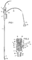
- Fig. 1 eine Draufsicht auf ein Punktions- und Einführungsbesteck und
- Fig. 2 die Abdichtungs- und Fixierungsvorrichtung im Längsschnitt im vergrößerten Maßstab.
- Das Punktions- und Einführungsbesteck für einen Katheter, Dilatator, den Innenteil eines Dilatatorsets, eine Knopfsonde oder dergleichen besteht aus einer Stahlkanüle 1 mit angeschliffener Spitze 2 und einem Kanülenansatz 3, aus der Abdichtungs- und Fixierungsvorrichtung 4 und aus einem Führungsteil 5, der bei dem gewählten Beispiel ein Seldingerdraht mit gekrümmter Spitze 5a ist. Der Führungsteil 5 ist beträchtlich länger als die Stahlkanüle 1 und sein Außendurchmesser ist etwas kleiner als das Lumen der Stahlkanüle 1, so daß ein Ringraum zum Durchlaß von Fluid entsteht.
- Die Abdichtungs- und Fixierungsvorrichtung 4 weist ein hülsenförmiges Gehäuse 6 mit zylindrischem Hohlraum von kreisförmigem Querschnitt auf, an dessen einem Ende ein Innengewinde 7 ausgebildet ist, während sich an seinem anderen Ende ein Außengewinde 8 befindet. Zwischen den beiden Enden des Gehäuses 6 ist über dem Innengewinde 7 in dem Hohlraum eine Ringschulter 9 ausgebildet, so daß der Hohlraum einen längeren Abschnitt größeren Durchmessers und einen kürzeren Abschnitt kleineren Durchmessers erhält. Auf der nach außen gerichteten Fläche der Ringschulter 9 liegt ein zylindrischer dicker, gummielastischer Pfropfen 11, der in dem größeren Hohlraumabschnitt eingepaßt ist und mit einem kurzen Fortsatz in den kleineren Hohlraumabschnitt ragt. Der Pfropfen 4 ist von einem zentralen Durchlaß 12 durchsetzt, welcher mit einem Kanal 13 in einem Außenkonus 14 im Bereich des Innengewindes 7 fluchtet. Der Außenkonus 14 greift in einen Innenkonus 15 des Kanülenansatzes 3 ein, wenn radiale Nocken 16 am Rand des Kanülenansatzes 3 in das Innengewinde 7 des Gehäuses 6 eingeschraubt sind und das Gehäuse 6 auf dem Kanülenansatz 3 festsitzt.
- Auf das Außengewinde 8 des Gehäuses 6 ist ein Schraubring 17 mit Innengewinde 18 aufschraubbar. Der Schraubring 17 ist durch eine ringförmige Bodenplatte 19 abgeschlossen, an der ein nach innen gerichteter koaxialer Hohlstutzen 20 befestigt ist. Der Hohlstutzen 20 endet innerhalb des Schraubringes 17 und sein gerader Rand 21 wirkt mit der Außenfläche des gummielastischen Pfropfens 11 des Dichtungselementes zusammen, wenn der Schraubring 17 mehr oder weniger auf das Gehäuse 6 aufgeschraubt wird. Wenn der drahtförmige Führungsteil 5 durch den Schraubring 17, den Hohlstutzen 20, den zentralen Durchlaß 12 und den Kanal 13 hindurch in die Stahlkanüle 1 eingeführt ist, kann durch axiales Zusammenquetschen des gummielastischen Pfropfens 11 mittels des axial beweglichen Hohlstutzens 20 der zentrale Durchlaß 12 des gummielastischen Pfropfens 11 radial mehr oder weniger verengt werden. Ersteres hat zur Folge, daß der Führungsteil 5 vollständig blockiert werden kann, so daß er nicht mehr verschiebbar ist und das Gehäuse 6 wasserdicht verschlossen ist. Geringere Durchlaßverengung bewirkt, daß der Führungsteil 5 abgedichtet verschiebbar ist, so daß Lufteintritt in das Gehäuse 6 beim Vorschieben des Führungsteiles 5 vermieden wird.
- In der Wand des Gehäuses 6 ist im Bereich eines freien Gehäusehohlraumes 10 zwischen den inneren Enden des Pfropfens 11 und des Außenkonus 14 eine Öffnung 22 ausgebildet, an die ein kleiner Seitenstutzen 23 angesetzt ist, an dem ein Ende eines dünnen Schlauches 24 befestigt ist. Das freie Ende des Schlauches 24 trägt ein Anschlußstück 25 zur Verbindung mit einer nicht gezeichneten Spritze. Das Anschlußstück 25 ist zunächst mittels einer Schraubkappe 26 verschlossen.
- Das dargestellte Punktions- und Einführungsbesteck wird wie folgt angewendet :
- Zunächst wird der Schraubring 17 so eingestellt, daß der Hohlstutzen 20 den Pfropfen 11 praktisch nicht verformt, so daß der zentrale Durchlaß 12 den Pfropfen 11 im wesentlichen seinen ursprünglichen Durchmesser aufweist und der Führungsteil 5 ungehindert frei verschiebbar ist. In diesem Zustand der Abdichtungs- und Fixierungsvorrichtung 4 wird der Führungsteil 5 in der Stahlkanüle 1 so justiert, daß die Spitze 5a mit dem hinteren Rand des Kanülenschliffs 2 abschließt und der Eintritt von Gewebe in das Lumen der Stahlkanüle 1 während der Punktion verhindert wird. Sodann wird der Schraubring 17 angezogen, wobei der Rand des Hohlstutzens 20 axial gegen den gummielastische Pfropfen 11 drückt und ihn so verformt, daß der Durchlaß 12 radial verengt wird, bis der Führungsteil 5 fest eingespannt ist und sich nicht mehr bewegen läßt. Mit Hilfe der nicht gezeichneten Spritze an dem Anschlußstück 25 wird der Schlauch 24 mit einer NaCl-Lösung, die z. B. Röntgenkontrastmittel enthalten kann, gefüllt und es wird der Körperhohlraum punktiert. Dabei wird beobachtet, ob Flüssigkeit aus dem Schlauch 24 abläuft oder sich abziehen bzw. injizieren läßt. Der jeweilige Status zeigt das Funktionsergebnis an. Anschließend wird der Schraubring 17 soweit gelockert, daß der Pfropfen 11 den Führungsteil 5 nicht mehr festhält, sondern ihn nur noch abdichtend umschließt, während er vorgeschoben wird. Wenn die Spitze 5a des Führungsteiles 5 die vorgesehene Position innerhalb des Körperhohlraumes eingenommen hat, wird die Stahlkanüle 1 mit dem Gehäuse 6 über den Führungsteil 5 zurückgezogen und es wird ein Katheter, ein Dilatator, ein Innenteil eines Dilatatorsets, eine Knopfsonde oder dergleichen über den Führungsteil 5 in den Körperhohlraum eingeführt.
Claims (5)
aus einer Abdichtungsvorrichtung (4), die an dem Kanülenansatz (3) angeordnet ist und einen in einem Gehäuse (6) untergebrachten, als Dichtungselement dienenden, gelochten gummielastischen Pfropfen (11) mit einem zentralen Durchlaß (12) für den Führungsteil (5) aufweist, der auf einer Ringschulter (9) des Gehäuses (6) liegt und mittels eines auf das Gehäuse (6) aufgeschraubten Druckkörpers (17,20) zusammenquetschbar ist, welcher einen gegen den gummielastischen Pfropfen (11) axial andrückbaren Hohlstutzen (20) aufweist, der den zentralen Durchlaß (12) des Pfropfens (11) radial zusammenquetscht, um den drahtförmigen Führungsteil (5) zu blockieren,
und aus einer in der Wand des Gehäuses (6) unterhalb des Pfropfens (11) ausgebildeten Öffnung (22), an die ein Schlauch (24) mit einem endseitigen Anschlußstück (25) angeschlossen ist.
Priority Applications (1)
| Application Number | Priority Date | Filing Date | Title |
|---|---|---|---|
| AT85112848T ATE39845T1 (de) | 1984-12-14 | 1985-10-10 | Punktions- und einfuehrungsbesteck. |
Applications Claiming Priority (2)
| Application Number | Priority Date | Filing Date | Title |
|---|---|---|---|
| DE8436618 | 1984-12-14 | ||
| DE8436618U | 1984-12-14 |
Publications (3)
| Publication Number | Publication Date |
|---|---|
| EP0185864A1 EP0185864A1 (de) | 1986-07-02 |
| EP0185864B1 EP0185864B1 (de) | 1989-01-11 |
| EP0185864B2 true EP0185864B2 (de) | 1992-01-29 |
Family
ID=6773755
Family Applications (1)
| Application Number | Title | Priority Date | Filing Date |
|---|---|---|---|
| EP85112848A Expired - Lifetime EP0185864B2 (de) | 1984-12-14 | 1985-10-10 | Punktions- und Einführungsbesteck |
Country Status (3)
| Country | Link |
|---|---|
| EP (1) | EP0185864B2 (de) |
| AT (1) | ATE39845T1 (de) |
| DE (1) | DE3567376D1 (de) |
Families Citing this family (4)
| Publication number | Priority date | Publication date | Assignee | Title |
|---|---|---|---|---|
| DE3731590C1 (en) * | 1987-09-19 | 1988-07-21 | Braun Melsungen Ag | Medical probe |
| DE3830653A1 (de) * | 1988-09-09 | 1990-03-22 | Braun Melsungen Ag | Besteck fuer die intrapleurale regionalanaesthesie |
| DE29503750U1 (de) * | 1995-03-04 | 1995-04-27 | B. Braun Melsungen Ag, 34212 Melsungen | Fixiervorrichtung |
| JP2006501013A (ja) * | 2002-09-30 | 2006-01-12 | 昌樹 藤村 | 胆道系手術後に胆汁を排出するために使用するチューブアセンブリ |
Family Cites Families (5)
| Publication number | Priority date | Publication date | Assignee | Title |
|---|---|---|---|---|
| DE2305640C3 (de) * | 1973-02-06 | 1975-08-14 | B. Braun Melsungen Ag, 3508 Melsungen | Vorrichtung zum Einführen flexibler Katheter |
| US4000739A (en) * | 1975-07-09 | 1977-01-04 | Cordis Corporation | Hemostasis cannula |
| US4235232A (en) * | 1978-08-22 | 1980-11-25 | Johnson & Johnson | Hub device for preventing liquid leakage |
| FR2474317A1 (fr) * | 1980-01-29 | 1981-07-31 | Technological Supply | Catheter de perfusion intraveineuse a valve hemostatique |
| DE3042229C2 (de) * | 1980-11-08 | 1983-10-27 | B. Braun Melsungen Ag, 3508 Melsungen | Einführungsvorrichtung zum Einbringen langgestreckter Gegenstände in Blutgefäße |
-
1985
- 1985-10-10 DE DE8585112848T patent/DE3567376D1/de not_active Expired
- 1985-10-10 EP EP85112848A patent/EP0185864B2/de not_active Expired - Lifetime
- 1985-10-10 AT AT85112848T patent/ATE39845T1/de not_active IP Right Cessation
Also Published As
| Publication number | Publication date |
|---|---|
| ATE39845T1 (de) | 1989-01-15 |
| DE3567376D1 (en) | 1989-02-16 |
| EP0185864B1 (de) | 1989-01-11 |
| EP0185864A1 (de) | 1986-07-02 |
Similar Documents
| Publication | Publication Date | Title |
|---|---|---|
| DE69318170T3 (de) | Einrichtung zur lokalisierung eines blutgefässes | |
| EP0624104B1 (de) | Katheterisierungsbesteck | |
| DE69122582T2 (de) | Drainagekatheter | |
| DE60307726T2 (de) | Verweilkatheteranordnung | |
| DE69026944T2 (de) | Kathetereinführungsspritze | |
| DE69313714T2 (de) | Vaskulare Eingangsvorrichtung | |
| DE10329126B4 (de) | Katheterapplikationssystem | |
| EP0339460B1 (de) | Medizinisches Einführungsbesteck | |
| DE3214905C2 (de) | ||
| DE69201874T2 (de) | Intravaskulärer mehrlumiger Katheter für das Implantieren mit Hilfe eines Tunnels. | |
| DE69115064T2 (de) | Katheter mit angesteuertem Ventil. | |
| DE19701546C1 (de) | Punktionsset | |
| DE2238722A1 (de) | Kathetereinfuehrungssystem | |
| DE2331333A1 (de) | Infusionsbesteck | |
| EP0433717A1 (de) | Punktionsbesteck | |
| DE2817974A1 (de) | Katheterabgabevorrichtung und verfahren zu ihrer verwendung | |
| DE3006291A1 (de) | Intravaskulaer-kathetervorrichtung | |
| DE2715198A1 (de) | Zur einfuehrung eines gefaesskatheters in die blutbahn geeignete teilbare kanuele | |
| DE3107392A1 (de) | Medizinisches instrument | |
| DE4128530C2 (de) | ||
| DE1566588B1 (de) | Vorrichtung zum Einfuehren eines Katheters | |
| DE3919740A1 (de) | Geraet zum einsetzen einer suprapubischen blasenfistel | |
| DE3900329A1 (de) | Besteck zur punktion eines koerperhohlraumes | |
| DE3444807A1 (de) | Katheter | |
| EP0185864B2 (de) | Punktions- und Einführungsbesteck |
Legal Events
| Date | Code | Title | Description |
|---|---|---|---|
| PUAI | Public reference made under article 153(3) epc to a published international application that has entered the european phase |
Free format text: ORIGINAL CODE: 0009012 |
|
| AK | Designated contracting states |
Kind code of ref document: A1 Designated state(s): AT BE CH DE FR GB IT LI LU NL SE |
|
| 17P | Request for examination filed |
Effective date: 19860524 |
|
| 17Q | First examination report despatched |
Effective date: 19870626 |
|
| RAP1 | Party data changed (applicant data changed or rights of an application transferred) |
Owner name: B. BRAUN-SSC AG |
|
| GRAA | (expected) grant |
Free format text: ORIGINAL CODE: 0009210 |
|
| AK | Designated contracting states |
Kind code of ref document: B1 Designated state(s): AT BE CH DE FR GB IT LI LU NL SE |
|
| REF | Corresponds to: |
Ref document number: 39845 Country of ref document: AT Date of ref document: 19890115 Kind code of ref document: T |
|
| ITF | It: translation for a ep patent filed | ||
| GBT | Gb: translation of ep patent filed (gb section 77(6)(a)/1977) | ||
| REF | Corresponds to: |
Ref document number: 3567376 Country of ref document: DE Date of ref document: 19890216 |
|
| ET | Fr: translation filed | ||
| PLBI | Opposition filed |
Free format text: ORIGINAL CODE: 0009260 |
|
| PG25 | Lapsed in a contracting state [announced via postgrant information from national office to epo] |
Ref country code: LU Free format text: LAPSE BECAUSE OF NON-PAYMENT OF DUE FEES Effective date: 19891031 |
|
| 26 | Opposition filed |
Opponent name: OLYMPUS OPTICAL COMPANY LTD. Effective date: 19890920 |
|
| NLR1 | Nl: opposition has been filed with the epo |
Opponent name: OLYMPUS OPTICAL COMPANY LTD. |
|
| ITTA | It: last paid annual fee | ||
| PUAH | Patent maintained in amended form |
Free format text: ORIGINAL CODE: 0009272 |
|
| STAA | Information on the status of an ep patent application or granted ep patent |
Free format text: STATUS: PATENT MAINTAINED AS AMENDED |
|
| 27A | Patent maintained in amended form |
Effective date: 19920129 |
|
| AK | Designated contracting states |
Kind code of ref document: B2 Designated state(s): AT BE CH DE FR GB IT LI LU NL SE |
|
| ITF | It: translation for a ep patent filed | ||
| REG | Reference to a national code |
Ref country code: CH Ref legal event code: AEN |
|
| ET3 | Fr: translation filed ** decision concerning opposition | ||
| NLR2 | Nl: decision of opposition | ||
| GBTA | Gb: translation of amended ep patent filed (gb section 77(6)(b)/1977) | ||
| NLR3 | Nl: receipt of modified translations in the netherlands language after an opposition procedure | ||
| PGFP | Annual fee paid to national office [announced via postgrant information from national office to epo] |
Ref country code: FR Payment date: 19920928 Year of fee payment: 8 |
|
| PGFP | Annual fee paid to national office [announced via postgrant information from national office to epo] |
Ref country code: GB Payment date: 19920929 Year of fee payment: 8 |
|
| PGFP | Annual fee paid to national office [announced via postgrant information from national office to epo] |
Ref country code: AT Payment date: 19921012 Year of fee payment: 8 |
|
| PGFP | Annual fee paid to national office [announced via postgrant information from national office to epo] |
Ref country code: CH Payment date: 19921014 Year of fee payment: 8 |
|
| PGFP | Annual fee paid to national office [announced via postgrant information from national office to epo] |
Ref country code: SE Payment date: 19921020 Year of fee payment: 8 |
|
| PGFP | Annual fee paid to national office [announced via postgrant information from national office to epo] |
Ref country code: NL Payment date: 19921031 Year of fee payment: 8 |
|
| PGFP | Annual fee paid to national office [announced via postgrant information from national office to epo] |
Ref country code: BE Payment date: 19921106 Year of fee payment: 8 |
|
| PGFP | Annual fee paid to national office [announced via postgrant information from national office to epo] |
Ref country code: DE Payment date: 19921127 Year of fee payment: 8 |
|
| NLT1 | Nl: modifications of names registered in virtue of documents presented to the patent office pursuant to art. 16 a, paragraph 1 |
Owner name: B. BRAUN HOLDING AG TE EMMENBRUECKE, ZWITSERLAND. |
|
| PG25 | Lapsed in a contracting state [announced via postgrant information from national office to epo] |
Ref country code: GB Effective date: 19931010 Ref country code: AT Effective date: 19931010 |
|
| PG25 | Lapsed in a contracting state [announced via postgrant information from national office to epo] |
Ref country code: SE Effective date: 19931011 |
|
| PG25 | Lapsed in a contracting state [announced via postgrant information from national office to epo] |
Ref country code: LI Effective date: 19931031 Ref country code: CH Effective date: 19931031 Ref country code: BE Effective date: 19931031 |
|
| BERE | Be: lapsed |
Owner name: B. BRAUN HOLDING A.G. Effective date: 19931031 |
|
| PG25 | Lapsed in a contracting state [announced via postgrant information from national office to epo] |
Ref country code: NL Effective date: 19940501 |
|
| GBPC | Gb: european patent ceased through non-payment of renewal fee |
Effective date: 19931010 |
|
| NLV4 | Nl: lapsed or anulled due to non-payment of the annual fee | ||
| PG25 | Lapsed in a contracting state [announced via postgrant information from national office to epo] |
Ref country code: FR Effective date: 19940630 |
|
| REG | Reference to a national code |
Ref country code: CH Ref legal event code: PL |
|
| PG25 | Lapsed in a contracting state [announced via postgrant information from national office to epo] |
Ref country code: DE Effective date: 19940701 |
|
| REG | Reference to a national code |
Ref country code: FR Ref legal event code: ST |
|
| EUG | Se: european patent has lapsed |
Ref document number: 85112848.8 Effective date: 19940510 |