EP0185552A2 - Vorrichtung zum Steuern des Betriebs eines Innenverbrennungsmotors - Google Patents
Vorrichtung zum Steuern des Betriebs eines Innenverbrennungsmotors Download PDFInfo
- Publication number
- EP0185552A2 EP0185552A2 EP85309254A EP85309254A EP0185552A2 EP 0185552 A2 EP0185552 A2 EP 0185552A2 EP 85309254 A EP85309254 A EP 85309254A EP 85309254 A EP85309254 A EP 85309254A EP 0185552 A2 EP0185552 A2 EP 0185552A2
- Authority
- EP
- European Patent Office
- Prior art keywords
- combustion engine
- internal combustion
- intake air
- variables
- air quantity
- Prior art date
- Legal status (The legal status is an assumption and is not a legal conclusion. Google has not performed a legal analysis and makes no representation as to the accuracy of the status listed.)
- Granted
Links
Images


Classifications
-
- F—MECHANICAL ENGINEERING; LIGHTING; HEATING; WEAPONS; BLASTING
- F02—COMBUSTION ENGINES; HOT-GAS OR COMBUSTION-PRODUCT ENGINE PLANTS
- F02D—CONTROLLING COMBUSTION ENGINES
- F02D41/00—Electrical control of supply of combustible mixture or its constituents
- F02D41/02—Circuit arrangements for generating control signals
- F02D41/14—Introducing closed-loop corrections
- F02D41/1401—Introducing closed-loop corrections characterised by the control or regulation method
-
- F—MECHANICAL ENGINEERING; LIGHTING; HEATING; WEAPONS; BLASTING
- F02—COMBUSTION ENGINES; HOT-GAS OR COMBUSTION-PRODUCT ENGINE PLANTS
- F02D—CONTROLLING COMBUSTION ENGINES
- F02D43/00—Conjoint electrical control of two or more functions, e.g. ignition, fuel-air mixture, recirculation, supercharging or exhaust-gas treatment
-
- F—MECHANICAL ENGINEERING; LIGHTING; HEATING; WEAPONS; BLASTING
- F02—COMBUSTION ENGINES; HOT-GAS OR COMBUSTION-PRODUCT ENGINE PLANTS
- F02B—INTERNAL-COMBUSTION PISTON ENGINES; COMBUSTION ENGINES IN GENERAL
- F02B1/00—Engines characterised by fuel-air mixture compression
- F02B1/02—Engines characterised by fuel-air mixture compression with positive ignition
- F02B1/04—Engines characterised by fuel-air mixture compression with positive ignition with fuel-air mixture admission into cylinder
-
- F—MECHANICAL ENGINEERING; LIGHTING; HEATING; WEAPONS; BLASTING
- F02—COMBUSTION ENGINES; HOT-GAS OR COMBUSTION-PRODUCT ENGINE PLANTS
- F02D—CONTROLLING COMBUSTION ENGINES
- F02D41/00—Electrical control of supply of combustible mixture or its constituents
- F02D41/02—Circuit arrangements for generating control signals
- F02D41/14—Introducing closed-loop corrections
- F02D41/1401—Introducing closed-loop corrections characterised by the control or regulation method
- F02D2041/1413—Controller structures or design
- F02D2041/1415—Controller structures or design using a state feedback or a state space representation
- F02D2041/1416—Observer
-
- F—MECHANICAL ENGINEERING; LIGHTING; HEATING; WEAPONS; BLASTING
- F02—COMBUSTION ENGINES; HOT-GAS OR COMBUSTION-PRODUCT ENGINE PLANTS
- F02D—CONTROLLING COMBUSTION ENGINES
- F02D41/00—Electrical control of supply of combustible mixture or its constituents
- F02D41/02—Circuit arrangements for generating control signals
- F02D41/14—Introducing closed-loop corrections
- F02D41/1401—Introducing closed-loop corrections characterised by the control or regulation method
- F02D2041/1413—Controller structures or design
- F02D2041/1426—Controller structures or design taking into account control stability
-
- F—MECHANICAL ENGINEERING; LIGHTING; HEATING; WEAPONS; BLASTING
- F02—COMBUSTION ENGINES; HOT-GAS OR COMBUSTION-PRODUCT ENGINE PLANTS
- F02D—CONTROLLING COMBUSTION ENGINES
- F02D41/00—Electrical control of supply of combustible mixture or its constituents
- F02D41/02—Circuit arrangements for generating control signals
- F02D41/14—Introducing closed-loop corrections
- F02D41/1401—Introducing closed-loop corrections characterised by the control or regulation method
- F02D2041/1433—Introducing closed-loop corrections characterised by the control or regulation method using a model or simulation of the system
Definitions
- the operating state detecting means M4 may be used, depending on the type of the internal combustion engine M1, an O 2 sensor which detects the concentration of oxygen within exhaust gasses, a knock sensor which detects knocking of internal combustion engine M1, a coolant temperature sensor which detects the temperature of coolant of the internal combustion engine M1, and an intake air temperature sensor.
- the target value setting means M5 sets a target value of the operating state including at least output torque and intake air quantity of the internal combustion engine M1 on the basis of the amount of demand to the internal combustion engine M1, and is arranged to compute a target output torque and intake air quantity corresponding to the manipulated stroke of the accelerator and the state of the transmission. Especially, it operates in the present invention to compute the target intake air quantity as an intake air quantity which makes the amount of fuel supplied to the internal combustion engine M1 minimum.
- the target intake air quantity which provides minimum amount of fuel supplied to the internal combustion engine M1 can be obtained as follows.
- Fig. 5 is a torque diagram showing the relationship between intake air quantity AR and fuel supply amount FR when output torque T of the internal combustion engine M1 is made constant Assuming that the internal combustion engine is operated when an intake air quantity is Ab, fuel supply amount is at point "b" of Fb, and output torque equals To, it will be understood that the fuel supply amount Fa becomes minimum at a point (Aa, Fa) where the intake air quantity has been incremented by ⁇ Ao from that at point "b".
- the target value setting means M5 is constructed so that the fuel supply amount FR is made minimum with respsect to the target value AR of the intake air quantity, and may be realized generally by a control performed by a microcomputer or the like as a part of a control means M6 which will be described hereinlater.
- state variable X (k) is an amount indicating the internal state of the internal combustion engine M1
- this is not required to be a variable corresponding to actual physical amount, and therefore, this may be designed as a vector of an appropriate order which is suitable for indicating the sate of the internal combustion engine M1.
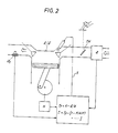
- Fig. 6 is a schematic structural diagram showing an internal combustion engine according to an embodiment of the present invention, and its peripheral units;
- Fig. 7 is a control system diagram showing a control model of a system where operating state of the internal combustion engine is controlled;
- Fig. 8 is a block diagram for the description of system identification;
- Fig. 9 is a flowchart showing one example of a control executed by an electronic control circuit;
- Fig. 10 is a flowchart showing one example of a control for obtaining intake air quantity with which fuel compution is made minimum; and the description will be given in this order.
- the input port 49 of the electronic control circuit 40 receives signals indicative of the amount of demand of the internal combustion engine 1 and its operating state from respective sensors. More specifically, it comprises an unshown analog input unit for receiving accelerator opening degree Acc from the accelerator opening degree sensor 37 as the amount of demand, intake air quantity AR from the airflow meter 3 as the opening state, intake air temperature Tha from the intake air temperature sensor 6, output torque T from the pressure sensor 27, coolant temperature Thw from the coolant temperature sensor 29 to A/C convert them and then to supply the same to the MPU 44 as data, and an unshown pulse input unit for receiving rotational speed N of the internal combustion engine 1 from the rotational speed sensor 31 and cylinder-determination signal from the cylinder-determination sensor 33.
- an unshown analog input unit for receiving accelerator opening degree Acc from the accelerator opening degree sensor 37 as the amount of demand, intake air quantity AR from the airflow meter 3 as the opening state, intake air temperature Tha from the intake air temperature sensor 6, output torque T from the pressure sensor 27, coolant temperature Thw from the coolant temperature sensor 29 to A
- the reference P5 indicates a perturbation component extracting portion which extracts a perturbation component from various values (Ta, ARa, Na) under the state where steady operating state in connection with output torque T, intake air quantity AR and rotational speed N.
- the condition of operation of the internal combustion engine 1, i.e. throttle opening degree ⁇ , a controlled variable relating to the fuel injection amount FR, which are obtained by the above-mentioned integrators P3, P4, the observer P6 and the feedback amount determining unit P7, are also handled as perturbation components ⁇ and ⁇ FR.
- the above-mentioned model having two inputs and three outputs is used for constructing the dynamic model of the internal combustion engine 1, and in addition to these coolant temperature Thw and intake air temperature
- the of the internal combustion engine 1 are also used as factors which change the dynamic behaviour of the system.
- the coolant temperature Thw and so on do not change the structure of the control system but changes the state of dynamic behaviour thereof. Therefore, when the dynamic model is constructed in connection with the control system of the internal combustion engine 1, the vectors A , B , Cof the state equation (1) and the output equation (2) are determined in accordance with the coolant temperature Thw and so on of the internal combustion engine 1.
- FIG. 8 is a diagram showing a system of the internal combustion engine 1 under steady state operation as a system having two inputs and three outputs by way of transfer functions G1(z) through G6(z).
- the reference z indicates z transformation of sampled values of the input/output signals, and it is assumed that G1(z) through G6(z) have appropriate order. Therefore, entire transfer function matrix G (z) is given by:
- the dynamic model of the present embodiment is obtained through system identification, and this dynamic model can be determined in the form that linear approximation is satisfied around a state where the internal combustion engine 1 operated under a given state. Therefore, the transfer function G1 (z) through G6(z) are respectively obtained through the above method in connection with a plurality of steady operating states, and respective state equations (1) and output equations (2), i.e. vectors A , B , C , are obtained where the relationship between input and output thereof is satisfied between perturbation components T.
- the MPU 44 executes repeatedly step 100 and following steps.
- the fuel injection valves 11 are opened and the throttle valve 7 is controlled via the actuator 35 using the fuel injection amount FR(k-1) and throttle valve opening degree ⁇ (k-1) both obtained in previous series of processings.
- the depressed stroke of the accelerator 38 is read by the accelerator sensor 37, and in a step 120 the operating state of the internal combustion engine 1, i.e. the output torque T(k-1), intake air quantity AR(k-1), and rotational speed N(k-1) and so on, is read from respective sensors.
- a nearest state (which will be referred to as operating points Ta, ARa, NA) among steady-state operating states taken as satisfying linear approximation when the dynamic model of the internal combustion engine 1 is constructed, is obtained from the operating state read in step 120.
- the operating state of the internal combustion engine 1 is obtained as perturbation components ( ⁇ T, ⁇ AR, ⁇ N) relative to the steady state points (Ta, ARa, Na). This processing corresponds to the perturbation component extracting portion P5 of Fig. 7.
- a target intake air quantity is determined as a value which makes fuel supply amount minimum on the basis of correlation between intake air quantity and fuel supply amount when output torque is made constant, and its control means is constructed as an integral-added optimal regulator which determines the amount of feedback on the basis of an optimal feedback gain predetermined according to the dynamic model of the system relating to the operation of the internal combustion engine.
Applications Claiming Priority (2)
| Application Number | Priority Date | Filing Date | Title |
|---|---|---|---|
| JP59267765A JPH0697003B2 (ja) | 1984-12-19 | 1984-12-19 | 内燃機関の運転状態制御装置 |
| JP267765/84 | 1984-12-19 |
Publications (3)
| Publication Number | Publication Date |
|---|---|
| EP0185552A2 true EP0185552A2 (de) | 1986-06-25 |
| EP0185552A3 EP0185552A3 (en) | 1987-09-23 |
| EP0185552B1 EP0185552B1 (de) | 1990-03-21 |
Family
ID=17449272
Family Applications (1)
| Application Number | Title | Priority Date | Filing Date |
|---|---|---|---|
| EP85309254A Expired EP0185552B1 (de) | 1984-12-19 | 1985-12-19 | Vorrichtung zum Steuern des Betriebs eines Innenverbrennungsmotors |
Country Status (4)
| Country | Link |
|---|---|
| US (1) | US4653449A (de) |
| EP (1) | EP0185552B1 (de) |
| JP (1) | JPH0697003B2 (de) |
| DE (1) | DE3576715D1 (de) |
Cited By (15)
| Publication number | Priority date | Publication date | Assignee | Title |
|---|---|---|---|---|
| EP0227536A1 (de) * | 1985-12-06 | 1987-07-01 | Cimsa Sintra | Vorrichtung zur Regelung eines Verbrennungsmotors und eine solche Vorrichtung benutzendes Verfahren |
| EP0286104A2 (de) * | 1987-04-08 | 1988-10-12 | Hitachi, Ltd. | Verfahren zur Vorausberechnung der Parameter zur Steuerung der Kraftstoffzufuhr für eine Brennkraftmaschine |
| EP0291953A1 (de) * | 1987-05-19 | 1988-11-23 | Nissan Motor Co., Ltd. | Vorrichtung zum Messen der einer Brennkammer einer Brennkraftmaschine zugeführten Luftmenge |
| EP0301548A2 (de) * | 1987-07-29 | 1989-02-01 | Toyota Jidosha Kabushiki Kaisha | Kraftstoffeinspritzungssystem einer Brennkraftmaschine |
| EP0312835A2 (de) * | 1987-10-22 | 1989-04-26 | Nippondenso Co., Ltd. | Steuereinrichtung |
| EP0324489A2 (de) * | 1988-01-13 | 1989-07-19 | Hitachi, Ltd. | Verfahren und Vorrichtung zur Steuerung von Verbrennungsmotoren |
| EP0337366A2 (de) * | 1988-04-12 | 1989-10-18 | Toyota Jidosha Kabushiki Kaisha | Verfahren und Vorrichtung zur nichtlinearen Regelung eines Innenverbrennungsmotors |
| US4974563A (en) * | 1988-05-23 | 1990-12-04 | Toyota Jidosha Kabushiki Kaisha | Apparatus for estimating intake air amount |
| GB2256727A (en) * | 1991-06-11 | 1992-12-16 | Nippon Denso Co | Air fuel ratio feedback control. |
| EP0534813A1 (de) * | 1991-09-27 | 1993-03-31 | Automobiles Peugeot | Verfahren zur Korrektur von Steuerparametern einer Brennkraftmaschine und Vorrichtung zur Durchführung des Verfahrens |
| GB2274926A (en) * | 1993-02-04 | 1994-08-10 | Fuji Heavy Ind Ltd | System for controlling a throttle valve in an automatic driving system for motor vehicles |
| EP0633395A2 (de) * | 1991-06-10 | 1995-01-11 | Nippondenso Co., Ltd. | Vorrichtung zur Regelung der Drehzahl einer Brennkraftmaschine |
| GB2281133A (en) * | 1993-08-20 | 1995-02-22 | Nippon Denso Co | Control apparatus for an internal combustion engine |
| EP0886055A1 (de) * | 1997-06-19 | 1998-12-23 | Renault | Verfahren und Vorrichtung zur Steuerung des Betriebs einer fremdgezündeten Brennkraftmaschine |
| CN101363377B (zh) * | 2007-08-06 | 2012-12-12 | Mtu腓特烈港有限责任公司 | 用于调节内燃机的方法 |
Families Citing this family (69)
| Publication number | Priority date | Publication date | Assignee | Title |
|---|---|---|---|---|
| US4843556A (en) * | 1985-07-23 | 1989-06-27 | Lucas Industries Public Limited Company | Method and apparatus for controlling an internal combustion engine |
| JPH0660593B2 (ja) * | 1985-08-05 | 1994-08-10 | 株式会社日立製作所 | 電子式内燃機関制御装置 |
| JPS6287651A (ja) * | 1985-10-12 | 1987-04-22 | Honda Motor Co Ltd | 内燃エンジンの作動制御手段の動作特性量制御方法 |
| US4785780A (en) * | 1986-07-08 | 1988-11-22 | Nippondenso Co., Ltd. | Control apparatus |
| GB8700759D0 (en) * | 1987-01-14 | 1987-02-18 | Lucas Ind Plc | Adaptive control system |
| US5157613A (en) * | 1987-01-14 | 1992-10-20 | Lucas Industries Public Limited Company | Adaptive control system for an engine |
| JPS63253147A (ja) * | 1987-04-09 | 1988-10-20 | Nissan Motor Co Ltd | 内燃機関のアイドル回転数制御装置 |
| JPH081146B2 (ja) * | 1987-04-21 | 1996-01-10 | トヨタ自動車株式会社 | 内燃機関の非線形フイ−ドバツク制御装置 |
| GB8715130D0 (en) * | 1987-06-27 | 1987-08-05 | Lucas Ind Plc | Adaptive control system for i c engine |
| GB8721688D0 (en) * | 1987-09-15 | 1987-10-21 | Lucas Ind Plc | Adaptive control system |
| JP2614636B2 (ja) * | 1988-04-21 | 1997-05-28 | 株式会社日立製作所 | 内燃機関の制御装置 |
| JP2748488B2 (ja) * | 1989-01-18 | 1998-05-06 | 株式会社デンソー | スロットル開度制御装置 |
| EP0413031B1 (de) * | 1989-01-31 | 1994-04-06 | Mitsubishi Jidosha Kogyo Kabushiki Kaisha | Ausgangsleistungssteuerung für verbrennungsmotor |
| EP0447646B1 (de) * | 1990-03-17 | 1995-08-30 | Robert Bosch Gmbh | Fehlerkorrigiertes Regelsystem |
| IT1241215B (it) * | 1990-05-07 | 1993-12-29 | Fiat Auto Spa | Procedimento ed apparato per il controllo della velocita' di rotazione al minimo di un motore a combustione interna. |
| JP2696431B2 (ja) * | 1990-12-17 | 1998-01-14 | 株式会社ユニシアジェックス | 内燃機関のアイドル回転数制御装置 |
| JP3890847B2 (ja) * | 2000-02-29 | 2007-03-07 | 株式会社日立製作所 | 自動車用制御装置 |
| JP3758134B2 (ja) * | 2000-10-23 | 2006-03-22 | 株式会社デンソー | 内燃機関の制御装置 |
| GB2388922B (en) * | 2002-01-31 | 2005-06-08 | Cambridge Consultants | Control system |
| US20070122698A1 (en) | 2004-04-02 | 2007-05-31 | Maxwell Technologies, Inc. | Dry-particle based adhesive and dry film and methods of making same |
| JP4297866B2 (ja) * | 2004-11-09 | 2009-07-15 | 株式会社日立製作所 | 可変動弁機構の診断機能の評価方法及び可変動弁機構の診断装置 |
| US7743606B2 (en) * | 2004-11-18 | 2010-06-29 | Honeywell International Inc. | Exhaust catalyst system |
| US7182075B2 (en) * | 2004-12-07 | 2007-02-27 | Honeywell International Inc. | EGR system |
| US7275374B2 (en) * | 2004-12-29 | 2007-10-02 | Honeywell International Inc. | Coordinated multivariable control of fuel and air in engines |
| US7467614B2 (en) | 2004-12-29 | 2008-12-23 | Honeywell International Inc. | Pedal position and/or pedal change rate for use in control of an engine |
| US7591135B2 (en) * | 2004-12-29 | 2009-09-22 | Honeywell International Inc. | Method and system for using a measure of fueling rate in the air side control of an engine |
| US7328577B2 (en) | 2004-12-29 | 2008-02-12 | Honeywell International Inc. | Multivariable control for an engine |
| US7165399B2 (en) * | 2004-12-29 | 2007-01-23 | Honeywell International Inc. | Method and system for using a measure of fueling rate in the air side control of an engine |
| US20060168945A1 (en) * | 2005-02-02 | 2006-08-03 | Honeywell International Inc. | Aftertreatment for combustion engines |
| US7752840B2 (en) * | 2005-03-24 | 2010-07-13 | Honeywell International Inc. | Engine exhaust heat exchanger |
| US7469177B2 (en) * | 2005-06-17 | 2008-12-23 | Honeywell International Inc. | Distributed control architecture for powertrains |
| US7389773B2 (en) * | 2005-08-18 | 2008-06-24 | Honeywell International Inc. | Emissions sensors for fuel control in engines |
| US7155334B1 (en) | 2005-09-29 | 2006-12-26 | Honeywell International Inc. | Use of sensors in a state observer for a diesel engine |
| US7765792B2 (en) * | 2005-10-21 | 2010-08-03 | Honeywell International Inc. | System for particulate matter sensor signal processing |
| US7357125B2 (en) * | 2005-10-26 | 2008-04-15 | Honeywell International Inc. | Exhaust gas recirculation system |
| US20070144149A1 (en) * | 2005-12-28 | 2007-06-28 | Honeywell International Inc. | Controlled regeneration system |
| US7415389B2 (en) * | 2005-12-29 | 2008-08-19 | Honeywell International Inc. | Calibration of engine control systems |
| US7779812B2 (en) * | 2008-07-15 | 2010-08-24 | Ford Global Technologies, Llc | Vehicle stability and surge control |
| US8060290B2 (en) | 2008-07-17 | 2011-11-15 | Honeywell International Inc. | Configurable automotive controller |
| JP4924646B2 (ja) * | 2009-03-31 | 2012-04-25 | 株式会社デンソー | 内燃機関の排気浄化装置 |
| US8620461B2 (en) | 2009-09-24 | 2013-12-31 | Honeywell International, Inc. | Method and system for updating tuning parameters of a controller |
| US8504175B2 (en) | 2010-06-02 | 2013-08-06 | Honeywell International Inc. | Using model predictive control to optimize variable trajectories and system control |
| US9677493B2 (en) | 2011-09-19 | 2017-06-13 | Honeywell Spol, S.R.O. | Coordinated engine and emissions control system |
| US20130111905A1 (en) | 2011-11-04 | 2013-05-09 | Honeywell Spol. S.R.O. | Integrated optimization and control of an engine and aftertreatment system |
| US9650934B2 (en) | 2011-11-04 | 2017-05-16 | Honeywell spol.s.r.o. | Engine and aftertreatment optimization system |
| WO2013080585A1 (ja) * | 2011-11-28 | 2013-06-06 | 学校法人明治大学 | 検出装置、及び検出方法 |
| US9920697B2 (en) | 2014-03-26 | 2018-03-20 | GM Global Technology Operations LLC | Engine control systems and methods for future torque request increases |
| US9797318B2 (en) | 2013-08-02 | 2017-10-24 | GM Global Technology Operations LLC | Calibration systems and methods for model predictive controllers |
| US9784198B2 (en) | 2015-02-12 | 2017-10-10 | GM Global Technology Operations LLC | Model predictive control systems and methods for increasing computational efficiency |
| US9714616B2 (en) | 2014-03-26 | 2017-07-25 | GM Global Technology Operations LLC | Non-model predictive control to model predictive control transitions |
| US9732688B2 (en) | 2014-03-26 | 2017-08-15 | GM Global Technology Operations LLC | System and method for increasing the temperature of a catalyst when an engine is started using model predictive control |
| US9863345B2 (en) | 2012-11-27 | 2018-01-09 | GM Global Technology Operations LLC | System and method for adjusting weighting values assigned to errors in target actuator values of an engine when controlling the engine using model predictive control |
| US9605615B2 (en) * | 2015-02-12 | 2017-03-28 | GM Global Technology Operations LLC | Model Predictive control systems and methods for increasing computational efficiency |
| DE102014224578A1 (de) * | 2014-12-02 | 2016-06-02 | Robert Bosch Gmbh | Verfahren und Einrichtung zum Betrieb eines Kraftstoffzumesssystems einer Brennkraftmaschine |
| EP3051367B1 (de) | 2015-01-28 | 2020-11-25 | Honeywell spol s.r.o. | Ansatz und system zur handhabung von einschränkungen für gemessene störungen mit unsicherer vorschau |
| EP3056706A1 (de) | 2015-02-16 | 2016-08-17 | Honeywell International Inc. | Ansatz zur nachbehandlungssystemmodellierung und modellidentifizierung |
| EP3091212A1 (de) | 2015-05-06 | 2016-11-09 | Honeywell International Inc. | Identifikationsansatz für verbrennungsmotor-mittelwertmodelle |
| JP6771272B2 (ja) * | 2015-07-01 | 2020-10-21 | 日立オートモティブシステムズ株式会社 | 車載電子制御装置及びスタック使用方法 |
| EP3125052B1 (de) | 2015-07-31 | 2020-09-02 | Garrett Transportation I Inc. | Quadratischer programmlöser für mpc mit variabler anordnung |
| US10272779B2 (en) | 2015-08-05 | 2019-04-30 | Garrett Transportation I Inc. | System and approach for dynamic vehicle speed optimization |
| US10415492B2 (en) | 2016-01-29 | 2019-09-17 | Garrett Transportation I Inc. | Engine system with inferential sensor |
| US10124750B2 (en) | 2016-04-26 | 2018-11-13 | Honeywell International Inc. | Vehicle security module system |
| US10036338B2 (en) | 2016-04-26 | 2018-07-31 | Honeywell International Inc. | Condition-based powertrain control system |
| US9938908B2 (en) | 2016-06-14 | 2018-04-10 | GM Global Technology Operations LLC | System and method for predicting a pedal position based on driver behavior and controlling one or more engine actuators based on the predicted pedal position |
| EP3548729B1 (de) | 2016-11-29 | 2023-02-22 | Garrett Transportation I Inc. | Inferenzflusssensor |
| US10156197B1 (en) | 2017-06-16 | 2018-12-18 | GM Global Technology Operations LLC | Model predictive control systems and methods for increasing computational efficiency |
| US11057213B2 (en) | 2017-10-13 | 2021-07-06 | Garrett Transportation I, Inc. | Authentication system for electronic control unit on a bus |
| US11192561B2 (en) | 2019-05-21 | 2021-12-07 | GM Global Technology Operations LLC | Method for increasing control performance of model predictive control cost functions |
| CN117434911B (zh) * | 2023-12-20 | 2024-04-16 | 北京东方国信科技股份有限公司 | 设备运行状态监控方法、装置及电子设备 |
Citations (7)
| Publication number | Priority date | Publication date | Assignee | Title |
|---|---|---|---|---|
| US4064846A (en) * | 1975-02-19 | 1977-12-27 | Robert Bosch Gmbh | Method and apparatus for controlling an internal combustion engine |
| EP0053464A2 (de) * | 1980-11-28 | 1982-06-09 | Mikuni Kogyo Co., Ltd. | Elektronisch gesteuertes Kraftstoffeinspritzsystem |
| JPS57140542A (en) * | 1981-02-23 | 1982-08-31 | Nissan Motor Co Ltd | Control method of engine |
| DE3333392A1 (de) * | 1982-09-16 | 1984-03-22 | Nissan Motor Co., Ltd., Yokohama, Kanagawa | Verfahren zur rueckkopplungssteuerung der leerlaufdrehzahl einer brennkraftmaschine |
| JPS5965563A (ja) * | 1982-10-08 | 1984-04-13 | Diesel Kiki Co Ltd | 燃料噴射ポンプの燃料噴射量検出装置 |
| US4467769A (en) * | 1981-04-07 | 1984-08-28 | Nippondenso Co., Ltd. | Closed loop air/fuel ratio control of i.c. engine using learning data unaffected by fuel from canister |
| JPS59188052A (ja) * | 1983-04-08 | 1984-10-25 | Nippon Denso Co Ltd | 内燃機関の空燃比制御方法 |
Family Cites Families (12)
| Publication number | Priority date | Publication date | Assignee | Title |
|---|---|---|---|---|
| JPS5614836A (en) * | 1979-07-13 | 1981-02-13 | Hitachi Ltd | Controlling device for internal combustion engine |
| JPS56107925A (en) * | 1980-01-31 | 1981-08-27 | Mikuni Kogyo Co Ltd | Electronically controlled fuel injector for ignited internal combustion engine |
| JPS57124052A (en) * | 1981-01-26 | 1982-08-02 | Nippon Denso Co Ltd | Air-fuel ratio control method |
| US4513721A (en) * | 1981-08-11 | 1985-04-30 | Nippon Soken, Inc. | Air-fuel ratio control device for internal combustion engines |
| JPS5888436A (ja) * | 1981-11-19 | 1983-05-26 | Honda Motor Co Ltd | 吸気温度による補正機能を有する内燃エンジンの空燃比補正装置 |
| US4501400A (en) * | 1981-12-10 | 1985-02-26 | Diamond Communication Products, Inc. | Cable-clamp |
| JPS58131329A (ja) * | 1982-01-29 | 1983-08-05 | Nippon Denso Co Ltd | 燃料噴射制御方法 |
| JPS5912860A (ja) * | 1982-07-13 | 1984-01-23 | Fujitsu Ltd | ワイヤドツトプリンタ用ワイヤガイドの製法 |
| JPS5943943A (ja) * | 1982-09-06 | 1984-03-12 | Nissan Motor Co Ltd | 内燃機関のアイドル回転速度制御方法 |
| JPS5951137A (ja) * | 1982-09-16 | 1984-03-24 | Toyota Motor Corp | 4サイクル多気筒内燃機関の燃料噴射制御装置 |
| JPS59192838A (ja) * | 1983-04-14 | 1984-11-01 | Nippon Denso Co Ltd | 空燃比制御方法 |
| JPH0733781B2 (ja) * | 1983-08-26 | 1995-04-12 | 株式会社日立製作所 | エンジン制御装置 |
-
1984
- 1984-12-19 JP JP59267765A patent/JPH0697003B2/ja not_active Expired - Fee Related
-
1985
- 1985-12-19 EP EP85309254A patent/EP0185552B1/de not_active Expired
- 1985-12-19 DE DE8585309254T patent/DE3576715D1/de not_active Expired - Lifetime
- 1985-12-19 US US06/810,566 patent/US4653449A/en not_active Expired - Lifetime
Patent Citations (7)
| Publication number | Priority date | Publication date | Assignee | Title |
|---|---|---|---|---|
| US4064846A (en) * | 1975-02-19 | 1977-12-27 | Robert Bosch Gmbh | Method and apparatus for controlling an internal combustion engine |
| EP0053464A2 (de) * | 1980-11-28 | 1982-06-09 | Mikuni Kogyo Co., Ltd. | Elektronisch gesteuertes Kraftstoffeinspritzsystem |
| JPS57140542A (en) * | 1981-02-23 | 1982-08-31 | Nissan Motor Co Ltd | Control method of engine |
| US4467769A (en) * | 1981-04-07 | 1984-08-28 | Nippondenso Co., Ltd. | Closed loop air/fuel ratio control of i.c. engine using learning data unaffected by fuel from canister |
| DE3333392A1 (de) * | 1982-09-16 | 1984-03-22 | Nissan Motor Co., Ltd., Yokohama, Kanagawa | Verfahren zur rueckkopplungssteuerung der leerlaufdrehzahl einer brennkraftmaschine |
| JPS5965563A (ja) * | 1982-10-08 | 1984-04-13 | Diesel Kiki Co Ltd | 燃料噴射ポンプの燃料噴射量検出装置 |
| JPS59188052A (ja) * | 1983-04-08 | 1984-10-25 | Nippon Denso Co Ltd | 内燃機関の空燃比制御方法 |
Non-Patent Citations (3)
| Title |
|---|
| J.J. D'AZZO et al.: "Linear control system analysis and design", 1975, pages 481-513, McGraw-Hill, Kogakusha Ltd, International Student Edition * |
| PATENT ABSTRACTS OF JAPAN, vol. 6, no. 242 (M-175)[1120], 30th November 1982; & JP-A-57 140 542 (NISSAN JIDOSHA K.K.) 31-08-1982 * |
| PATENT ABSTRACTS OF JAPAN, vol. 8, no. 170 (M-315)[1607], 7th August 1984; & JP-A-59 065 563 (DIESEL KIKI K.K.) 13-04-1984 * |
Cited By (33)
| Publication number | Priority date | Publication date | Assignee | Title |
|---|---|---|---|---|
| EP0227536A1 (de) * | 1985-12-06 | 1987-07-01 | Cimsa Sintra | Vorrichtung zur Regelung eines Verbrennungsmotors und eine solche Vorrichtung benutzendes Verfahren |
| EP0286104A2 (de) * | 1987-04-08 | 1988-10-12 | Hitachi, Ltd. | Verfahren zur Vorausberechnung der Parameter zur Steuerung der Kraftstoffzufuhr für eine Brennkraftmaschine |
| US4987888A (en) * | 1987-04-08 | 1991-01-29 | Hitachi, Ltd. | Method of controlling fuel supply to engine by prediction calculation |
| EP0286104A3 (en) * | 1987-04-08 | 1990-02-07 | Hitachi, Ltd. | Method of controlling fuel supply to engine by prediction calculation |
| US4892072A (en) * | 1987-05-19 | 1990-01-09 | Nissan Motor Company, Limited | System for measuring amount of air introduced into combustion chamber of internal combustion engine with avoiding influence of temperature dependent air density variation and pulsatile air flow |
| EP0291953A1 (de) * | 1987-05-19 | 1988-11-23 | Nissan Motor Co., Ltd. | Vorrichtung zum Messen der einer Brennkammer einer Brennkraftmaschine zugeführten Luftmenge |
| EP0301548A2 (de) * | 1987-07-29 | 1989-02-01 | Toyota Jidosha Kabushiki Kaisha | Kraftstoffeinspritzungssystem einer Brennkraftmaschine |
| US4903668A (en) * | 1987-07-29 | 1990-02-27 | Toyota Jidosha Kabushiki Kaisha | Fuel injection system of an internal combustion engine |
| EP0301548A3 (en) * | 1987-07-29 | 1989-03-15 | Toyota Jidosha Kabushiki Kaisha | Fuel injection system of an internal combustion engine |
| EP0312835A3 (en) * | 1987-10-22 | 1989-11-23 | Nippondenso Co., Ltd. | Control apparatus |
| EP0312835A2 (de) * | 1987-10-22 | 1989-04-26 | Nippondenso Co., Ltd. | Steuereinrichtung |
| US5050562A (en) * | 1988-01-13 | 1991-09-24 | Hitachi, Ltd. | Apparatus and method for controlling a car |
| EP0324489A2 (de) * | 1988-01-13 | 1989-07-19 | Hitachi, Ltd. | Verfahren und Vorrichtung zur Steuerung von Verbrennungsmotoren |
| EP0324489A3 (en) * | 1988-01-13 | 1990-11-22 | Hitachi, Ltd. | Method and apparatus for controlling internal combustion engines |
| US5010866A (en) * | 1988-04-12 | 1991-04-30 | Toyota Jidosha Kabushiki Kaisha | Nonlinear feedback control method and apparatus for an internal combustion engine |
| EP0337366A3 (de) * | 1988-04-12 | 1990-03-07 | Toyota Jidosha Kabushiki Kaisha | Verfahren und Vorrichtung zur nichtlinearen Regelung eines Innenverbrennungsmotors |
| EP0337366A2 (de) * | 1988-04-12 | 1989-10-18 | Toyota Jidosha Kabushiki Kaisha | Verfahren und Vorrichtung zur nichtlinearen Regelung eines Innenverbrennungsmotors |
| US4974563A (en) * | 1988-05-23 | 1990-12-04 | Toyota Jidosha Kabushiki Kaisha | Apparatus for estimating intake air amount |
| EP0633395A3 (de) * | 1991-06-10 | 1996-12-18 | Nippon Denso Co | Vorrichtung zur Regelung der Drehzahl einer Brennkraftmaschine. |
| EP0633395A2 (de) * | 1991-06-10 | 1995-01-11 | Nippondenso Co., Ltd. | Vorrichtung zur Regelung der Drehzahl einer Brennkraftmaschine |
| GB2256727B (en) * | 1991-06-11 | 1994-10-12 | Nippon Denso Co | Air fuel ratio control apparatus for engine |
| GB2256727A (en) * | 1991-06-11 | 1992-12-16 | Nippon Denso Co | Air fuel ratio feedback control. |
| US5209214A (en) * | 1991-06-11 | 1993-05-11 | Nippondenso Co., Ltd. | Air fuel ratio control apparatus for engine |
| EP0534813A1 (de) * | 1991-09-27 | 1993-03-31 | Automobiles Peugeot | Verfahren zur Korrektur von Steuerparametern einer Brennkraftmaschine und Vorrichtung zur Durchführung des Verfahrens |
| FR2681908A1 (fr) * | 1991-09-27 | 1993-04-02 | Peugeot | Procede de correction des parametres de controle d'un moteur a combustion interne et dispositif de mise en óoeuvre du procede. |
| GB2274926A (en) * | 1993-02-04 | 1994-08-10 | Fuji Heavy Ind Ltd | System for controlling a throttle valve in an automatic driving system for motor vehicles |
| GB2274926B (en) * | 1993-02-04 | 1996-05-22 | Fuji Heavy Ind Ltd | System for controlling a throttle valve in an automatic driving system for motor vehicles |
| GB2281133A (en) * | 1993-08-20 | 1995-02-22 | Nippon Denso Co | Control apparatus for an internal combustion engine |
| US5479897A (en) * | 1993-08-20 | 1996-01-02 | Nippondenso Co., Ltd. | Control apparatus for internal combustion engine |
| GB2281133B (en) * | 1993-08-20 | 1997-10-15 | Nippon Denso Co | Control apparatus for internal combustion engine |
| EP0886055A1 (de) * | 1997-06-19 | 1998-12-23 | Renault | Verfahren und Vorrichtung zur Steuerung des Betriebs einer fremdgezündeten Brennkraftmaschine |
| FR2764941A1 (fr) * | 1997-06-19 | 1998-12-24 | Renault | Procede et dispositif de controle d'un moteur a combustion interne, a allumage commande |
| CN101363377B (zh) * | 2007-08-06 | 2012-12-12 | Mtu腓特烈港有限责任公司 | 用于调节内燃机的方法 |
Also Published As
| Publication number | Publication date |
|---|---|
| JPH0697003B2 (ja) | 1994-11-30 |
| DE3576715D1 (de) | 1990-04-26 |
| JPS61145339A (ja) | 1986-07-03 |
| US4653449A (en) | 1987-03-31 |
| EP0185552A3 (en) | 1987-09-23 |
| EP0185552B1 (de) | 1990-03-21 |
Similar Documents
| Publication | Publication Date | Title |
|---|---|---|
| EP0185552A2 (de) | Vorrichtung zum Steuern des Betriebs eines Innenverbrennungsmotors | |
| US4840245A (en) | Apparatus for controlling vehicle speed | |
| US4771848A (en) | Vehicle acceleration control system | |
| US5282449A (en) | Method and system for engine control | |
| Powell et al. | Observer-based air fuel ratio control | |
| JP4071279B2 (ja) | スパーク点火エンジンのための適応過渡的燃料補償 | |
| KR0162503B1 (ko) | 내연기관의 회전수 제어장치 | |
| EP0337366A2 (de) | Verfahren und Vorrichtung zur nichtlinearen Regelung eines Innenverbrennungsmotors | |
| US4638778A (en) | Idle speed control apparatus for internal combustion engine | |
| US4860707A (en) | Non-linear feedback controller for internal combustion engine | |
| JPH01237333A (ja) | 内燃機関の制御装置 | |
| Morris et al. | An identification approach to throttle-torque modeling | |
| Cook et al. | Discrete simplified external linearization and analytical comparison of IC engine families | |
| EP1416141B1 (de) | Verfahren und Vorrichtung zur Schätzung und Regelung der Ansaugluftmenge eines Zylinders einer Brennkraftmaschine | |
| Manzie et al. | A novel approach to disturbance rejection in idle speed control towards reduced idle fuel consumption | |
| JP2510186B2 (ja) | 制御装置 | |
| Olbrot et al. | Robust parametrized controller design with an application to exhaust gas recirculation (EGR) system | |
| Isermann et al. | Nonlinear identification and adaptive control of combustion engines | |
| Puleston et al. | Air-fuel ratio and speed control for low emission vehicles based on sliding mode techniques | |
| JPS6325173B2 (de) | ||
| Morris et al. | Spark ignition engine model building-an identification approach to throttle–torque response | |
| Cook et al. | Automotive control systems | |
| JP2946832B2 (ja) | 内燃機関のアイドル回転数制御装置 | |
| JPS6340264B2 (de) | ||
| Ishii et al. | Wide Range Air-Fuel Ratio Control System |
Legal Events
| Date | Code | Title | Description |
|---|---|---|---|
| PUAI | Public reference made under article 153(3) epc to a published international application that has entered the european phase |
Free format text: ORIGINAL CODE: 0009012 |
|
| AK | Designated contracting states |
Kind code of ref document: A2 Designated state(s): DE FR GB IT |
|
| PUAL | Search report despatched |
Free format text: ORIGINAL CODE: 0009013 |
|
| AK | Designated contracting states |
Kind code of ref document: A3 Designated state(s): DE FR GB IT |
|
| 17P | Request for examination filed |
Effective date: 19880316 |
|
| 17Q | First examination report despatched |
Effective date: 19880714 |
|
| GRAA | (expected) grant |
Free format text: ORIGINAL CODE: 0009210 |
|
| AK | Designated contracting states |
Kind code of ref document: B1 Designated state(s): DE FR GB IT |
|
| REF | Corresponds to: |
Ref document number: 3576715 Country of ref document: DE Date of ref document: 19900426 |
|
| ET | Fr: translation filed | ||
| ITF | It: translation for a ep patent filed |
Owner name: SOCIETA' ITALIANA BREVETTI S.P.A. |
|
| REG | Reference to a national code |
Ref country code: GB Ref legal event code: 746 |
|
| ITPR | It: changes in ownership of a european patent |
Owner name: OFFERTA DI LICENZA AL PUBBLICO |
|
| ITTA | It: last paid annual fee | ||
| PLBE | No opposition filed within time limit |
Free format text: ORIGINAL CODE: 0009261 |
|
| STAA | Information on the status of an ep patent application or granted ep patent |
Free format text: STATUS: NO OPPOSITION FILED WITHIN TIME LIMIT |
|
| 26N | No opposition filed | ||
| REG | Reference to a national code |
Ref country code: GB Ref legal event code: IF02 |
|
| PGFP | Annual fee paid to national office [announced via postgrant information from national office to epo] |
Ref country code: FR Payment date: 20031210 Year of fee payment: 19 |
|
| PGFP | Annual fee paid to national office [announced via postgrant information from national office to epo] |
Ref country code: GB Payment date: 20031217 Year of fee payment: 19 |
|
| PGFP | Annual fee paid to national office [announced via postgrant information from national office to epo] |
Ref country code: DE Payment date: 20040102 Year of fee payment: 19 |
|
| PG25 | Lapsed in a contracting state [announced via postgrant information from national office to epo] |
Ref country code: GB Free format text: LAPSE BECAUSE OF NON-PAYMENT OF DUE FEES Effective date: 20041219 |
|
| PG25 | Lapsed in a contracting state [announced via postgrant information from national office to epo] |
Ref country code: DE Free format text: LAPSE BECAUSE OF NON-PAYMENT OF DUE FEES Effective date: 20050701 |
|
| GBPC | Gb: european patent ceased through non-payment of renewal fee |
Effective date: 20041219 |
|
| PG25 | Lapsed in a contracting state [announced via postgrant information from national office to epo] |
Ref country code: FR Free format text: LAPSE BECAUSE OF NON-PAYMENT OF DUE FEES Effective date: 20050831 |
|
| REG | Reference to a national code |
Ref country code: FR Ref legal event code: ST |