EP0184626B1 - Steuerverfahren für einen Motor mit Kraftstoffeinspritzung - Google Patents
Steuerverfahren für einen Motor mit Kraftstoffeinspritzung Download PDFInfo
- Publication number
- EP0184626B1 EP0184626B1 EP85112425A EP85112425A EP0184626B1 EP 0184626 B1 EP0184626 B1 EP 0184626B1 EP 85112425 A EP85112425 A EP 85112425A EP 85112425 A EP85112425 A EP 85112425A EP 0184626 B1 EP0184626 B1 EP 0184626B1
- Authority
- EP
- European Patent Office
- Prior art keywords
- fuel injection
- fuel
- engine
- determining
- formula
- Prior art date
- Legal status (The legal status is an assumption and is not a legal conclusion. Google has not performed a legal analysis and makes no representation as to the accuracy of the status listed.)
- Expired - Lifetime
Links
Images

Classifications
-
- F—MECHANICAL ENGINEERING; LIGHTING; HEATING; WEAPONS; BLASTING
- F02—COMBUSTION ENGINES; HOT-GAS OR COMBUSTION-PRODUCT ENGINE PLANTS
- F02D—CONTROLLING COMBUSTION ENGINES
- F02D41/00—Electrical control of supply of combustible mixture or its constituents
- F02D41/30—Controlling fuel injection
- F02D41/32—Controlling fuel injection of the low pressure type
- F02D41/34—Controlling fuel injection of the low pressure type with means for controlling injection timing or duration
-
- F—MECHANICAL ENGINEERING; LIGHTING; HEATING; WEAPONS; BLASTING
- F02—COMBUSTION ENGINES; HOT-GAS OR COMBUSTION-PRODUCT ENGINE PLANTS
- F02D—CONTROLLING COMBUSTION ENGINES
- F02D41/00—Electrical control of supply of combustible mixture or its constituents
- F02D41/02—Circuit arrangements for generating control signals
- F02D41/04—Introducing corrections for particular operating conditions
- F02D41/047—Taking into account fuel evaporation or wall wetting
Definitions
- the present invention relates to a control method and apparatus for fuel injection engines of the type used in vehicles such as automobiles and more particularly to a fuel injection control method so designed that the film mass deposited on the wall of the intake manifold is estimated and the desired fuel injection quantity is determined on the basis of the estimated film mass.
- the fuel injected from the fuel injection valve is partly deposited on the intake manifold wall or the fuel deposited as the film mass is vaporized and fed into each cylinder thus failing to wholly supply the injected fuel into the cylinder and in particular the quantity of fuel supplied to the engine deviates considerably from the fuel quantity required from moment during the engine acceleration or deceleration.
- EP-A-0 069 219 discloses a method and apparatus for controlling the fuel injection into an engine, wherein the desired combustion chamber fuel (DFC) is calculated on the basis of a basic fuel amount (BF), a temperature etc. correction coefficient (TCC) and an excess air correction coefficient (EXC) derived from an O2 sensor.
- DFC desired combustion chamber fuel
- BF basic fuel amount
- TCC temperature etc. correction coefficient
- EXC excess air correction coefficient
- An interrupt routine is initiated in synchronism with the crankshaft rotation at each fuel injection time to calculate an actual fuel command (AFC) for determining the time the injection valve is opened, by the following steps:
- the actual amount of fuel (SQF) squirted in through the fuel injection valve for the respective injection pulse is obtained by subtracting from the desired fuel amount (DFC) a fuel sucking-off amount (SOA), i.e. the amount of fuel entrained from fuel adhering to the inner manifold surfaces, and dividing the result by a figure (1-AWC) representing the proportion of the injected fuel that does not get adhered to the manifold wall.
- SOA fuel sucking-off amount
- the amount of fuel (WF) adhering to the manifold surface is renewed by adding to the previously calculated amount a figure (AWA) representing the amount that gets adhered to the wall, and subtracting therefrom the above figure (SOA) representing the sucking-off amount.
- AZA figure representing the amount that gets adhered to the wall
- SOA figure representing the sucking-off amount
- AFC actual valve opening duration
- the invention distinguishes from the prior art in that the amount of fuel to be injected is subjected to the correction derived from an 0 2 sensor and that this corrected value is utilized in updating the film mass quantity adhering to the manifold wall and in determining the fuel injection pulse width.
- the film mass correction control miss is thus also fed back.
- the prior art just introduces the correction value (EXC) in determining the desired amount of fuel (DFC) to be supplied to the engine.
- the method and apparatus of the present invention perform the various calculations on a time basis and use the most recent value to control the engine, thereby again achieving higher accuracy and providing a uniform load on the computer.
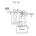
- FIG. 1A illustrates a schematic diagram of a fuel injection control apparatus.
- the mass of air flow Q a in the intake manifold of an engine is detected by a hot-wire air flow meter 2 and applied to a computer 1.
- the computer 1 receives the throttle position 8th from a throttle position sensor 3, the intake manifold pressure P from a manifold pressure sensor 4, the cooling water temperature T w from a water temperature sensor 5, the engine speed N from a crank angle sensor 6 and a binary signal indicative of a lean or rich mixture from an O2 sensor 7.
- the computer 1 directs the desired fuel injection quantity G f to an injector 8.
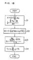
- the computer 1 calculates the rate of deposition of the fuel injection quantity on the intake manifold wall and the rate of vaporization of the film mass deposited on the intake manifold wall from the following equations (1) and (2), respectively, according to the inputted data. If the deposition rate is represented by X and the vaporization rate by 1/ T , the deposition rate X is simply given for example as a function of the throttle position 8th as follows
- the vaporization rate 1/ T is given as a function of the water temperature T w as follows
- the current film mass quantity is calculated from the film mass quantity obtained during the preceding cycle and the actually injected fuel quantity as follows where AT is the computing cycle period, M, is the film mass quantity, G, is the fuel injection quantity and G f ⁇ y is the actually injected fuel quantity in terms of the fuel quantity per unit time.
- the fuel injection quantity per unit time is determined in accordance with the deposition rate and the film mass quantity in the following manner.
- the fuel injection quantity of the engine must correspond to the intake air flow and therefore the desired value of the fuel quantity to be supplied to each cylinder is given as follows.
- Q a is the intake air flow
- (A/F) is the desired air-fuel ratio
- G fe * is the desired value of the quantity of fuel injected into the engine cylinder.
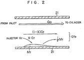
- Figure 2 shows the behavior within the intake manifold of the fuel quantity entering the engine cylinder.
- G f represents the injected fuel quantity
- X ⁇ G f represents the quantity of the fuel deposited on an intake manifold wall 21
- (1-X)G f represents the quantity of the fuel supplied to the cylinder without deposition.
- M/T represents the quantity of fuel supplied to the cylinder by the vaporization of the previously deposited fuel quantity (film mass quantity) on the intake manifold wall 21.
- the equation (7) is obtained as follows.
- the fuel quantity Q a /(A/F) to be supplied to the cylinder-to attain the desired air-fuel ratio is obtained in accordance with the intake air flow Q a and the fuel quantity 1/ T M f to be carried over to the cylinder is obtained in accordance with the vaporization rate 1/ T and the film mass quantity M f .
- the fuel quantity 1/ T M f is subtracted from the fuel quantity QJ(A/F) and the difference is divided by the non-deposition rate (1-X) of the injection fuel to be supplied to the cylinder without deposition thereby determining the desired fuel quantity per unit time.
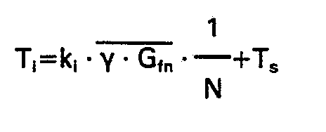
- the value of G, obtained at the step 103 is the fuel injection quantity per unit time, it is then converted to a fuel injection pulse width per stroke of the engine at a step 104, as follows where N is the engine speed, k l is a coefficient determined by the characteristics of the injector, y is the feedback correction factor derived from the 0 2 sensor signal and T s is a dead fuel injection time.
- the fuel injection pulse width per stroke T is renewed at intervals of the computing cycle and therefore the actual fuel injection takes place for the duration of the fuel injection pulse width T l existing at the time of arrival of an interrupt signal generated for every stroke. Therefore, as the fuel injection quantity data required for the computer to calculate the quantity of film mass during the next cycle, the actual fuel injection pulse width in terms of the following quantity corresponding to the fuel quantity per unit time is fed back
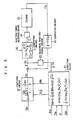
- FIG. 3 illustrates a block diagram of the fuel injection control system in the computer 1 of Figure 1A.
- a fuel injection quantity per unit time G f is calculated by computing means 12 in accordance with the film mass estimated by computing means 13 for estimating the film mass quantity M f deposited on the intake manifold wall and the mass of air flow.
- Computing means 11 calculates the quantity of fuel injected per stroke as shown by equation: where k i is a coefficient which is used in the conversion to the fuel injection quantity per stroke and dependent on the injector characteristics and T s is a dead injection time.
- the computing means 13 computes the quantity of film mass in the intake manifold in accordance with equation (3):
- the right member M fn represents the film mass quantity for the preceding cycle and the left member M fn+1 is the newly estimated film mass quantity.
- 1/ T represents the rate of vaporization of the film mass
- X represents the rate of fuel deposition on the intake manifold wall to the injected fuel quantity (referred to as a deposition rate).
- Represented by AT is one cycle period of the computation by the blocks of Figure 3.
- the following in the right member represents the quantity of fuel delivered to the cylinder by the vaporization of the film mass during one cycle period
- the fuel injection quantity per unit time y ⁇ G f resulting from the integration of the feedback correction factor y represents the quantity of fuel injected per unit time which is renewed in response to the application of a stroke start signal from the crank angle sensor.
- the deposition rate X and the vaporization rate 1/ T are obtained by experiments in accordance with the throttle position ⁇ th, the water temperature T w , the manifold pressure P, the mass air flow Q a , etc.
- the deposition rate X is given as a function of the throttle position for purposes of simplicity, as in equation (1):
- the occurrence of lean spikes during the engine acceleration and the occurrence of rich spikes during the engine deceleration are eliminated as compared with the conventional method in which a basic fuel injection quantity is determined in accordance with the flow of intake air.
- This has the effect of improving the engine performance during the acceleration and ensuring effective removal of the harmful gases during the deceleration.
- the desired acceleration and deceleration corrections can be provided by matching only the deposition rate of the fuel injection and the vaporization rate of the film mass in accordance with the acceleration and deceleration air-fuel ratios and thus the invention has the effect of providing more efficient manufacturing steps.
- the quantity of the film mass deposited on the intake manifold wall is estimated by newly estimating the film mass quantity by using the actually injected fuel quantity, it is possible to estimate an accurate film mass quantity closer to the actual film mass quantity.
- the air-fuel ratio of the mixture supplied to the engine can be controlled at around the stoichiometric air-fuel ratio even during the engine acceleration and deceleration.
- the invention has the effect of improving the exhaust gas purification and the engine performance.
Landscapes
- Engineering & Computer Science (AREA)
- Chemical & Material Sciences (AREA)
- Combustion & Propulsion (AREA)
- Mechanical Engineering (AREA)
- General Engineering & Computer Science (AREA)
- Electrical Control Of Air Or Fuel Supplied To Internal-Combustion Engine (AREA)
- Combined Controls Of Internal Combustion Engines (AREA)
Claims (4)


Applications Claiming Priority (2)
| Application Number | Priority Date | Filing Date | Title |
|---|---|---|---|
| JP59248127A JP2550014B2 (ja) | 1984-11-26 | 1984-11-26 | エンジンの燃料噴射制御方法 |
| JP248127/84 | 1984-11-26 |
Publications (3)
| Publication Number | Publication Date |
|---|---|
| EP0184626A2 EP0184626A2 (de) | 1986-06-18 |
| EP0184626A3 EP0184626A3 (en) | 1986-08-27 |
| EP0184626B1 true EP0184626B1 (de) | 1990-01-10 |
Family
ID=17173630
Family Applications (1)
| Application Number | Title | Priority Date | Filing Date |
|---|---|---|---|
| EP85112425A Expired - Lifetime EP0184626B1 (de) | 1984-11-26 | 1985-10-01 | Steuerverfahren für einen Motor mit Kraftstoffeinspritzung |
Country Status (4)
| Country | Link |
|---|---|
| EP (1) | EP0184626B1 (de) |
| JP (1) | JP2550014B2 (de) |
| KR (1) | KR930012226B1 (de) |
| DE (1) | DE3575331D1 (de) |
Families Citing this family (23)
| Publication number | Priority date | Publication date | Assignee | Title |
|---|---|---|---|---|
| DE3636810A1 (de) * | 1985-10-29 | 1987-04-30 | Nissan Motor | Kraftstoffeinspritzregelsystem fuer eine brennkraftmaschine |
| JPS63314339A (ja) * | 1987-06-17 | 1988-12-22 | Hitachi Ltd | 空燃比制御装置 |
| US4903668A (en) * | 1987-07-29 | 1990-02-27 | Toyota Jidosha Kabushiki Kaisha | Fuel injection system of an internal combustion engine |
| JPH01182552A (ja) * | 1988-01-18 | 1989-07-20 | Hitachi Ltd | 空燃比適応制御装置 |
| JP2941282B2 (ja) * | 1988-03-25 | 1999-08-25 | 株式会社日立製作所 | 燃料噴射制御方法および装置 |
| US4974563A (en) * | 1988-05-23 | 1990-12-04 | Toyota Jidosha Kabushiki Kaisha | Apparatus for estimating intake air amount |
| JP2512787B2 (ja) * | 1988-07-29 | 1996-07-03 | 株式会社日立製作所 | 内燃機関のスロットル開度制御装置 |
| JPH07116963B2 (ja) * | 1988-09-19 | 1995-12-18 | 株式会社日立製作所 | 空燃比の補正方法、及び、同補正装置 |
| JPH02227532A (ja) * | 1989-02-28 | 1990-09-10 | Fuji Heavy Ind Ltd | 燃料噴射制御装置 |
| WO1990012958A1 (de) * | 1989-04-26 | 1990-11-01 | Siemens Aktiengesellschaft | Vorrichtung für das einhalten eines vorgegebenen kraftstoff-luft-verhältnisses im verbrennungsraum eines kolbenmotors |
| JPH0323339A (ja) * | 1989-06-20 | 1991-01-31 | Mazda Motor Corp | エンジンの燃料制御装置 |
| JPH0392557A (ja) * | 1989-09-04 | 1991-04-17 | Hitachi Ltd | エンジンの燃料噴射制御方法 |
| JP2825920B2 (ja) * | 1990-03-23 | 1998-11-18 | 株式会社日立製作所 | 空燃比制御装置 |
| DE4040637C2 (de) * | 1990-12-19 | 2001-04-05 | Bosch Gmbh Robert | Elektronisches Steuersystem für die Kraftstoffzumessung bei einer Brennkraftmaschine |
| US5307276A (en) * | 1991-04-25 | 1994-04-26 | Hitachi, Ltd. | Learning control method for fuel injection control system of engine |
| CA2077068C (en) * | 1991-10-03 | 1997-03-25 | Ken Ogawa | Control system for internal combustion engines |
| US5383126A (en) * | 1991-10-24 | 1995-01-17 | Honda Giken Kogyo Kabushiki Kaisha | Control system for internal combustion engines with exhaust gas recirculation systems |
| US5261370A (en) * | 1992-01-09 | 1993-11-16 | Honda Giken Kogyo Kabushiki Kaisha | Control system for internal combustion engines |
| JPH05312072A (ja) * | 1992-05-07 | 1993-11-22 | Honda Motor Co Ltd | 内燃エンジンの空燃比制御装置 |
| DE4447868B4 (de) * | 1993-11-30 | 2004-04-22 | Honda Giken Kogyo K.K. | Kraftstoffeinspritzmengen-Steuersysstem für Verbrennungsmotoren und dabei benutzte Bestimmungseinrichtung für die Ansaugkanal-Wandtemperatur |
| CA2136908C (en) * | 1993-11-30 | 1998-08-25 | Toru Kitamura | Fuel injection amount control system for internal combustion engines and intake passage wall temperature-estimating device used therein |
| JPH07208249A (ja) * | 1994-01-12 | 1995-08-08 | Honda Motor Co Ltd | 内燃エンジンの制御装置 |
| FR2760045B1 (fr) * | 1997-02-25 | 1999-04-16 | Renault | Procede de regulation de la richesse d'un moteur thermique a injection indirecte |
Family Cites Families (4)
| Publication number | Priority date | Publication date | Assignee | Title |
|---|---|---|---|---|
| CA1154121A (en) * | 1979-09-27 | 1983-09-20 | Laszlo Hideg | Fuel metering system for an internal combustion engine |
| JPS588238A (ja) * | 1981-07-06 | 1983-01-18 | Toyota Motor Corp | 燃料噴射式エンジンの燃料噴射量制御方法 |
| US4667640A (en) * | 1984-02-01 | 1987-05-26 | Hitachi, Ltd. | Method for controlling fuel injection for engine |
| JPS60201042A (ja) * | 1984-03-27 | 1985-10-11 | Aisan Ind Co Ltd | エンジンの空燃比制御方法 |
-
1984
- 1984-11-26 JP JP59248127A patent/JP2550014B2/ja not_active Expired - Fee Related
-
1985
- 1985-09-30 KR KR1019850007221A patent/KR930012226B1/ko not_active IP Right Cessation
- 1985-10-01 DE DE8585112425T patent/DE3575331D1/de not_active Expired - Lifetime
- 1985-10-01 EP EP85112425A patent/EP0184626B1/de not_active Expired - Lifetime
Non-Patent Citations (1)
| Title |
|---|
| SAE-paper 810494 * |
Also Published As
| Publication number | Publication date |
|---|---|
| KR860004235A (ko) | 1986-06-18 |
| EP0184626A3 (en) | 1986-08-27 |
| DE3575331D1 (de) | 1990-02-15 |
| KR930012226B1 (ko) | 1993-12-24 |
| JP2550014B2 (ja) | 1996-10-30 |
| JPS61126337A (ja) | 1986-06-13 |
| EP0184626A2 (de) | 1986-06-18 |
Similar Documents
| Publication | Publication Date | Title |
|---|---|---|
| EP0184626B1 (de) | Steuerverfahren für einen Motor mit Kraftstoffeinspritzung | |
| US4939658A (en) | Control method for a fuel injection engine | |
| EP0069219B1 (de) | Verfahren und Vorrichtung zur Steuerung einer Brennkraftmaschine mit einer Brennstoffeinspritzanlage | |
| EP0286104B1 (de) | Verfahren zur Vorausberechnung der Parameter zur Steuerung der Kraftstoffzufuhr für eine Brennkraftmaschine | |
| US5282449A (en) | Method and system for engine control | |
| EP0301548B1 (de) | Kraftstoffeinspritzungssystem einer Brennkraftmaschine | |
| EP0536001B1 (de) | Steuerungssystem für Verbrennungsmotoren | |
| US4905653A (en) | Air-fuel ratio adaptive controlling apparatus for use in an internal combustion engine | |
| US4481928A (en) | L-Jetronic fuel injected engine control device and method smoothing air flow meter overshoot | |
| US4886030A (en) | Method of and system for controlling fuel injection rate in an internal combustion engine | |
| EP0352657B1 (de) | Verfahren und Einrichtung zum Regeln des Durchgangsgrades einer Drosselklappe in einem Verbrennungsmotor | |
| EP0735261A2 (de) | Motorsteuerung mit Kompensation der Luftdurchflussmesseinrichtung | |
| EP0134547B1 (de) | Verfahren um Kraftstoffeinspritzung in einen Motor zu steuern | |
| JPH0573908B2 (de) | ||
| EP0551207B1 (de) | Steuerungssystem für Innenverbrennungsmotoren | |
| KR0158880B1 (ko) | 엔진의 연료분사 제어방법 | |
| JP2564858B2 (ja) | 内燃機関の燃料噴射量制御装置 | |
| JP2548273B2 (ja) | 内燃機関の燃料噴射制御装置 | |
| JPH08312413A (ja) | エンジンの空燃比制御装置 | |
| EP0156356B1 (de) | Verfahren zur Steuerung der Kraftstoffzufuhr eines Innenverbrennungsmotors | |
| EP0335334B1 (de) | Brennstofförderungssteuersystem für Brennkraftmaschine mit verbesserten Beschleunigungsabläufen nach Beendigung einer Kraftstoffabsperrung | |
| JPS6318766Y2 (de) | ||
| JPS6161940A (ja) | 吸気管壁面液膜燃料量の推定方法 | |
| SU1719686A1 (ru) | Способ регулировани топливоподачи в двигатель внутреннего сгорани с впрыском бензина в впускной тракт | |
| JP2005069045A (ja) | 内燃機関の燃料噴射制御装置 |
Legal Events
| Date | Code | Title | Description |
|---|---|---|---|
| PUAI | Public reference made under article 153(3) epc to a published international application that has entered the european phase |
Free format text: ORIGINAL CODE: 0009012 |
|
| AK | Designated contracting states |
Kind code of ref document: A2 Designated state(s): DE GB |
|
| PUAL | Search report despatched |
Free format text: ORIGINAL CODE: 0009013 |
|
| AK | Designated contracting states |
Kind code of ref document: A3 Designated state(s): DE GB |
|
| 17P | Request for examination filed |
Effective date: 19870213 |
|
| 17Q | First examination report despatched |
Effective date: 19870723 |
|
| GRAA | (expected) grant |
Free format text: ORIGINAL CODE: 0009210 |
|
| AK | Designated contracting states |
Kind code of ref document: B1 Designated state(s): DE GB |
|
| REF | Corresponds to: |
Ref document number: 3575331 Country of ref document: DE Date of ref document: 19900215 |
|
| PLBI | Opposition filed |
Free format text: ORIGINAL CODE: 0009260 |
|
| 26 | Opposition filed |
Opponent name: ROBERT BOSCH GMBH Effective date: 19901010 |
|
| APAC | Appeal dossier modified |
Free format text: ORIGINAL CODE: EPIDOS NOAPO |
|
| PLBO | Opposition rejected |
Free format text: ORIGINAL CODE: EPIDOS REJO |
|
| PLBN | Opposition rejected |
Free format text: ORIGINAL CODE: 0009273 |
|
| STAA | Information on the status of an ep patent application or granted ep patent |
Free format text: STATUS: OPPOSITION REJECTED |
|
| APAU | Communication from the board of appeal sent |
Free format text: ORIGINAL CODE: EPIDOS OBAP |
|
| 27O | Opposition rejected |
Effective date: 19960217 |
|
| REG | Reference to a national code |
Ref country code: GB Ref legal event code: IF02 |
|
| PGFP | Annual fee paid to national office [announced via postgrant information from national office to epo] |
Ref country code: GB Payment date: 20030924 Year of fee payment: 19 |
|
| PGFP | Annual fee paid to national office [announced via postgrant information from national office to epo] |
Ref country code: DE Payment date: 20031203 Year of fee payment: 19 |
|
| PG25 | Lapsed in a contracting state [announced via postgrant information from national office to epo] |
Ref country code: GB Free format text: LAPSE BECAUSE OF NON-PAYMENT OF DUE FEES Effective date: 20041001 |
|
| PG25 | Lapsed in a contracting state [announced via postgrant information from national office to epo] |
Ref country code: DE Free format text: LAPSE BECAUSE OF NON-PAYMENT OF DUE FEES Effective date: 20050503 |
|
| GBPC | Gb: european patent ceased through non-payment of renewal fee |
Effective date: 20041001 |
|
| APAH | Appeal reference modified |
Free format text: ORIGINAL CODE: EPIDOSCREFNO |