EP0184584A2 - Kapazitive Längen- und Winkelmesseinrichtung - Google Patents
Kapazitive Längen- und Winkelmesseinrichtung Download PDFInfo
- Publication number
- EP0184584A2 EP0184584A2 EP84113309A EP84113309A EP0184584A2 EP 0184584 A2 EP0184584 A2 EP 0184584A2 EP 84113309 A EP84113309 A EP 84113309A EP 84113309 A EP84113309 A EP 84113309A EP 0184584 A2 EP0184584 A2 EP 0184584A2
- Authority
- EP
- European Patent Office
- Prior art keywords
- measuring device
- angle measuring
- capacitor
- electrodes
- capacitive
- Prior art date
- Legal status (The legal status is an assumption and is not a legal conclusion. Google has not performed a legal analysis and makes no representation as to the accuracy of the status listed.)
- Granted
Links
- 239000003990 capacitor Substances 0.000 claims abstract description 35
- 238000000576 coating method Methods 0.000 claims abstract description 11
- 230000005540 biological transmission Effects 0.000 claims description 23
- 238000006073 displacement reaction Methods 0.000 claims description 13
- 230000001105 regulatory effect Effects 0.000 claims description 3
- 238000013461 design Methods 0.000 abstract description 4
- 238000012886 linear function Methods 0.000 abstract description 3
- 238000010586 diagram Methods 0.000 description 8
- 230000010363 phase shift Effects 0.000 description 3
- 230000001419 dependent effect Effects 0.000 description 2
- 238000005562 fading Methods 0.000 description 2
- 230000008878 coupling Effects 0.000 description 1
- 238000010168 coupling process Methods 0.000 description 1
- 238000005859 coupling reaction Methods 0.000 description 1
- 238000011161 development Methods 0.000 description 1
- 230000018109 developmental process Effects 0.000 description 1
- 230000000694 effects Effects 0.000 description 1
- 238000011156 evaluation Methods 0.000 description 1
- 238000004519 manufacturing process Methods 0.000 description 1
- 238000005259 measurement Methods 0.000 description 1
- 238000000034 method Methods 0.000 description 1
- 230000008054 signal transmission Effects 0.000 description 1
- 230000001360 synchronised effect Effects 0.000 description 1
- 238000011144 upstream manufacturing Methods 0.000 description 1
Images


Classifications
-
- G—PHYSICS
- G01—MEASURING; TESTING
- G01B—MEASURING LENGTH, THICKNESS OR SIMILAR LINEAR DIMENSIONS; MEASURING ANGLES; MEASURING AREAS; MEASURING IRREGULARITIES OF SURFACES OR CONTOURS
- G01B7/00—Measuring arrangements characterised by the use of electric or magnetic techniques
- G01B7/30—Measuring arrangements characterised by the use of electric or magnetic techniques for measuring angles or tapers; for testing the alignment of axes
-
- G—PHYSICS
- G01—MEASURING; TESTING
- G01B—MEASURING LENGTH, THICKNESS OR SIMILAR LINEAR DIMENSIONS; MEASURING ANGLES; MEASURING AREAS; MEASURING IRREGULARITIES OF SURFACES OR CONTOURS
- G01B7/00—Measuring arrangements characterised by the use of electric or magnetic techniques
- G01B7/02—Measuring arrangements characterised by the use of electric or magnetic techniques for measuring length, width or thickness
-
- G—PHYSICS
- G01—MEASURING; TESTING
- G01D—MEASURING NOT SPECIALLY ADAPTED FOR A SPECIFIC VARIABLE; ARRANGEMENTS FOR MEASURING TWO OR MORE VARIABLES NOT COVERED IN A SINGLE OTHER SUBCLASS; TARIFF METERING APPARATUS; MEASURING OR TESTING NOT OTHERWISE PROVIDED FOR
- G01D5/00—Mechanical means for transferring the output of a sensing member; Means for converting the output of a sensing member to another variable where the form or nature of the sensing member does not constrain the means for converting; Transducers not specially adapted for a specific variable
- G01D5/12—Mechanical means for transferring the output of a sensing member; Means for converting the output of a sensing member to another variable where the form or nature of the sensing member does not constrain the means for converting; Transducers not specially adapted for a specific variable using electric or magnetic means
- G01D5/14—Mechanical means for transferring the output of a sensing member; Means for converting the output of a sensing member to another variable where the form or nature of the sensing member does not constrain the means for converting; Transducers not specially adapted for a specific variable using electric or magnetic means influencing the magnitude of a current or voltage
- G01D5/24—Mechanical means for transferring the output of a sensing member; Means for converting the output of a sensing member to another variable where the form or nature of the sensing member does not constrain the means for converting; Transducers not specially adapted for a specific variable using electric or magnetic means influencing the magnitude of a current or voltage by varying capacitance
- G01D5/241—Mechanical means for transferring the output of a sensing member; Means for converting the output of a sensing member to another variable where the form or nature of the sensing member does not constrain the means for converting; Transducers not specially adapted for a specific variable using electric or magnetic means influencing the magnitude of a current or voltage by varying capacitance by relative movement of capacitor electrodes
- G01D5/2412—Mechanical means for transferring the output of a sensing member; Means for converting the output of a sensing member to another variable where the form or nature of the sensing member does not constrain the means for converting; Transducers not specially adapted for a specific variable using electric or magnetic means influencing the magnitude of a current or voltage by varying capacitance by relative movement of capacitor electrodes by varying overlap
- G01D5/2415—Mechanical means for transferring the output of a sensing member; Means for converting the output of a sensing member to another variable where the form or nature of the sensing member does not constrain the means for converting; Transducers not specially adapted for a specific variable using electric or magnetic means influencing the magnitude of a current or voltage by varying capacitance by relative movement of capacitor electrodes by varying overlap adapted for encoders
Definitions
- the invention relates to a capacitive length and / or angle measuring device, the transducer of which consists of a stationary part and a part which can be displaced parallel over its surface at a small distance, the opposite surfaces of the stationary and the displaceable part being provided with capacitor coatings.
- Capacitive transducers are already known which are designed as differential capacitors. In practice, however, difficulties arise particularly when measuring longer lengths with such known differential capacitors. In order to eliminate such difficulties, several differential capacitors are arranged one after the other in a capacitive length measuring device in accordance with CH-PS 539 837. If the measuring range of a differential capacitor is exceeded during the shift, the next following differential capacitor lying in the direction of shift must be connected to the electronic circuit device by means of complex circuitry. The position information in this system is contained in the amplitude of the supply voltages of the differential capacitor.
- a measuring device for capacitive determination of the relative positions of two mutually movable parts which consist essentially of a slider and a scale.
- the phase angle Phi of the receiver voltage is a linear function of the displacement of the slider relative to the scale, if the transmission voltages are sinusoidal.
- a disadvantage here is that the amplitude of the receiver signal is small due to the small area of coverage between the transmitter and scale electrodes.
- Another disadvantage is that the scale electrodes are semi-sinusoidal and are therefore difficult to manufacture with the required precision.
- the stationary part formed as a scale from two rows of T-shaped, comb-like interlocking.
- capacitor coatings and the capacitor coatings of the displaceable part of the transducer act partly as transmitting electrodes and partly as receiving electrodes, the transmitting electrodes being fed with alternating voltage in such a way that an electric rotating field is generated which generates alternating voltages at the receiving electrodes, and that the phase relationship from the transmitting signal to the received signal the displacement between the stationary part and the displaceable part of the sensor is proportional.
- the two rows of capacitor linings of the stationary part can be shifted in the longitudinal direction by half a scale period from each other.
- the displaceable part of the measuring sensor can represent a plate-shaped scanning unit, on which rectangular capacitor coverings are arranged symmetrically with respect to the longitudinal axis of the plate.
- a transversely arranged capacitor covering as the receiving electrode can run at a distance such that the transmitting and receiving electrodes are arranged perpendicular to one another on the end faces of the capacitor coverings forming the transmitter electrodes.
- Such a design of a capacitive length and angle measuring device allows large areas of the capacitor coatings and thus a good capacitive coupling.
- the symmetrical arrangement of the capacitor linings also compensates for undesired changes in capacitance, for example due to fluctuations in the air gap.
- the received signals are fed to a differential amplifier.
- the mechanical variable to be measured causes a change in the area of a capacitor, the resulting change in capacitance acting as a variable, capacitive reactance in a circuit which changes the phase position of the electrical signals.
- a linear function is obtained between the mechanical quantity to be measured and the phase position of the signals.
- only the displaceable scanning unit can be connected to an electronic circuit device, while the stationary part has no electrical connection.
- the transmitting electrodes can be fed with sinusoidal AC voltages derived from square wave signals, and the received signals can be fed to a differential amplifier, the output signal of which is digitized by a zero crossing detector.
- the digitized Aufrehmer signal can be fed to a control circuit so that the phase difference between the pickup signal and the reference signal is regulated to zero and the phase difference is evaluated digitally, the phase difference containing the position information to be measured.
- An optimal and error-free effect is achieved according to further developments of the invention in that three adjacent capacitor coverings of the displaceable part form a transmission group form, and that on the movable part at least, two transmission groups are arranged side by side.
- the receiving electrodes can extend perpendicular to and across all transmission groups.
- the stationary part can be a round bar on which a cylindrical part can be axially displaced as a scanning unit.
- the stationary part can, however, also be a preferably circular disk, to which a disk arranged in parallel can be rotated around its central axis as a scanning unit, thereby realizing an angle measuring device.
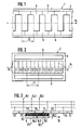
- the transducer of the length and angle measuring device essentially consists of a stationary part 1, which forms the scale, and the displaceable part 2, which represents the scanning unit.
- the displaceable part 2 is mounted at a short distance above the stationary part 1 and can be displaced parallel to it.
- the opposing surfaces 3 and 4 are provided with capacitor coatings 5, 6, 7, 8 and 9.
- the pads 5 and 6 of the stationary part 1 are T-shaped and applied to the part 1 in such a way that there are two rows of pads that intermesh like a comb.
- the pads 5 and 6 of the stationary part 1 and the scale are not electrically connected. They are scanned by the movable part 2 without contact.
- the capacitor coatings 7 of the displaceable part 2 of the transducer are designed as rectangular coverings and are arranged symmetrically on the part 2 directly next to one another. They have the function of transmitting electrodes.
- the capacitor coatings 8 and 9, which have the function of receiving electrodes, are located on both ends of the coatings 7 at 90 across the transmission electrodes. As can be seen from FIG. 2, the receiving electrodes 8 and 9 extend over the entire arrangement of the transmitting electrodes 7.
- the transmitting electrodes 7 are fed with alternating voltage in such a way that an electrical rotating field is generated which generates alternating voltages at the receiving electrodes 8, 9, the phase position of which depends on the position of the displaceable part 2 relative to the stationary part 1.
- the capacitive transducer is inserted into a digital system, which generates the transmit signals and evaluates the received signals.
- the two rows of interlocking capacitor linings 5 and 6 are shifted in accordance with FIG. 1 in the longitudinal direction 10 by half a scale period to one another.
- Three adjacent coverings 7.1, 7.2, and 7.3 of the scanning unit 2 each form a transmission group 11.
- several transmission groups 11 are arranged side by side on part 2.
- the width of a transmission group 11 corresponds to the width 12 of two adjacent webs of the T-shaped coverings 5 and 6 of the stationary part 1.
- the signals transmitted by the transmitting electrodes 7 of part 2 to scale 1 are fed back to the receiving electrodes 8, 9 of the scanning unit 2 through the coverings 5, 6.
- the simultaneous scanning of several transmission groups 11 reduces the influence of random errors in the scale division.
- the receiving electrodes 8, 9 of the scanning unit 2 according to the invention with respect to the coatings 5, 6 of the scale 1, a phase offset of the two received signals from one another of half a scale period is achieved.
- the transmitting electrodes 7 and the receiving electrodes 8, 9 must be electrically isolated from one another by a grounded screen 13.
- the electrical connection of the transmitting electrodes 7 and the receiving electrodes 8, 9 to the electronic circuit device according to FIG. 8 takes place via the rear of the displaceable part 2.
- each transmission group 11 The pads 7.1, 7.2, 7.3 of each transmission group 11 are three each 120 0 phase-shifted, sinusoidal AC voltages 15.1, 15.2 and 15.3 of the same amplitude and frequency from the relationship fed.
- the transmission voltages are superimposed in accordance with the variable partial capacitances 16.1, 16.2 and 16.3, which are dependent on the position of the scanning unit 2 relative to the scale 1.
- the voltages 17.1 and 17.2 resulting at the receiving electrodes are again sinusoidal AC voltages with the same frequency as the transmission voltages 15.1, 15.2 and 15.3. They have a phase angle Phi with respect to the transmission voltage 15.1, which is dependent on the position between the scale 1 and the scanning unit 2 according to the designation: '
- the amplitude depends on the value of the partial capacities.
- FIGS. 4 and 5 show the vector diagrams with the peak values for the position of the sensor shown in FIG. 3.
- phase angle Phi 18.1 between the received signal voltage 17.1 4 is proportional to the displacement 19 between the scale 1 and the scanning unit 2.
- the peak values depend on the value of the partial capacities 16.1, 16.2, 16.3.
- the characters w and x in FIGS. 4 and 5 mean w for angular displacement and x for displacement.
- FIG. 6 shows the locus of the receiver voltages 17.1. It can be seen that the amplitudes of the voltages receiver 17 .1 periodically by the value 3 0 fluctuate, as evidenced by the progress of the partial capacitances 16.1, 16.2, 16.3 is caused and from Fig. 7. The dependence between the displacement 19 and the course of the partial capacitances 16.1, 16.2 and 16.3 is illustrated for the receiver voltage 17.1 in FIG. 7.
- the displacement position X corresponds to the position of the transducer shown in FIG. 3.
- the partial capacitances 16.1, 16.2 and 16.3 each represent themselves as a function of the displacement path 19.
- a purely sinusoidal curve of the partial capacitances would be ideal here, which leads to a constant amplitude curve of the receiver voltage 17.1.
- a complicated geometry of the capacitor linings would be necessary.
- phase angle error when moving around a scale period of the phase angle error of the receiver voltages T f 1, 1 0 .This corresponds to an uncertainty of the displacement 19 of ⁇ 0.0092 mm. This phase angle error is largely compensated for by linking the two received signals 17.1 and 17.2 in the electronic circuit device.
- FIG. 8 shows the block diagram for the electronic circuit device for digitally measuring a displacement or an angle of rotation.
- the capacitive sensor is inserted in a digital system.
- the transducer is supplied with three 120-phase alternating voltages, preferably sinusoidal voltages, which are generated in the transmission voltage generating unit 20 from square wave signals according to known methods.
- digital signals that only contain higher order harmonics.
- Such harmonics are transmitted into the output signal of the sensor, but they can be eliminated with a filter 21 which is connected upstream of the zero crossing detector 22. This results in a rectangular pick-up signal, the phase position of which with respect to the digital, same-frequency reference signal that is generated in the reference divider 23 contains the information of the mechanical quantity to be measured.
- the phase evaluation takes place in a control loop in that the reference signal is continuously synchronized with the pickup signal in the synchronization stage 25.
- a pulse is generated by a phase comparison 24 of the two signals, the pulse width of which is proportional to the phase shift.
- This pulse controls the synchronization stage 25, which synchronizes the reference divider 23 to the pickup signal by fading in or fading out pulses. This means that the phase shift is regulated to zero.
- a gate 26 for the clock frequency of a counter 27 is controlled by the pulse generated during the phase comparison. The entire system is controlled by a clock which is supplied by a quartz-stable oscillator 28.
- the count result is equal to the value of the mechanical variable to be measured.
- a frequency divider 29 is connected downstream of the oscillator 28. The further course of the frequency divider 29 is via the transmission voltage generation 20 to a capacitive pick-up 42 to the differential amplifier 43.
- 31 denotes the display and 32 denotes a microcomputer to which the counter 27 is connected.
- FIG. 9 shows a length measuring system which is formed from the scale 33 and the scanning unit 34.
- the scanning unit 34 can be moved parallel to the scale in the direction of arrow 35.
- FIG. 10 Another type of length measuring system is shown in FIG. 10.
- the scale 36 is designed as a round rod, over which a hollow cylindrical scanning unit 37 can be displaced axially in the direction of the arrow 38.
- FIG. 11 An angle measuring device is shown in FIG. 11.
- the stationary part 39 as a scale is designed in the form of a circular disk.
- a further disk 40 Arranged parallel to this circular disk 39 is a further disk 40, which represents the scanning unit and can be displaced about its central axis in the direction of arrow 41.
Landscapes
- Physics & Mathematics (AREA)
- General Physics & Mathematics (AREA)
- Engineering & Computer Science (AREA)
- Power Engineering (AREA)
- Measurement Of Length, Angles, Or The Like Using Electric Or Magnetic Means (AREA)
- Transmission And Conversion Of Sensor Element Output (AREA)
Abstract
Description
- Die Erfindung betrifft eine kapazitive Längen- und/oder Winkelmeßeinrichtung, deren Meßwertaufnehmer aus einem stationären Teil und einem parallel über dessen Oberfläche im geringen Abstand verschiebbaren Teil besteht, wobei die einander gegenüberliegenden Oberflächen des stationären und des verschiebbaren Teils mit Kondensatorbelägen versehen sind.
- Es sind bereits kapazitive Meßwertaufnehmer bekannt, die als Differentialkondensatoren ausgebildet sind. In der Praxis ergeben sich aber insbesondere beim Messen größerer Längen mit solchen bekannten Differentialkondensatoren Schwierigkeiten. Um solche Schuierigkeiten zu beseitigen, werden entsprechend der CH-PS 539 837 bei einer kapazitiven Längenmeßeinrichtung mehrere Differentialkondensatoren hintereinander angeordnet. Wird bei der Verschiebung der Meßbereich eines Differentialkondensators überschritten, so muß durch aufwendige schaltungstechnische Mittel der nächstfolgende in Verschieberichtung liegende Differentialkondensator an die elektronische Schaltungseinrichtung geschaltet werden. Die Lageinformation ist bei diesem System in der Amplitude der Speisespannungen des Differentialkondensators enthalten.
- Aus der DE-OS 28 53 142 ist ferner eine Meßvorrichtung zur kapazitiven Bestimmung der relativen Lagen zweier zueinander beweglicher Teile bekannt, die im wesentlichen aus einem Gleitstück und einer Skala bestehen. Der Phasenwinkel Phi der Empfängerspannung ist eine lineare Funktion der Verschiebung des Gleitstücks gegenüber der Skala, wenn die Sendespannungen Sinusform besitzen.
- Ein Nachteil dabei ist, daß durch die geringe Überdeckungsfläche zwischen Sende- und Skalenelektroden die Amplitude des Empfängersignals klein ist. Ferner ist von Nachteil, daß die Skalenelektroden halbsinusförmig geformt sind und deshalb nur schwer mit der erforderlichen Präzision herstellbar sind.
- Es ist deshalb Aufgabe der Erfindung, eine kapazitive Längen- und/oder Winkelmeßeinrichtung der eingangs genannten Art zu schaffen, welche die vorerwähnten Nachteile vermeidet und es ermöglicht, mit wenig Hardwareaufwand ein Meßsystem mit geringem Energiebedarf zu realisieren.
- Diese Aufgabe wird erfindungsgemäß dadurch gelöst, daß der als Maßstab ausgebildete stationäre Teil aus zwei Reihen T-förmiger, kammartig ineinandergreifender . Kondensatorbeläge besteht, und die Kondensatorbeläge des verschiebbaren Teils des Meßwertaufnehmers teilweise als Sendeelektroden und teilweise als Empfangselektroden wirken, wobei die Sendeelektroden mit Wechselspannung derart gespeist sind, daß ein elektrisches Drehfeld entsteht, welches an den Empfangselektroden Wechselspannungen erzeugt, und daß die Phasenlage vom Sendesignal zum Empfangssignal proportional ist der Verschiebung zwischen dem stationären Teil und dem verschiebbaren Teil des Meßwertaufnehmers. Die zwei Reihen Kondensatorbeläge des stationären Teils können dabei in Längsrichtung um jeweils eine halbe Maßstabsperiode zueinander verschoben sein. Der verschiebbare Teil des Meßaufnehmers kann eine plattenförmige Abtasteinheit darstellen, auf welcher bezüglich der Plattenlängsachse rechteckförmige Kondensatorbeläge symmetrisch angeordnet sind. Dabei kann an den Stirnseiten der die Sendeelektroden bildenden Kondensatorbeläge jeweils ein quer angeordneter Kondensatorbelag als Empfangselektrode im Abstand dergestalt verlaufen, daß Sende- und Empfangselektroden senkrecht zueinander angeordnet sind.
- Eine solche Ausbildung einer kapazitiven Längen- und Winkelmeßeinrichtung erlaubt große Flächeninhalte der Kondensatorbeläge und damit eine gute kapazitive Kopplung. Durch die symmetrische Anordnung der Kondensatorbeläge werden ferner unerwünschte Kapazitätsänderungen bspw. durch Luftspaltschwankungen kompensiert. Die Empfangssignale werden einem Differenzverstärker zugeführt.
- Nach dem erfindungsgemäßen Prinzip des kapazitiven Meßwertaufnehmers bewirkt die zu messende mechanische Größe eine Flächenänderung eines Kondensators, wobei die dadurch entstehende Kapazitätsänderung als ein veränderlicher, kapazitiver Blindwiderstand in einem Stromkreis wirkt, der die Phasenlage der elektrischen Signale ändert. Bei der erfindungsgemäßen Gestaltung der Kondensatorflächen erhält man eine lineare Funktion zwischen der zu messenden mechanischen Größe und der Phasenlage der Signale.
- In weiterer Ausbildung der Erfindung kann nur die verschiebbare Abtasteinheit an eine elektronische Schaltungpeinrichtung angeschlossen sein, während der stationäre Teil keinen elektrischen Anschluß aufweist.
- Die Sendeelektroden können mit sinusförmigen Wechselspannungen gespeist sein, die von Rechtecksignalen abgeleitet sind, und die Empfangssignale können einem Differenzverstärker zugeführt werden, dessen Ausgangssignal durch einen Nulldurchgangsdetektor digitalisiert wird.
- Dabei kann fernerhin das digitalisierte Aufrehmersignal einen Regelkreis so zugeführt sein, daß die Phasendifferenz zwischen dem Aufnehmersignal und dem Referenzsignal zu Null geregelt und die Phasendifferenz digital ausgewertet wird, wobei die Phasendifferenz die zu messende Lageinformation enthält.
- Eine optimale und fehlerfreie Wirkung wird gemäß weiterer Ausbildungen der Erfindung dadurch erzielt, daß jeweils drei nebeneinanderliegende Kondensatorbeläge des verschiebbaren Teils eine Sendegruppe bilden, und daß auf dem verschiebbaren Teil zumindest, zwei Sendegruppen nebeneinander angeordnet sind. die Empfangselektroden können sich jeweils senkrecht zu und über alle Sendegruppen erstrecken.
- Vorteilhaft ist weiterhin, die Sendeelektroden und Empfangselektroden durch einen geerdeten Schirm voneinander elektrisch zu isolieren.
- Nach den weiteren Vorschlägen der Erfindung kann der stationäre Teil ein Rundstab sein, auf dem ein zylinderförmiger Teil als Abtasteinheit axial verschiebbar ist. Der stationäre Teil kann aber auch eine vorzugsweise kreisförmige Scheibe sein, zu der im Abstand eine parallel angeordnete Scheibe als Abtasteinheit um ihre Mittelachse drehbar ist, wodurch eine Winkelmeßeinrichtung realisiert wird.
- In der Zeichnung ist ein Beispiel der Erfindung dargestellt. Es zeigen: i
- Fig. 1 den stationären Teil des Meßwertaufnehmers;
- Fig. 2 den verschiebbaren Teil des Meßwertaufnehmers;
- Fig. 3 Schaltbild der mit phasenverschobenen Wechselspannungen gespeisten Sendegruppen;
- Fig. 4 Zeigerdiagramm für erstes Sendesignal;
- Fig. 5 Zeigerdiagramm für phasenverschobenes zweites Sendesignal;
- Fig. 6 schematische Darstellung der Ortskurve einer EmpfängeTspannung;
- Fig. 7 Diagramm über den Verlauf von Teilkapazitäten;
- Fig. 8 Blockschaltbild der elektronischen Schaltungseinrichtung;
- Fig. 9 Ausführungsform einer Längenmeßeinrichtung in vereinfachter perspektivischer Darstellung;
- Fig. 10 eine andere Ausführung einer Längenmeßeinrichtung in vereinfachter Perspektive;
- Fig. 11 Ausführungsform einer Winkelmeßeinrichtung in vereinfachter perspektivischer Darstellung.
- Der Meßwertaufnehmer der erfindungsgemäßen Längen- und Winkelmeßeinrichtung besteht im wesentlichen aus einem stationären Teil 1, welcher den Maßstab bildet, und dem verschiebbaren Teil 2, der die Abtasteinheit darstellt. Der verschiebbare Teil 2 ist im geringen Abstand über dem stationären Teil 1 gelagert und parallel zu diesem verschiebbar. Die einander gegenüberliegenden Flächen 3 und 4 sind mit Kondensatorbelägen 5, 6, 7, 8 und 9 versehen. Die Beläge 5 und 6 des stationären Teils 1 sind T-förmig ausgebildet und derart auf den Teil 1 aufgetragen, daß sich zwei Reihen von Belägen ergeben, die kammartig ineinandergreifen. Die Beläge 5 und 6 des stationären Teils 1 bzw. des Maß- stabs sind elektrisch nicht angeschlossen. Sie werden von dem verschiebbaren Teil 2 berührungslos abgetastet. Die Kondensatorbeläge 7 des verschiebbaren Teils 2 des Meßwertaufnehmers sind als rechteckförmige Beläge ausgeführt und direkt nebeneinanderliegend symmetrisch auf dem Teil 2 angeordnet. Sie besitzen die Funktion von Sendeelektroden. Um 90 quer zu den Sendeelektroden befinden sich zu beiden Stirnseiten der Beläge 7 die Kondensatorbeläge 8 und 9, welche die Funktion von Empfangselektroden haben. Wie aus Fig. 2 ersichtlich ist, erstrecken sich die Empfangselektroden 8 und 9 über die gesamte Anordnung der Sendeelektroden 7.
- Die Sendeelektroden 7 werden derart mit Wechselspannung gespeist, daß ein elektrisches Drehfeld entsteht, das an den Empfangselektroden 8, 9 Wechselspannungen erzeugt, deren Phasenlage von der Stellung des verschiebbaren Teils 2 zum stationären Teil 1 abhängig ist. Zur digitalen Messung einer Länge oder eines Winkels wird der kapazitive Meßwertaufnehmer in ein digitales System eingefügt, das die Sendesignale erzeugt und die Empfangssignale auswertet.
- Die zwei Reihen ineinandergreifender Kondensatorbeläge 5 und 6 sind gemäß Fig. 1 in Längsrichtung 10 um eine halbe Maßstabsperiode zueinander verschoben. Jeweils drei nebeneinanderliegende Beläge 7.1, 7.2, und 7.3 der Abtasteinheit 2 bilden eine Sendegruppe 11. Dazu sind mehrere Sendegruppen 11 auf dem Teil 2 nebeneinander angeordnet. Die Breite einer Sendegruppe 11 entspricht der Breite 12 von zwei nebeneinanderliegenden Stegen der T-förmigen Beläge 5 und 6 des stationären Teiles 1.
- Die von den Sendeelektroden 7 des Teils 2 auf den Maßstab 1 gesendeten Signale werden durch die Beläge 5, 6 auf die Empfangselektroden 8, 9 der Abtasteinheit 2 zurückgekoppelt. Durch die gleichzeitige Abtastung mehrerer Sendegruppen 11 wird der Einfluß von zufälligen Fehlern der Maßstabsteilung vermindert. Durch die erfindungsgemäße Anordnung der Empfangselektroden 8, 9 der Abtasteinheit 2 gegenüber den Belägen 5, 6 des Maßstabs 1 erreicht man einen Phasenversatz der beiden Empfangssignale zueinander von einer halben Maßstabsperiode. Um ein direktes Übersprechen vom Sender zum Empfänger in der Abtasteinheit zu verhindern, müssen die Sendeelektroden 7 und die Empfangselektroden 8,9 durch einen geerdeten Schirm 13 voneinander elektrisch isoliert werden.
- Die symmetrische Anordnung der Beläge 7, 8, 9 der Abtasteinheit 2 bezüglich der Verschiebeachse 14 und die Verstärkung der beiden um 1800 phasenverschobenen Empfangssignale mit einem Differenzverstärker bewirken eine Signalverdopplung und eine weitgehende Kompensation der Fehlersignale, die durch Verkippen um die Verschiebeachse 14 hervorgerufen sein können.
- Der elektrische Anschluß der Sendeelektroden 7 und der Empfangselektroden 8, 9 an die elektronische Schaltungseinrichtung gemäß Fig. 8 erfolgt über die Rückseite des verschiebbaren Teils 2.
- Die Beläge 7.1, 7.2, 7.3 jeder Sendegruppe 11 werden mit drei um jeweils 1200 phasenverschobenen, sinusförmigen Wechselspannungen 15.1, 15.2 und 15.3 gleicher Amplitude und gleicher Frequenz aus der Beziehung


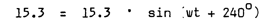
- An den Empfangselektroden 8 und 9 erfolgt eine Überlagerung der Sendespannungen entsprechend den variablen Teilkapazitäten 16.1, 16.2 und 16.3, die von der Position der Abtasteinheit 2 gegenüber dem Maßstab 1 abhängig sind. Die an den Empfangselektroden resultierenden Spannungen 17.1 und 17.2 sind wiederum sinusförmige Wechselspannungen mit gleicher Frequenz wie die Sendespannungen 15.1, 15.2 und 15.3. Sie besitzen eine Phasenlage Phi bezüglich der Sendespannung 15.1, die abhängig ist von der Position zwischen dem Maßstab 1 und der Abtasteinheit 2 nach der Bezeichnung: '


- Daraus folgt:

- Die Amplitude ist abhängig vom Wert der Teilkapazitäten.
- Die Anordnung der Kondensatorbeläge 5, 6, 7, 8, 9 auf dem Maßstab 1 und der Abtasteinheit 2 bewirkt, daß immer zwei oder drei Sendespannungen an der Signalübertragung beteiligt sind. Durch das Zeigerdiagramm in den Figuren 4 und 5 lassen sich die Überlagerung der Sendespannungen und die resultierenden Empfängerspannungen anschaulich darstellen. In den Figuren 4 und 5 sind die Zeigerdiagramme mit den Scheitelwerten für die in der Fig. 3 dargestellten Position des Meßwertaufnehmers gezeigt.
- Der Phasenwinkel Phi 18.1 zwischen dem Empfangssignal Spannung 17.1 und dem Sendesignal Spannung 15.1 gemäß Fig. 4 ist proportional der Verschiebung 19 zwischen dem Maßstab 1 und der Abtasteinheit 2. Das gleiche trifft für den Phasenwinkel Phi 18.2 zwischen dem Empfangssignal Spannung 17.2 und dem Sendesignal Spannung 15.1 zu. Die Scheitelwerte sind abhängig vom Wert der Teilkapazitäten 16.1, 16.2, 16.3. Die Zeichen w und x in den Figuren 4 und 5 bedeuten w für Drehwinkelverschiebung und x für Wegeverschiebung.
- In der Fig. 6 ist die Ortskurve der Empfängerspannungen 17.1 dargestellt. Es ist ersichtlich, daß die Amplituden der Empfängerspannungen 17.1 periodisch um den Wert 30 schwanken, was durch den Verlauf der Teilkapazitäten 16.1, 16.2, 16.3 bedingt ist und aus Fig. 7 hervorgeht. Die Abhängigkeit zwischen der Verschiebung 19 und dem Verlauf der Teilkapazitäten 16.1, 16.2 und 16.3 ist für die Empfängerspannung 17.1 in Fig. 7 veranschaulicht.
- Die Verschiebeposition X entspricht der in Fig. 3 gezeigten Position des Meßwertaufnehmers. Die Teilkapazitäten 16.1, 16.2 und 16.3 stellen sich jeweils als Funktion des Verschiebeweges 19 dar. Ideal wäre hier ein rein sinusförmiger Verlauf der Teilkapazitäten, was zu einem konstanten Amplitudenverlauf der Empfängerspannung 17.1 führt. Um dies zu erreichen, wäre allerdings eine komplizierte Geometrie der Kondensatorbeläge notwendig. Bei dem Verschieben der Abtasteinheit 2 um eine Maßstabsperiode T,die dem Wert 12 in Fig. 1 bzw. 11 in Fig. 2 entspricht, ergibt sich eine Phasenverschiebung von Phi 18.1 um 360°. Wird bspw.eine Maßstabsperiode von T = 3 mm verwendet, so beträgt bei der Gestaltung des Meßwertaufnehmers nach den Fig. 1 und 2 beim Verschieben um eine Maßstabsperiode T der Phasenwinkelfehler der Empfängerspannungen f 1, 1 0.Dies entspricht einer Meßunsicherheit der Verschiebung 19 von ± 0,0092 mm. Dieser Phasenwinkelfehler wird weitgehend durch die Verknüpfung der beiden Empfangssignale 17.1 und 17.2 in der elektronischen Schaltungseinrichtung kompensiert.
- In Fig. 8 ist das Blockschaltbild für die elektronische Schaltungseinrichtung zur digitalen Messung einer Verschiebung oder eines Drehwinkels gezeigt.
- Der kapazitive Meßwertaufnehmer ist in ein digitales System eingefügt. Die Speisung des Meßwertaufnehmers erfolgt mit drei um 120 phasenverschobenen Wechselspannungen, vorzugsweise sinusförmige Spannungen, die in der Sendespannungserzeugungseinheit 20 nach bekannten Methoden aus Rechtecksignalen erzeugt werden. Möglich ist natürlich auch eine Speisung mit digitalen Signalen, die nur Oberwellen höherer Ordnung enthalten. Solche Oberwellen werden zwar in das Ausgangssignal des Meßwertaufnehmers übertragen, sie können aber mit einem Filter 21, das vor den Nulldurchgangsdetektor 22 geschaltet ist, beseitigt werden. Es entsteht hierdurch ein rechteckförmiges Aufnehmersignal, dessen Phasenlage bezüglich des digitalen, gleichfrequenten Referenzsignals, das im Referenzteiler 23 erzeugt wird, die Informationen der zu messenden, mechanischen Größe enthält. Die Phasenauswertung erfolgt in einem Regelkreis, indem das Referenzsignal fortlaufend auf das Aufnehmersignal in der Synchronisationsstufe 25 synchronisiert wird. Durch einen Phasenvergleich 24 der beiden Signale,wird ein Impuls erzeugt, dessen Pulsbreite proportinoal der Phasenverschiebung ist. Dieser Puls steuert einmal die Synchronisationsstufe 25, die durch Einblenden oder Ausblenden von Impulsen den Referenzteiler 23 auf das Aufnehmersignal synchronisiert. Dies bedeutet, daß die Phasenverschiebung auf Null geregelt wird. Andererseits wird durch den beim Phasenvergleich generierten Impuls ein Tor 26 für die Taktfrequenz eines Zählers 27 gesteuert. Das Gesamtsystem wird von einem Takt gesteuert, den ein quarzstabiler Oszillator 28 liefert.
- Bei einer entsprechenden Zuordnung der Taktfrequenzen und Steuersignale im System ist das Zählergebnis gleich dem Wert der zu messenden mechanischen Größe.
- Dem Oszillator 28 nachgeschaltet ist ein Frequenzteiler 29. Vom Frequenzteiler 29 ist der weitere Verlauf über die Sendespannungserzeugung 20 einem kapazitiven Aufnehmer 42 zum Differenzverstärker 43. Mit 31 ist die Anzeige und mit 32-ein Mikrocomputer bezeichnet, an den der Zähler 27 angeschlossen ist.
- Figur 9 zeigt ein Längenmeßsystem, welches aus dem Maßstab 33 und der Abtasteinheit 34. gebildet ist. Die Abtasteinheit 34 ist parallel zum Maßstab in Pfeilrichtung 35 verschiebbar.
- Eine andere Art eines Längenmeßsystems zeigt Fig. 10. Der Maßstab 36 ist als Rundstab ausgeführt, über den eine hohlzylindrische Abtasteinheit 37 axial verschiebbar ist gemäß der Pfeilrichtung 38.
- Eine Winkelmeßeinrichtung ist in Fig. 11 dargestellt. Der stationäre Teil 39 als Maßstab ist in Form einer Kreisscheibe ausgebildet. Parallel zu dieser Kreisscheibe 39 ist eine weitere Scheibe 40 angeordnet, die die Abtasteinheit darstellt und um ihre Mittelachse in der Pfeilrichtung 41 verschiebbar ist.
Claims (11)
daß der als Maßstab ausgebildete stationäre Teil (1, 33, 36, 39) aus zwei Reihen T-förmiger, kammartig ineinandergreifender Kondensatorbeläge (5, 6) besteht, und die Kondensatorbeläge (7, 8, 9) des verschiebbaren Teils (2, 34, 37, 40) des Meßwertaufnehmers teilweise als Sendeelektroden (7.1, 7.2, 7.3) und teilweise als Empfangselektroden (8, 9) wirken, wobei die Sendeelektroden (7.1, 7.2, 7.3) mit Wechselspannung derart gespeist sind, daß ein elektrisches Drehfeld entsteht, welches an den Empfangselektroden 8, 9) Wechselspannungen erzeugt, und daß die Phasenlage vom Sendesignal zum Empfangssignal proportional der Verschiebung zwischen dem stationären Teil (1, 33, 36, 39) und dem verschiebbaren Teil (2, 34, 37, 40) des Meßwertaufnehmers ist.
daß die zwei Reihen Kondensatorbeläge (5, 6) des stationären Teils (1, 22, 36, 39) in Längsrichtung um jeweils eine halbe Maßstabsperiode (T) zueinander verschoben sind.
daß der verschiebbare Teil (2, 34, 37, 40) des Meßwertaufnehmers eine plattenförmige Abtasteinheit darstellt, auf welcher bezüglich der Plattenlängsachse (14) rechteckförmige Kondensatorbeläge (7.1, 7.2, 7.3) symmetrisch angeordnet sind und daß an den Stirnseiten der die Sendeelektroden (7.1, 7.2, 7.3) bildenden Kondensatorbeläge jeweils ein quer dazu angeordneter Kondensatorbelag (8, 9) als Empfangselektrode im Abstand verläuft, dergestalt, daß Sende- und Empfangselektroden senkrecht zueinander liegend ausgerichtet sind.
dadurch gekennzeichnet,
daß nur die verschiebbare Abtasteinheit (2, 34, 37, 40) an'eine elektronische Schaltungseinrichtung angeschlossen ist, während der stationäre Teil (l, 33, 36, 39) keine elektrischen Anschlüsse aufweist.
daß die Sendeelektroden (7.1, 7.2, 7.3) mit sinusförmigen Wechselspannungen gespeist sind, die von Recktecksignalen abgeleitet sind, und daß die Empfangssignale einem Differenzverstärker (43) zugeführt werden, dessen Ausgangssignal mittels eines Nulldurchgangsdetektors (22) digitalisiert wird.
dadurch gekennzeichnet,
daß das digitalisierte Aufnehmersignal einem Regelkreis so zugeführt wird, daß die Phasendifferenz zwischen dem Aufnehmersignal und dem Referenzsignal zu Null geregelt und die Phasendifferenz digital ausgewertet wird, wobei die Phasendifferenz die zu messende Lageinformation enthält.
dadurch gekennzeichnet,
daß jeweils drei nebeneinanderliegende Kondensatorbeläge (7.1, 7.2, 7.3) des verschiebbaren Teils (2, 34, 37, 40) eine Sendegruppe bilden und auf dem verschiebbaren Teil zumindest zwei Sendegruppen (11) nebeneinander angeordnet sind.
dadurch gekennzeichnet,
daß die Empfangselektroden (8, 9) sich jeweils senkrecht zu und über alle Sendegruppen (11) erstrecken.
dadurch gekennzeichnet,
daß die Sendeelektroden (7.1, 7.2, 7.3) und die Empfangselektroden (8, 9) durch einen geerdeten Schirm (13) voneinander elektrisch isoliert sind.
dadurch gekennzeichnet,
daß der stationäre Teil ein Rundstab (36), auf dem ein hohler, zylinderförmiger Teil als Abtasteinheit (37) axial verschiebbar ist.
dadurch gekennzeichnet,
daß der stationäre Teil eine vorzugsweise kreisförmige Scheibe (39) ist, zu der im Abstand eine parallel angeordnete Scheibe (40) als Abtasteinheit um die Mittelachse drehbar ist.
Priority Applications (1)
| Application Number | Priority Date | Filing Date | Title |
|---|---|---|---|
| AT84113309T ATE67845T1 (de) | 1983-11-11 | 1984-11-06 | Kapazitive laengen- und winkelmesseinrichtung. |
Applications Claiming Priority (2)
| Application Number | Priority Date | Filing Date | Title |
|---|---|---|---|
| DE3340782 | 1983-11-11 | ||
| DE3340782A DE3340782C2 (de) | 1983-11-11 | 1983-11-11 | Kapazitive Längen- und Winkelmeßeinrichtung |
Publications (3)
| Publication Number | Publication Date |
|---|---|
| EP0184584A2 true EP0184584A2 (de) | 1986-06-18 |
| EP0184584A3 EP0184584A3 (en) | 1988-02-03 |
| EP0184584B1 EP0184584B1 (de) | 1991-09-25 |
Family
ID=6214041
Family Applications (1)
| Application Number | Title | Priority Date | Filing Date |
|---|---|---|---|
| EP84113309A Expired - Lifetime EP0184584B1 (de) | 1983-11-11 | 1984-11-06 | Kapazitive Längen- und Winkelmesseinrichtung |
Country Status (5)
| Country | Link |
|---|---|
| US (1) | US5068653A (de) |
| EP (1) | EP0184584B1 (de) |
| JP (1) | JPS60119401A (de) |
| AT (1) | ATE67845T1 (de) |
| DE (2) | DE3340782C2 (de) |
Cited By (4)
| Publication number | Priority date | Publication date | Assignee | Title |
|---|---|---|---|---|
| DE3724137A1 (de) * | 1986-07-25 | 1988-01-28 | Mitutoyo Corp | Messgeraet mit digitalanzeige |
| DE4100556A1 (de) * | 1991-01-10 | 1992-07-16 | Diehl Gmbh & Co | Abfrageschaltung fuer einen kapazitiven positionsgeber |
| EP0648998A3 (de) * | 1993-10-19 | 1996-02-07 | Hans Ulrich Meyer | Instrument zum Messen der Längen oder Winkel. |
| EP0747673A1 (de) | 1995-06-07 | 1996-12-11 | Tesa Brown & Sharpe S.A. | Kapazitive Messvorrichtung |
Families Citing this family (33)
| Publication number | Priority date | Publication date | Assignee | Title |
|---|---|---|---|---|
| CH665714A5 (fr) * | 1985-11-22 | 1988-05-31 | Hans Ulrich Meyer | Dispositif de mesure capacitif de longueurs et d'angles. |
| US4839646A (en) * | 1986-02-28 | 1989-06-13 | Royal Melbourne Institute Of Technology Limited | Movement parameter sensor |
| DE3637529A1 (de) * | 1986-09-02 | 1988-03-17 | Hengstler Gmbh | Kapazitiver linear- oder drehgeber zum steuern und positionieren von bewegten gegenstaenden |
| DE3711062A1 (de) * | 1987-04-02 | 1988-10-20 | Herbert Leypold | Kapazitive absolute positionsmessvorrichtung |
| DE3727440A1 (de) * | 1987-08-17 | 1989-03-02 | Pav Praezisions Apparatebau Ag | Schieblehre |
| DE3740544C2 (de) * | 1987-11-30 | 1999-08-12 | Neutron Mikroelektronik Gmbh | Einrichtung zur Wandlung einer Weg- oder Winkelgröße in eine elektrische inkrementale oder digitale Größe |
| US4893071A (en) * | 1988-05-24 | 1990-01-09 | American Telephone And Telegraph Company, At&T Bell Laboratories | Capacitive incremental position measurement and motion control |
| DE3826561A1 (de) * | 1988-08-04 | 1990-02-08 | Rexroth Mannesmann Gmbh | Kapazitiver wegaufnehmer |
| DE3931273A1 (de) * | 1989-09-20 | 1991-03-28 | Ruediger Prof Dr Ing Haberland | Inkrementeller drehwinkel- bzw. laengensensor |
| DE69014577T2 (de) * | 1989-10-10 | 1995-07-27 | Mitutoyo Corp | Verfahren und Vorrichtung zur gleichzeitigen Messung der Winkel- und Axialposition. |
| CH685214A5 (fr) * | 1991-10-15 | 1995-04-28 | Hans Ulrich Meyer | Capteur capacitif de position. |
| DE4201813A1 (de) * | 1992-01-24 | 1993-07-29 | Pav Praezisions Apparatebau Ag | Vorrichtung zum messen einer geometrischen groesse |
| DE4205453C2 (de) * | 1992-02-22 | 2000-12-21 | Bosch Gmbh Robert | Einrichtung zum Messen von hydraulischen Durchflußmengen und Leckagen an einem Prüfling |
| DE4228719A1 (de) * | 1992-08-28 | 1994-03-03 | Schaeffler Waelzlager Kg | Kapazitiver Lenkwinkelsensor für ein Kraftfahrzeug |
| DE4313344A1 (de) * | 1993-04-23 | 1994-11-03 | Roch Pierre Ets | Kapazitive Meßeinrichtung |
| DE4410918A1 (de) * | 1994-03-29 | 1995-10-05 | R & R Ges Fuer Rationalisierun | Vorrichtung zur kapazitiven Wegmessung und/oder Positionsbestimmung |
| US5828142A (en) * | 1994-10-03 | 1998-10-27 | Mrs Technology, Inc. | Platen for use with lithographic stages and method of making same |
| DE4447295A1 (de) * | 1994-11-10 | 1996-05-15 | Siedle Horst Kg | Verfahren und Vorrichtung zur Bestimmung einer jeweiligen örtlichen Position eines Körpers durch kapazitive Abtastung |
| EP0836076B1 (de) * | 1996-10-11 | 2002-05-22 | Brown & Sharpe Tesa S.A. | Kapazitive Dimensionsmesseinrichtung |
| DE19715078A1 (de) * | 1997-04-11 | 1998-10-15 | Univ Ilmenau Tech | Verfahren zur kapazitiven Weg- und Winkelmessung |
| CN1155794C (zh) | 1999-12-02 | 2004-06-30 | 株式会社三丰 | 静电电容式变位检测装置 |
| JP2001183163A (ja) * | 1999-12-28 | 2001-07-06 | Mitsutoyo Corp | 変位測定装置 |
| JP2001201308A (ja) * | 2000-01-21 | 2001-07-27 | Mitsutoyo Corp | 静電容量式変位検出装置及びその製造方法 |
| SE518982C2 (sv) * | 2000-09-04 | 2002-12-17 | Johansson Ab C E | Reglering av ett vinkelläge till en robotarm |
| JP2005221472A (ja) * | 2004-02-09 | 2005-08-18 | Olympus Corp | 静電型エンコーダ及び静電型変位測定方法 |
| JP2006047135A (ja) * | 2004-08-05 | 2006-02-16 | Olympus Corp | 静電エンコーダ |
| US20060097992A1 (en) * | 2004-10-25 | 2006-05-11 | Motorola, Inc. | Apparatus and method of determining a user selection in a user interface |
| US8107878B2 (en) * | 2007-11-07 | 2012-01-31 | Motorola Mobility, Inc. | Methods and apparatus for user-selectable programmable housing skin sensors for user mode optimization and control |
| US20150313199A1 (en) * | 2012-06-18 | 2015-11-05 | Spfm, L.P. | Systems and methods for monitoring and communicating fishing data |
| CN103822571B (zh) * | 2014-03-19 | 2016-11-02 | 重庆理工大学 | 基于单排多层结构的电场式时栅直线位移传感器 |
| US9568301B2 (en) * | 2014-04-11 | 2017-02-14 | General Electric Company | Systems and methods for capacitive proximity sensing |
| CN103968750B (zh) | 2014-05-09 | 2017-01-18 | 重庆理工大学 | 一种电场式时栅角位移传感器 |
| JP6611467B2 (ja) * | 2015-05-19 | 2019-11-27 | キヤノン株式会社 | 変位検出装置、レンズ鏡筒、および、撮像装置 |
Family Cites Families (15)
| Publication number | Priority date | Publication date | Assignee | Title |
|---|---|---|---|---|
| US3146394A (en) * | 1959-04-29 | 1964-08-25 | Continental Elektro Ind Ag | Apparatus for proportionally converting a rotational angle into a phase angle of an alternating voltage |
| GB953449A (en) * | 1961-06-09 | 1964-03-25 | Ass Elect Ind | Improvements relating to apparatus for producing signals indicative of relative position |
| US3348133A (en) * | 1962-10-25 | 1967-10-17 | Sogenique Electronics Ltd | Position responsive apparatus including a capacitive potentiometer |
| US3221256A (en) * | 1963-05-15 | 1965-11-30 | Whittaker Corp | Electrostatic position transducer |
| CH539837A (de) * | 1972-03-22 | 1973-07-31 | Ulrich Meyer Hans | Kapazitive Längenmesseinrichtung |
| JPS5412824B2 (de) * | 1972-04-20 | 1979-05-25 | ||
| FR2213480B1 (de) * | 1973-01-08 | 1979-01-12 | Cii | |
| US3961318A (en) * | 1975-01-17 | 1976-06-01 | Inductosyn Corporation | Electrostatic position-measuring transducer |
| SE406642B (sv) * | 1977-02-16 | 1979-02-19 | Aga Ab | Elektromekanisk legesgivare |
| SE411392B (sv) * | 1977-12-09 | 1979-12-17 | Inst Mikrovagsteknik Vid Tekni | Metanordning for kapacitiv bestemning av det inbordes leget hos tva relativt varandra rorliga delar |
| FR2454083A1 (fr) * | 1979-04-09 | 1980-11-07 | Facom | Dispositif de mesure de la position relative de deux objets |
| US4242666A (en) * | 1979-05-23 | 1980-12-30 | General Electric Company | Range selectable contactless data acquisition system for rotating machinery |
| FR2519137A1 (fr) * | 1981-12-24 | 1983-07-01 | Europ Agence Spatiale | Detecteur de position a deux axes pour dispositif a suspension magnetique |
| WO1983002352A1 (en) * | 1981-12-30 | 1983-07-07 | Straus Associates Dash | High speed link for rotating display |
| CH648929A5 (fr) * | 1982-07-07 | 1985-04-15 | Tesa Sa | Dispositif de mesure capacitif de deplacement. |
-
1983
- 1983-11-11 DE DE3340782A patent/DE3340782C2/de not_active Expired
-
1984
- 1984-11-06 AT AT84113309T patent/ATE67845T1/de not_active IP Right Cessation
- 1984-11-06 DE DE8484113309T patent/DE3485127D1/de not_active Expired - Lifetime
- 1984-11-06 EP EP84113309A patent/EP0184584B1/de not_active Expired - Lifetime
- 1984-11-09 US US06/670,349 patent/US5068653A/en not_active Expired - Fee Related
- 1984-11-09 JP JP59236551A patent/JPS60119401A/ja active Granted
Cited By (4)
| Publication number | Priority date | Publication date | Assignee | Title |
|---|---|---|---|---|
| DE3724137A1 (de) * | 1986-07-25 | 1988-01-28 | Mitutoyo Corp | Messgeraet mit digitalanzeige |
| DE4100556A1 (de) * | 1991-01-10 | 1992-07-16 | Diehl Gmbh & Co | Abfrageschaltung fuer einen kapazitiven positionsgeber |
| EP0648998A3 (de) * | 1993-10-19 | 1996-02-07 | Hans Ulrich Meyer | Instrument zum Messen der Längen oder Winkel. |
| EP0747673A1 (de) | 1995-06-07 | 1996-12-11 | Tesa Brown & Sharpe S.A. | Kapazitive Messvorrichtung |
Also Published As
| Publication number | Publication date |
|---|---|
| DE3485127D1 (de) | 1991-10-31 |
| DE3340782C2 (de) | 1985-12-05 |
| US5068653A (en) | 1991-11-26 |
| EP0184584B1 (de) | 1991-09-25 |
| JPH0535801B2 (de) | 1993-05-27 |
| JPS60119401A (ja) | 1985-06-26 |
| DE3340782A1 (de) | 1985-05-30 |
| EP0184584A3 (en) | 1988-02-03 |
| ATE67845T1 (de) | 1991-10-15 |
Similar Documents
| Publication | Publication Date | Title |
|---|---|---|
| EP0184584B1 (de) | Kapazitive Längen- und Winkelmesseinrichtung | |
| DE2853142C3 (de) | Kapazitive Meßvorrichtung zur Bestimmung der relativen Lage zweier gegeneinander verschiebbarer Teile | |
| DE3784360T2 (de) | Kapazitanztransduktor fuer positionsmessung. | |
| DE3436681C2 (de) | ||
| EP0551066B1 (de) | Kapazitiver Drehwinkelsensor | |
| DE69535508T2 (de) | Kapazitive Wegmesseinrichtung | |
| DE3438234C2 (de) | ||
| DE2640057C3 (de) | Gerät zum Messen kleiner mechanischer Verschiebungen | |
| DE2254567A1 (de) | Kapazitiver winkelgeber | |
| DE9421122U1 (de) | Vorrichtung zur Bestimmung einer jeweiligen örtlichen Position eines Körpers | |
| EP0029485A1 (de) | Einrichtung zur kapazitiven Füllstandsmessung | |
| EP0258725A2 (de) | Kapazitiver Drehgeber zum Steuern und Positionieren von bewegten Gegenständen | |
| DE3418566C2 (de) | Verschiebungsdetektor | |
| DE4447295A1 (de) | Verfahren und Vorrichtung zur Bestimmung einer jeweiligen örtlichen Position eines Körpers durch kapazitive Abtastung | |
| EP0622612B1 (de) | Kapazitive Messeinrichtung | |
| DE69014577T2 (de) | Verfahren und Vorrichtung zur gleichzeitigen Messung der Winkel- und Axialposition. | |
| DD93037B1 (de) | Kapazitives weg- und winkelmesssystem | |
| EP0711978B1 (de) | Verfahren und Vorrichtung zur Bestimmung einer jeweiligen örtlichen Position eines Körpers durch kapazitive Abtastung | |
| DE2916760C2 (de) | Vorrichtung zur Meßung der Bewegungsgröße eines rotierenden Gegenstandes | |
| EP1078283B1 (de) | Kapazitives messverfahren | |
| DE4447294A1 (de) | Verfahren und Vorrichtung zur Bestimmung einer jeweiligen örtlichen Position eines Körpers | |
| DE19729347A1 (de) | Kapazitive Meßvorrichtung für Winkel oder Wege | |
| DE2429136B2 (de) | Geraet zur messung einer laenge oder eines winkels | |
| DE19715078A1 (de) | Verfahren zur kapazitiven Weg- und Winkelmessung | |
| DE2717966B2 (de) | Längenmeßeinrichtung |
Legal Events
| Date | Code | Title | Description |
|---|---|---|---|
| PUAI | Public reference made under article 153(3) epc to a published international application that has entered the european phase |
Free format text: ORIGINAL CODE: 0009012 |
|
| AK | Designated contracting states |
Kind code of ref document: A2 Designated state(s): AT BE CH DE FR GB IT LI NL SE |
|
| PUAL | Search report despatched |
Free format text: ORIGINAL CODE: 0009013 |
|
| AK | Designated contracting states |
Kind code of ref document: A3 Designated state(s): AT BE CH DE FR GB IT LI NL SE |
|
| 17P | Request for examination filed |
Effective date: 19880105 |
|
| 17Q | First examination report despatched |
Effective date: 19890221 |
|
| GRAA | (expected) grant |
Free format text: ORIGINAL CODE: 0009210 |
|
| AK | Designated contracting states |
Kind code of ref document: B1 Designated state(s): AT BE CH DE FR GB IT LI NL SE |
|
| REF | Corresponds to: |
Ref document number: 67845 Country of ref document: AT Date of ref document: 19911015 Kind code of ref document: T |
|
| REF | Corresponds to: |
Ref document number: 3485127 Country of ref document: DE Date of ref document: 19911031 |
|
| ITF | It: translation for a ep patent filed | ||
| ET | Fr: translation filed | ||
| GBT | Gb: translation of ep patent filed (gb section 77(6)(a)/1977) | ||
| PLBE | No opposition filed within time limit |
Free format text: ORIGINAL CODE: 0009261 |
|
| STAA | Information on the status of an ep patent application or granted ep patent |
Free format text: STATUS: NO OPPOSITION FILED WITHIN TIME LIMIT |
|
| 26N | No opposition filed | ||
| PGFP | Annual fee paid to national office [announced via postgrant information from national office to epo] |
Ref country code: AT Payment date: 19930928 Year of fee payment: 10 |
|
| PGFP | Annual fee paid to national office [announced via postgrant information from national office to epo] |
Ref country code: BE Payment date: 19931011 Year of fee payment: 10 |
|
| PGFP | Annual fee paid to national office [announced via postgrant information from national office to epo] |
Ref country code: GB Payment date: 19931027 Year of fee payment: 10 |
|
| PGFP | Annual fee paid to national office [announced via postgrant information from national office to epo] |
Ref country code: SE Payment date: 19931129 Year of fee payment: 10 |
|
| PGFP | Annual fee paid to national office [announced via postgrant information from national office to epo] |
Ref country code: NL Payment date: 19931130 Year of fee payment: 10 |
|
| REG | Reference to a national code |
Ref country code: GB Ref legal event code: 732E |
|
| NLS | Nl: assignments of ep-patents |
Owner name: SOCIETE ANONYME DES ETS. PIERRE ROCH TE LUNEVILLE, |
|
| REG | Reference to a national code |
Ref country code: CH Ref legal event code: PUE Owner name: SOCIETE ANONYME DES ETS PIERRE ROCH |
|
| ITPR | It: changes in ownership of a european patent |
Owner name: CESSIONE;SOCIETE' ANONYME DES ETS. PIERRE ROCH |
|
| PGFP | Annual fee paid to national office [announced via postgrant information from national office to epo] |
Ref country code: CH Payment date: 19941017 Year of fee payment: 11 |
|
| PGFP | Annual fee paid to national office [announced via postgrant information from national office to epo] |
Ref country code: FR Payment date: 19941028 Year of fee payment: 11 |
|
| PG25 | Lapsed in a contracting state [announced via postgrant information from national office to epo] |
Ref country code: GB Effective date: 19941106 Ref country code: AT Effective date: 19941106 |
|
| PG25 | Lapsed in a contracting state [announced via postgrant information from national office to epo] |
Ref country code: SE Effective date: 19941107 |
|
| PG25 | Lapsed in a contracting state [announced via postgrant information from national office to epo] |
Ref country code: BE Effective date: 19941130 |
|
| REG | Reference to a national code |
Ref country code: FR Ref legal event code: TP |
|
| PGFP | Annual fee paid to national office [announced via postgrant information from national office to epo] |
Ref country code: DE Payment date: 19950126 Year of fee payment: 11 |
|
| EAL | Se: european patent in force in sweden |
Ref document number: 84113309.3 |
|
| BERE | Be: lapsed |
Owner name: S.A. DES TES PIERRE ROCH Effective date: 19941130 |
|
| PG25 | Lapsed in a contracting state [announced via postgrant information from national office to epo] |
Ref country code: NL Effective date: 19950601 |
|
| REG | Reference to a national code |
Ref country code: CH Ref legal event code: PUE Owner name: TESA S.A. |
|
| GBPC | Gb: european patent ceased through non-payment of renewal fee |
Effective date: 19941106 |
|
| NLV4 | Nl: lapsed or anulled due to non-payment of the annual fee | ||
| EUG | Se: european patent has lapsed |
Ref document number: 84113309.3 |
|
| REG | Reference to a national code |
Ref country code: FR Ref legal event code: TP |
|
| PG25 | Lapsed in a contracting state [announced via postgrant information from national office to epo] |
Ref country code: LI Effective date: 19951130 Ref country code: CH Effective date: 19951130 |
|
| REG | Reference to a national code |
Ref country code: CH Ref legal event code: PL |
|
| PG25 | Lapsed in a contracting state [announced via postgrant information from national office to epo] |
Ref country code: FR Effective date: 19960731 |
|
| PG25 | Lapsed in a contracting state [announced via postgrant information from national office to epo] |
Ref country code: DE Effective date: 19960801 |
|
| REG | Reference to a national code |
Ref country code: FR Ref legal event code: ST |
|
| APAH | Appeal reference modified |
Free format text: ORIGINAL CODE: EPIDOSCREFNO |
|
| REG | Reference to a national code |
Ref country code: NL Ref legal event code: VDEP Effective date: 20131009 |