EP0182206B1 - Verfahren und Vorrichtung zur Herstellung von Polyphenylenethern - Google Patents
Verfahren und Vorrichtung zur Herstellung von Polyphenylenethern Download PDFInfo
- Publication number
- EP0182206B1 EP0182206B1 EP85114158A EP85114158A EP0182206B1 EP 0182206 B1 EP0182206 B1 EP 0182206B1 EP 85114158 A EP85114158 A EP 85114158A EP 85114158 A EP85114158 A EP 85114158A EP 0182206 B1 EP0182206 B1 EP 0182206B1
- Authority
- EP
- European Patent Office
- Prior art keywords
- oxygen
- reactor
- reaction zone
- reaction
- measured
- Prior art date
- Legal status (The legal status is an assumption and is not a legal conclusion. Google has not performed a legal analysis and makes no representation as to the accuracy of the status listed.)
- Expired - Lifetime
Links
- 238000000034 method Methods 0.000 title claims description 23
- 238000002360 preparation method Methods 0.000 title claims description 4
- -1 poly(phenylene ethers) Polymers 0.000 title description 2
- QVGXLLKOCUKJST-UHFFFAOYSA-N atomic oxygen Chemical compound [O] QVGXLLKOCUKJST-UHFFFAOYSA-N 0.000 claims description 59
- 239000001301 oxygen Substances 0.000 claims description 59
- 229910052760 oxygen Inorganic materials 0.000 claims description 59
- 238000006243 chemical reaction Methods 0.000 claims description 57
- 239000007789 gas Substances 0.000 claims description 32
- IJGRMHOSHXDMSA-UHFFFAOYSA-N Atomic nitrogen Chemical compound N#N IJGRMHOSHXDMSA-UHFFFAOYSA-N 0.000 claims description 14
- HEDRZPFGACZZDS-UHFFFAOYSA-N Chloroform Chemical compound ClC(Cl)Cl HEDRZPFGACZZDS-UHFFFAOYSA-N 0.000 claims description 14
- 238000005691 oxidative coupling reaction Methods 0.000 claims description 13
- 229920001955 polyphenylene ether Polymers 0.000 claims description 11
- 239000002904 solvent Substances 0.000 claims description 10
- ISWSIDIOOBJBQZ-UHFFFAOYSA-N Phenol Chemical compound OC1=CC=CC=C1 ISWSIDIOOBJBQZ-UHFFFAOYSA-N 0.000 claims description 9
- 239000003054 catalyst Substances 0.000 claims description 9
- 229910052757 nitrogen Inorganic materials 0.000 claims description 7
- MIHINWMALJZIBX-UHFFFAOYSA-N cyclohexa-2,4-dien-1-ol Chemical compound OC1CC=CC=C1 MIHINWMALJZIBX-UHFFFAOYSA-N 0.000 claims description 5
- 239000012190 activator Substances 0.000 claims description 3
- 238000005259 measurement Methods 0.000 claims description 2
- 239000002912 waste gas Substances 0.000 claims 1
- YXFVVABEGXRONW-UHFFFAOYSA-N Toluene Chemical compound CC1=CC=CC=C1 YXFVVABEGXRONW-UHFFFAOYSA-N 0.000 description 13
- 239000000243 solution Substances 0.000 description 11
- 239000000178 monomer Substances 0.000 description 10
- 239000012071 phase Substances 0.000 description 10
- 150000002989 phenols Chemical class 0.000 description 10
- 239000006227 byproduct Substances 0.000 description 8
- 239000006185 dispersion Substances 0.000 description 8
- NXXYKOUNUYWIHA-UHFFFAOYSA-N 2,6-Dimethylphenol Chemical compound CC1=CC=CC(C)=C1O NXXYKOUNUYWIHA-UHFFFAOYSA-N 0.000 description 6
- 239000007791 liquid phase Substances 0.000 description 6
- 238000012546 transfer Methods 0.000 description 6
- 230000015572 biosynthetic process Effects 0.000 description 5
- JQVDAXLFBXTEQA-UHFFFAOYSA-N dibutylamine Chemical compound CCCCNCCCC JQVDAXLFBXTEQA-UHFFFAOYSA-N 0.000 description 5
- 229920000642 polymer Polymers 0.000 description 5
- YNQLUTRBYVCPMQ-UHFFFAOYSA-N Ethylbenzene Chemical compound CCC1=CC=CC=C1 YNQLUTRBYVCPMQ-UHFFFAOYSA-N 0.000 description 4
- 150000001412 amines Chemical class 0.000 description 4
- 238000001816 cooling Methods 0.000 description 4
- 239000007788 liquid Substances 0.000 description 4
- 239000000203 mixture Substances 0.000 description 4
- QWVGKYWNOKOFNN-UHFFFAOYSA-N o-cresol Chemical compound CC1=CC=CC=C1O QWVGKYWNOKOFNN-UHFFFAOYSA-N 0.000 description 4
- IWDCLRJOBJJRNH-UHFFFAOYSA-N p-cresol Chemical compound CC1=CC=C(O)C=C1 IWDCLRJOBJJRNH-UHFFFAOYSA-N 0.000 description 4
- 238000006116 polymerization reaction Methods 0.000 description 4
- 239000011541 reaction mixture Substances 0.000 description 4
- 239000007795 chemical reaction product Substances 0.000 description 3
- 239000000470 constituent Substances 0.000 description 3
- 239000011261 inert gas Substances 0.000 description 3
- 238000006384 oligomerization reaction Methods 0.000 description 3
- 230000035484 reaction time Effects 0.000 description 3
- KVNYFPKFSJIPBJ-UHFFFAOYSA-N 1,2-diethylbenzene Chemical compound CCC1=CC=CC=C1CC KVNYFPKFSJIPBJ-UHFFFAOYSA-N 0.000 description 2
- QQOMQLYQAXGHSU-UHFFFAOYSA-N 2,3,6-Trimethylphenol Chemical compound CC1=CC=C(C)C(O)=C1C QQOMQLYQAXGHSU-UHFFFAOYSA-N 0.000 description 2
- DDTHMESPCBONDT-UHFFFAOYSA-N 4-(4-oxocyclohexa-2,5-dien-1-ylidene)cyclohexa-2,5-dien-1-one Chemical compound C1=CC(=O)C=CC1=C1C=CC(=O)C=C1 DDTHMESPCBONDT-UHFFFAOYSA-N 0.000 description 2
- CIRRFAQIWQFQSS-UHFFFAOYSA-N 6-ethyl-o-cresol Chemical compound CCC1=CC=CC(C)=C1O CIRRFAQIWQFQSS-UHFFFAOYSA-N 0.000 description 2
- 239000004215 Carbon black (E152) Substances 0.000 description 2
- LFQSCWFLJHTTHZ-UHFFFAOYSA-N Ethanol Chemical compound CCO LFQSCWFLJHTTHZ-UHFFFAOYSA-N 0.000 description 2
- KFZMGEQAYNKOFK-UHFFFAOYSA-N Isopropanol Chemical compound CC(C)O KFZMGEQAYNKOFK-UHFFFAOYSA-N 0.000 description 2
- JUJWROOIHBZHMG-UHFFFAOYSA-N Pyridine Chemical compound C1=CC=NC=C1 JUJWROOIHBZHMG-UHFFFAOYSA-N 0.000 description 2
- SMWDFEZZVXVKRB-UHFFFAOYSA-N Quinoline Chemical compound N1=CC=CC2=CC=CC=C21 SMWDFEZZVXVKRB-UHFFFAOYSA-N 0.000 description 2
- 125000003118 aryl group Chemical group 0.000 description 2
- 150000001879 copper Chemical class 0.000 description 2
- NKNDPYCGAZPOFS-UHFFFAOYSA-M copper(i) bromide Chemical compound Br[Cu] NKNDPYCGAZPOFS-UHFFFAOYSA-M 0.000 description 2
- 238000010790 dilution Methods 0.000 description 2
- 239000012895 dilution Substances 0.000 description 2
- 239000002360 explosive Substances 0.000 description 2
- 229930195733 hydrocarbon Natural products 0.000 description 2
- 150000002430 hydrocarbons Chemical class 0.000 description 2
- RLSSMJSEOOYNOY-UHFFFAOYSA-N m-cresol Chemical compound CC1=CC=CC(O)=C1 RLSSMJSEOOYNOY-UHFFFAOYSA-N 0.000 description 2
- 238000004519 manufacturing process Methods 0.000 description 2
- 239000000047 product Substances 0.000 description 2
- 230000001105 regulatory effect Effects 0.000 description 2
- 238000000926 separation method Methods 0.000 description 2
- NCXUNZWLEYGQAH-UHFFFAOYSA-N 1-(dimethylamino)propan-2-ol Chemical compound CC(O)CN(C)C NCXUNZWLEYGQAH-UHFFFAOYSA-N 0.000 description 1
- MCMFEZDRQOJKMN-UHFFFAOYSA-N 1-butylimidazole Chemical compound CCCCN1C=CN=C1 MCMFEZDRQOJKMN-UHFFFAOYSA-N 0.000 description 1
- PZPVXSMCRLNVRD-UHFFFAOYSA-N 2,6-dibutylphenol Chemical compound CCCCC1=CC=CC(CCCC)=C1O PZPVXSMCRLNVRD-UHFFFAOYSA-N 0.000 description 1
- METWAQRCMRWDAW-UHFFFAOYSA-N 2,6-diethylphenol Chemical compound CCC1=CC=CC(CC)=C1O METWAQRCMRWDAW-UHFFFAOYSA-N 0.000 description 1
- NXSQQKKFGJHACS-UHFFFAOYSA-N 2-methyl-6-propylphenol Chemical compound CCCC1=CC=CC(C)=C1O NXSQQKKFGJHACS-UHFFFAOYSA-N 0.000 description 1
- BSKHPKMHTQYZBB-UHFFFAOYSA-N 2-methylpyridine Chemical compound CC1=CC=CC=N1 BSKHPKMHTQYZBB-UHFFFAOYSA-N 0.000 description 1
- BKZXZGWHTRCFPX-UHFFFAOYSA-N 2-tert-butyl-6-methylphenol Chemical compound CC1=CC=CC(C(C)(C)C)=C1O BKZXZGWHTRCFPX-UHFFFAOYSA-N 0.000 description 1
- QPLDLSVMHZLSFG-UHFFFAOYSA-N Copper oxide Chemical compound [Cu]=O QPLDLSVMHZLSFG-UHFFFAOYSA-N 0.000 description 1
- 239000005751 Copper oxide Substances 0.000 description 1
- DJEQZVQFEPKLOY-UHFFFAOYSA-N N,N-dimethylbutylamine Chemical compound CCCCN(C)C DJEQZVQFEPKLOY-UHFFFAOYSA-N 0.000 description 1
- CTQNGGLPUBDAKN-UHFFFAOYSA-N O-Xylene Chemical compound CC1=CC=CC=C1C CTQNGGLPUBDAKN-UHFFFAOYSA-N 0.000 description 1
- GSEJCLTVZPLZKY-UHFFFAOYSA-N Triethanolamine Chemical compound OCCN(CCO)CCO GSEJCLTVZPLZKY-UHFFFAOYSA-N 0.000 description 1
- SLINHMUFWFWBMU-UHFFFAOYSA-N Triisopropanolamine Chemical compound CC(O)CN(CC(C)O)CC(C)O SLINHMUFWFWBMU-UHFFFAOYSA-N 0.000 description 1
- 230000001133 acceleration Effects 0.000 description 1
- 229910052783 alkali metal Inorganic materials 0.000 description 1
- 150000001340 alkali metals Chemical class 0.000 description 1
- 239000002585 base Substances 0.000 description 1
- 239000013522 chelant Substances 0.000 description 1
- 150000004697 chelate complex Chemical class 0.000 description 1
- 238000010276 construction Methods 0.000 description 1
- 229910052802 copper Inorganic materials 0.000 description 1
- 239000010949 copper Substances 0.000 description 1
- 229910000431 copper oxide Inorganic materials 0.000 description 1
- ZKXWKVVCCTZOLD-FDGPNNRMSA-N copper;(z)-4-hydroxypent-3-en-2-one Chemical compound [Cu].C\C(O)=C\C(C)=O.C\C(O)=C\C(C)=O ZKXWKVVCCTZOLD-FDGPNNRMSA-N 0.000 description 1
- 238000011161 development Methods 0.000 description 1
- HPNMFZURTQLUMO-UHFFFAOYSA-N diethylamine Chemical compound CCNCC HPNMFZURTQLUMO-UHFFFAOYSA-N 0.000 description 1
- LVTYICIALWPMFW-UHFFFAOYSA-N diisopropanolamine Chemical compound CC(O)CNCC(C)O LVTYICIALWPMFW-UHFFFAOYSA-N 0.000 description 1
- 229940043276 diisopropanolamine Drugs 0.000 description 1
- 238000004880 explosion Methods 0.000 description 1
- 150000004820 halides Chemical class 0.000 description 1
- 238000010438 heat treatment Methods 0.000 description 1
- 239000012433 hydrogen halide Substances 0.000 description 1
- 229910000039 hydrogen halide Inorganic materials 0.000 description 1
- 230000001771 impaired effect Effects 0.000 description 1
- 239000000411 inducer Substances 0.000 description 1
- KGHYGBGIWLNFAV-UHFFFAOYSA-N n,n'-ditert-butylethane-1,2-diamine Chemical compound CC(C)(C)NCCNC(C)(C)C KGHYGBGIWLNFAV-UHFFFAOYSA-N 0.000 description 1
- 125000004430 oxygen atom Chemical group O* 0.000 description 1
- 125000001997 phenyl group Chemical group [H]C1=C([H])C([H])=C(*)C([H])=C1[H] 0.000 description 1
- 229920013636 polyphenyl ether polymer Polymers 0.000 description 1
- 239000003380 propellant Substances 0.000 description 1
- UMJSCPRVCHMLSP-UHFFFAOYSA-N pyridine Natural products COC1=CC=CN=C1 UMJSCPRVCHMLSP-UHFFFAOYSA-N 0.000 description 1
- 238000011002 quantification Methods 0.000 description 1
- 230000000630 rising effect Effects 0.000 description 1
- 150000003839 salts Chemical class 0.000 description 1
- 239000000523 sample Substances 0.000 description 1
- 238000005204 segregation Methods 0.000 description 1
- 239000007858 starting material Substances 0.000 description 1
- 238000003756 stirring Methods 0.000 description 1
- 238000003786 synthesis reaction Methods 0.000 description 1
- 230000008685 targeting Effects 0.000 description 1
- RKBCYCFRFCNLTO-UHFFFAOYSA-N triisopropylamine Chemical compound CC(C)N(C(C)C)C(C)C RKBCYCFRFCNLTO-UHFFFAOYSA-N 0.000 description 1
- 239000008096 xylene Substances 0.000 description 1
Images
Classifications
-
- C—CHEMISTRY; METALLURGY
- C08—ORGANIC MACROMOLECULAR COMPOUNDS; THEIR PREPARATION OR CHEMICAL WORKING-UP; COMPOSITIONS BASED THEREON
- C08G—MACROMOLECULAR COMPOUNDS OBTAINED OTHERWISE THAN BY REACTIONS ONLY INVOLVING UNSATURATED CARBON-TO-CARBON BONDS
- C08G65/00—Macromolecular compounds obtained by reactions forming an ether link in the main chain of the macromolecule
- C08G65/34—Macromolecular compounds obtained by reactions forming an ether link in the main chain of the macromolecule from hydroxy compounds or their metallic derivatives
- C08G65/38—Macromolecular compounds obtained by reactions forming an ether link in the main chain of the macromolecule from hydroxy compounds or their metallic derivatives derived from phenols
- C08G65/44—Macromolecular compounds obtained by reactions forming an ether link in the main chain of the macromolecule from hydroxy compounds or their metallic derivatives derived from phenols by oxidation of phenols
-
- B—PERFORMING OPERATIONS; TRANSPORTING
- B01—PHYSICAL OR CHEMICAL PROCESSES OR APPARATUS IN GENERAL
- B01J—CHEMICAL OR PHYSICAL PROCESSES, e.g. CATALYSIS OR COLLOID CHEMISTRY; THEIR RELEVANT APPARATUS
- B01J19/00—Chemical, physical or physico-chemical processes in general; Their relevant apparatus
- B01J19/18—Stationary reactors having moving elements inside
- B01J19/1862—Stationary reactors having moving elements inside placed in series
-
- B—PERFORMING OPERATIONS; TRANSPORTING
- B01—PHYSICAL OR CHEMICAL PROCESSES OR APPARATUS IN GENERAL
- B01J—CHEMICAL OR PHYSICAL PROCESSES, e.g. CATALYSIS OR COLLOID CHEMISTRY; THEIR RELEVANT APPARATUS
- B01J19/00—Chemical, physical or physico-chemical processes in general; Their relevant apparatus
- B01J19/18—Stationary reactors having moving elements inside
- B01J19/1868—Stationary reactors having moving elements inside resulting in a loop-type movement
- B01J19/1881—Stationary reactors having moving elements inside resulting in a loop-type movement externally, i.e. the mixture leaving the vessel and subsequently re-entering it
-
- B—PERFORMING OPERATIONS; TRANSPORTING
- B01—PHYSICAL OR CHEMICAL PROCESSES OR APPARATUS IN GENERAL
- B01J—CHEMICAL OR PHYSICAL PROCESSES, e.g. CATALYSIS OR COLLOID CHEMISTRY; THEIR RELEVANT APPARATUS
- B01J2219/00—Chemical, physical or physico-chemical processes in general; Their relevant apparatus
- B01J2219/00049—Controlling or regulating processes
- B01J2219/00051—Controlling the temperature
- B01J2219/00074—Controlling the temperature by indirect heating or cooling employing heat exchange fluids
- B01J2219/00087—Controlling the temperature by indirect heating or cooling employing heat exchange fluids with heat exchange elements outside the reactor
- B01J2219/00094—Jackets
-
- B—PERFORMING OPERATIONS; TRANSPORTING
- B01—PHYSICAL OR CHEMICAL PROCESSES OR APPARATUS IN GENERAL
- B01J—CHEMICAL OR PHYSICAL PROCESSES, e.g. CATALYSIS OR COLLOID CHEMISTRY; THEIR RELEVANT APPARATUS
- B01J2219/00—Chemical, physical or physico-chemical processes in general; Their relevant apparatus
- B01J2219/00049—Controlling or regulating processes
- B01J2219/00051—Controlling the temperature
- B01J2219/00074—Controlling the temperature by indirect heating or cooling employing heat exchange fluids
- B01J2219/00087—Controlling the temperature by indirect heating or cooling employing heat exchange fluids with heat exchange elements outside the reactor
- B01J2219/00103—Controlling the temperature by indirect heating or cooling employing heat exchange fluids with heat exchange elements outside the reactor in a heat exchanger separate from the reactor
-
- B—PERFORMING OPERATIONS; TRANSPORTING
- B01—PHYSICAL OR CHEMICAL PROCESSES OR APPARATUS IN GENERAL
- B01J—CHEMICAL OR PHYSICAL PROCESSES, e.g. CATALYSIS OR COLLOID CHEMISTRY; THEIR RELEVANT APPARATUS
- B01J2219/00—Chemical, physical or physico-chemical processes in general; Their relevant apparatus
- B01J2219/00049—Controlling or regulating processes
- B01J2219/00051—Controlling the temperature
- B01J2219/00074—Controlling the temperature by indirect heating or cooling employing heat exchange fluids
- B01J2219/00105—Controlling the temperature by indirect heating or cooling employing heat exchange fluids part or all of the reactants being heated or cooled outside the reactor while recycling
- B01J2219/0011—Controlling the temperature by indirect heating or cooling employing heat exchange fluids part or all of the reactants being heated or cooled outside the reactor while recycling involving reactant liquids
Definitions
- the invention relates to a method for producing polyphenylene ethers according to the preamble of claim 1 and to an apparatus for performing the method.
- Polyphenylene ethers and processes for their preparation are known, for example, from US Pat. Nos. 3,306,874 and 3,306,875. Thereafter, the polymerization is carried out by oxidative coupling of monohydric phenols in one or more stirred reactors which are provided with cooling coils and jacket cooling and with a gas inlet tube, with the catalyst complex comprising Cu salts and amines and the phenols, or with partial or complete addition of the catalyst complex and / or the phenols are carried out batchwise. The oxygen is metered in in a constant amount per unit of time.
- EP-A 287 670 discloses a process for the preparation of polyphenylene ethers, the reaction taking place in a propulsion jet reactor.
- WO 83/03833 describes a process in which monomeric phenols are metered in together with solvent in a so-called gassing stirred reactor, in which a catalyst complex is introduced, with constant oxygen supply over a certain period of time at constant speed with the aim of targeting the molecular weight of the polyphenylene ethers switch or reduce the by-product formation to 4,4-diphenoquinones.
- High molecular weight polyphenylene ethers in the context of the invention are understood to mean the benzene rings, which are oxidatively coupled by 2,6-dialkyl and / or 2,3,6-trialkylphenols to form a chain of alkyl-substituted, ether-bonded in the para position by oxygen atoms.
- the polymers have number average molecular weights of 10,000 to 30,000, preferably 20,000 to 30,000, determined by the method described in "Macromolecular Syntheses" 1 (1978), page 83.
- High molecular weight polyphenylene ethers are known from US Pat. No. 3,661,848, US Pat. No. 3,219,625 or US Pat. No. 3,378,505.
- the unlikely phenols used to prepare the high molecular weight polyphenyl ethers, which have alkyl substituents in the two ortho positions but not in the para position, are common phenols such as 2,6-dimethylphenol, 2,6-diethylphenol, 2-methyl-6- ethylphenol, 2-methyl-6-tertiary-butylphenol, 2-methyl-6-propylphenol, 2,6-dibutylphenol, 2,3,6-trimethylphenol and mixtures of these phenols.
- the monohydric phenol intended for the polymerization is preferably used with an o-cresol and p-cresol content of in each case less than 0.1% by weight.
- a monohydric phenol which contains less than 0.05% by weight of o-cresol and less than 0.01% by weight of p-cresol is particularly preferably subjected to the oxidative coupling.
- a method is particularly preferred in which phenol, m-cresol and polynuclear phenols are present in the starting materials in less than 0.02% by weight.
- the catalyst complex used for the oxidative coupling is a combination of one or more amines, such as dibutylamine, diethylamine, N, N'-di-tert-butylethylenediamine, picoline, quinoline, pyridine bases, triisopropylamine, dimethylbutylamine, dimethylisopropanolamine , Triethanolamine, triisopropanolamine, diisopropanolamine or N-butylimidazole with a copper salt, such as copper-I-bromide, copper-I-chloride, copper-I-iodide, copper-II-acetate, copper-II-propionate, copper-II-acetoacetic ester or copper (II) acetylacetonate.
- amines such as dibutylamine, diethylamine, N, N'-di-tert-butylethylenediamine, picoline, quinoline, pyridine bases, tri
- Copper I / II halides can also be produced from copper oxide by reaction with hydrogen halide.
- a preferred range for the amount of amines used is usually 2.0 to 25.0 mol per 100 mol of the monomer, the Kon However, the concentration of the amines in the reaction mixture can vary within wide limits, but lower concentrations are expedient.
- the concentration of the copper salt is kept low and preferably varies from 0.2 to 2.5 moles per 100 moles of the monomer.
- the oxidative coupling can also be carried out in the presence of Mn chelate complexes, as is described, for example, in DE-OS 27 52 294. Mn-II-hydroxyoxime chelate complex is preferably used.
- the proportion of the solvent is usually in the range from 1: 1 to 20: 1, ie at most up to an excess of 20 times the solvent, based on the monomer.
- An aromatic C 7 - to C 10 -hydrocarbon is to be used as the solvent, which may optionally still contain small amounts of an alkanol.
- Suitable hydrocarbons are, in particular, ethylbenzene, xylene, diethylbenzene or mixtures thereof, ethylbenzene or toluene preferably being used.
- Suitable alkanols are known, for example ethanol and / or isopropanol.
- the solvents are preferably used in the range from 1: 1 to 10: 1 parts by weight, based on the monomeric phenol.
- the reaction mixture can contain an activator such as a diarylguanidine, a diarylformamidine or alkali metal.
- the monohydric phenols are reacted in at least two reaction zones. These preferably consist on the one hand of a jet reactor and on the other hand of a stirred reactor. Heat exchangers and a delivery unit are provided between the reaction zones. About 60% to 100% and 0 to about 40% of the stoichiometrically required amount of oxygen are fed to the jet reactor for the oxidative coupling. The oxygen is preferably fed in such a way that more than 95% of the amount of oxygen is converted.
- the stoichiometrically required amount of oxygen is the amount that is required to couple the phenols to polyphenylene ethers with intrinsic viscosities of 0.4 to 1.0 dl / g, measured at 25 ° C.
- the oxidative coupling is carried out continuously or batchwise under largely isothermal and isobaric conditions at generally 15 to 50 ° C., preferably 25 to 30 and at 1 to 10 bar, preferably 1 to 4 bar absolute.
- Largely isothermal conditions should be understood to mean that the temperature at the outlet of the heat exchanger only fluctuates in a range of ⁇ 3'C.
- Largely isobaric conditions are said to mean that the pressure in the gas phase of the second reaction zone deviates by approximately ⁇ 0.2 bar.
- the heat exchangers used for an isothermal mode of operation are designed in such a way that segregation of the gas-liquid dispersion is prevented.
- the delivery unit has the task of providing a delivery rate necessary for removing the heat of reaction in the heat exchanger and of entering the dissipation energies required for the dispersion of the gas phase in the first reaction zone. It is to be ensured constructively that up to 20% by volume of gas can be conveyed in the liquid phase.
- the hourly circulation volume is usually in the range of 5 to 50 times the total volume in the reaction zones.
- safety and space-time yield is the metering of the oxygen required for the oxidative coupling in the reaction zones. Safe operation is guaranteed when the concentration of oxygen in the exhaust gas of the second reaction zone is below the lower explosion limit.
- concentration of oxygen in the exhaust gas of the second reaction zone is measured using commercially available measuring probes, e.g. Hersch or Clark cells, measured.
- nitrogen is added as a dilution to the gas space of the second reaction zone.
- the supply of oxygen to the first and / or second reaction zone can be reduced to avoid the critical oxygen concentration.
- the aforementioned measures for metering the oxygen ensure a safe driving style with low emission values.
- a controlled oxygen supply based on the reaction and by-product formation is possible by determining the oxygen dissolved in the liquid phase in the reaction zones.
- This microkinetic parameter allows a quantification of the progress of the reaction and thus the actual oxygen demand.
- the period of the oligomerization phase and thus high oxygen demand can be determined by the polymerization phase, i.e. delimit the phase with lower oxygen demand on the basis of this measured variable.
- the oligomerization phase is the period until an intrinsic viscosity of 20.1 dl / g, measured in chloroform at 25 ° C., is reached.
- the oxygen metering can thus be regulated in such a way that during the The concentration of the dissolved oxygen after the first reaction zone is greater than 60% of the saturation concentration and that at a concentration measured after or in the second reaction zone between approximately 30% and approximately 80% of the saturation value, the oxygen input into the first and / or the second reaction zone is reduced.
- the saturation concentration is the equilibrium concentration at the working pressure and at the working temperature in a polymer solution with an intrinsic viscosity of 0.4 dl / g, measured at 25 ° C in chloroform.
- the entire reaction solution is conveyed to a third reaction zone after conversion of 80% of the total stoichiometrically required oxygen and measured there until an intrinsic viscosity of between 0.4 dl / g and 1 dl / g is measured at 25 ° C in chloroform, further polymerized.
- the monomers are converted into oligomers in the first and second reaction zones. After their transfer into the third reaction zone, the first and second reaction zones are thus available for the oligomerization of a new batch.
- the installed apparatus parts which are designed in principle for high oxygen demand, high heat development, high circulation rates and the generation of a sufficiently large mass transfer area, can be used optimally at any time.
- the oxygen still necessary for the construction of the polymers reaches the third reaction zone in physically dissolved form from the first and second reaction zones together with the reaction solution. If necessary, additional gaseous oxygen can be metered into the third reaction zone. Because of the low oxygen requirement in the third reaction zone, an isothermal mode of operation is ensured even without cooling capacities. Emissions of gases and volatile components are largely avoided.
- An apparatus for carrying out the method according to the invention consists of at least two reactor units, of which one reactor unit is designed as a jet reactor and one or the further reactor unit (s) is designed as a stirred reactor (s).
- the liquid phase is fed via a jet nozzle in the lower part of the reactor in such a way that it disperses the oxygen metered in in cross-flow via a gas inlet tube in a sharp jet.
- This primary dispersion is finely dispersed by a pulse exchange chamber located above the jet nozzle in the jet reactor.
- the formation of a large mass transfer area in the jet reactor results in a high mass transfer rate. If the high mass transfer rate is achieved, the reaction is kinetically controlled. The reactor efficiency is therefore close to one.
- the main part of the heat of reaction generated in the jet reactor is dissipated in the downstream heat exchanger. So much cooling capacity is provided that isothermal is set on the product side at the heat exchanger outlet.
- the heat exchanger is to be designed in such a way that the gas-liquid dispersion leaving the jet reactor does not experience any separation of the phases and the walls of the heat exchanger remain free of deposits. This maintains the fine gas dispersion and achieves high heat transfer coefficients.
- the gas-liquid phase leaving the jet reactor is kept disperse.
- a dispersing element is therefore not required in the subsequent stirred reactor, but rather only a stirring element which prevents the disperse gas phase from rising by forming a stratified flow.
- the dispersible reaction solution is fed to the generally coolable stirred reactor via a dip tube.
- the inerting with nitrogen which may be necessary takes place in such a way that a concentration gradient within the gas space is avoided, which ensures safe operation.
- a conveyor unit is provided after the stirred reactor.
- a pump can be considered as a delivery unit, in which gas tanks of up to 20 vol.% Do not impair the function of the pump, separation of the gas-liquid dispersion due to the acceleration field in the pump is prevented and no cavitation occurs.
- Rotary piston pumps and centrifugal pumps, in particular centrifugal pumps with baffles on the suction nozzle or on the shaft attached inducers have proven to be suitable.
- the throughput of the pump is to be selected so that on the one hand the driving jet energy required for the dispersion of the gas phase in the propulsion jet reactor is applied and on the other hand a flow rate can be realized in the heat exchanger which does not function as the heat exchanger impaired.
- the volume circulated every hour is expediently 5 to 50 times, preferably 6 to 20 times the content of the circulatory system.
- one or more stirred reactors connected in parallel or in series and connected to the circulation system by pipelines can be connected downstream of the conveyor unit. It is then possible to carry out the oxidative coupling reaction both continuously and batchwise.
- the stirred reactors are connected in series, at least the first stirred tank being equipped with a device for supplying oxygen.
- these are connected in parallel.
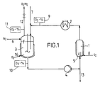
- a propulsion jet reactor (1), a heat exchanger (2), a stirred reactor (3) and a centrifugal pump (4) are connected to one another via pipes in a circuit system.
- a pulse exchange space (5) is indicated in the lower part of the propulsion jet reactor.
- the required volume of the aromatic C 7 to C 10 hydrocarbon is introduced at (7) in such a way that up to 90% of the usable circulatory volume is filled.
- the catalyst complex is also fed in at (7).
- the amount of phenol to be polymerized is then metered in via the same feed nozzle (7) in such a way that the feed time is up to 90% of the total reaction time required.
- a device for the supply of oxygen in the jet reactor (1) is designated.
- the concentration of the dissolved oxygen can be measured at (9) and (10).
- the measuring device (11) detects the oxygen content in the exhaust line (12). When a required intrinsic viscosity of the polymer solution is reached, it is fed to the further process stages via a pipe (13).
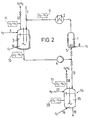
- the pipeline (13) opens into a further reactor unit (14).
- This includes a stirred reactor (15), a device (16) for the supply of oxygen and pipes (17) for the supply of nitrogen, (18) for the discharge of the exhaust gas and (19) for the discharge of the reaction product.
- a heating device (20) is connected to the exhaust line (18).
- Another measuring device (20) for determining the oxygen dissolved in the reaction solution is connected to the stirred reactor (15).
- the reaction solution is gassed with oxygen in the propulsion jet reactor.
- a start value for the entry rate of oxygen of 30 l / h is first set.
- the oxygen input is subsequently regulated in such a way that the oxygen content in the exhaust gas does not rise above 4% with a constant nitrogen input of 80 l / h.
- polyphenylene ether with an intrinsic viscosity of 0.63 dl / g, measured at 25 ° C. in chloroform, and a by-product fraction of diphenoquinone of 0.6%, based on the monomer used, is obtained.
- Example 1 was repeated with the difference that 10 minutes after the monomer had been fed in, the reaction solution was conveyed from the circulation system into a further stirred reactor (FIG. 2) and gas was passed on there at a constant rate of 10 l / h of oxygen.
- polyphenylene ether with an intrinsic viscosity of 0.66 dl / g, measured at 25 ° C. in chloroform, and a by-product fraction of diphenoquinone of 0.6%, based on the monomer used, was obtained.
Landscapes
- Chemical & Material Sciences (AREA)
- Organic Chemistry (AREA)
- Chemical Kinetics & Catalysis (AREA)
- Health & Medical Sciences (AREA)
- Medicinal Chemistry (AREA)
- Polymers & Plastics (AREA)
- Polyethers (AREA)
- Organic Low-Molecular-Weight Compounds And Preparation Thereof (AREA)
Description
- Die Erfindung bezieht sich auf ein Verfahren zur Herstellung von Polyphenylenethern nach dem Oberbegriff des Anspruchs 1 sowie auf eine Vorrichtung zur Durchführung des Verfahrens.
- Polyphenylenether und Verfahren zu ihrer Herstellung sind beispielsweise aus den US-Patentschriften 3 306 874 und 3 306 875 bekannt. Danach wird die Polymerisation durch oxidative Kupplung einwertiger Phenole in einem oder mehreren Rührreaktoren, die mit Kühlschlangen und Mantelkühlung sowie mit einem Gaseinleutungsrohr versehen sind, unter Vorlage des Katalysatorkomplexes aus Cu-Salzen und Aminen und der Phenole oder unter teilweisem oder vollständigem Zulauf des Katalysatorkomplexes und/oder der Phenole diskontinuierlich durchgeführt. Der Sauerstoff wird in konstanter Menge pro Zeiteinheit zudosiert.
- Aus der EP-A 287 670 ist ein Verfahren zur Herstellung von Polyphenylenethern bekannt, wobei die Umsetzung in einem Treibstrahlreaktor erfolgt.
- Diese fast vollständig abgasfreie ausschließlich diskontinuierliche Verfahrensform erfordert aus sicherheitstechnischen Gründen eine genaue Einhaltung der Druck- bzw. Partialdruckbedingungen und bei Beendigung der Reaktion enorme Inertgasüberdrücke von 100 bar.
- Weiterhin ist in WO 83/03833 ein Verfahren beschrieben, bei dem monomere Phenole zusammen mit Lösungsmittel einem sogenanntnen Begasungsrührreaktor, in dem ein Katalysatorkomplex vorgelegt ist, mit konstanter Sauerstofzuführ über einen bestimmten Zeitraum unter konstanter Geschwindigkeit mit dem Ziel zudosiert werden, das Molekulargewicht der Polyphenylenether gezielt umzustellen bzw. die Nebenproduktbildung zu 4,4-Diphenochinonen zu reduzieren.
- Die bekannten Verfahren, insbesondere die dort praktizierte Sauerstoffdosierung befriedigen jedoch nicht in jeder Hinsicht. Um die Emission so niedrig wie möglich zu halten, ist es erforderlich, den Inertgasanteil im Abgas niedrig zu halten. Dabei lassen sich explosive Gasgemische nur dann zuverlässig vermeiden, wenn der Gas-holdup in der Flüssigphase gering ist, was zwangsläufig zu einer geringem Raum-Zeit-Ausbeute führt. Wird dagegen die Raum-Zeit-Ausbeute durch einen entsprechenden hohen Sauerstoffdurchsatz erhöht, erhält man durch die zur Vermeidung einer explosiblen Gasatmosphäre notwendige Inertgasverdünnung hohe Emissionswerte und damit Verluste an flüchtigen Bestandteilen des Reaktionsgemisches. Ein konstanter Gaseintrag bzw. eine nicht an der Reaktion und Nebenproduktbildung orientierte kontrollierte Sauerstoffzufuhr birgt zudem den Nachteil, daß die für die Gasdispergierung aufzubringende Dissipationsenergie nicht anforderungsgemäß, sondern im Überschuß eingebracht werden muß.
- Darüber hinaus arbeiten die genannten Verfahren aufgrund mangelnder Ausnutzung, vorhandener Anlagenkapazitäten unwirtschaftlicht. Insbesondere die Kapazität des Wärmetauschers wird nur während der Olimerisierungsphase vollständig ausgenutzt.
- Es war Aufgabe der Erfindung, die Herstellung von Polyphenylenethern dahingehend zu verbessern, daß bei möglichst hohem Raum-Zeit-Ausbeuten, geringer Nebenproduktbildung, minimalen Emissionen an Gas und flüchtigen Bestandteilen die oxidative Kupplung von Phenolen mit Sauerstoff wirtschaftlich und sicher durchgeführt werden kann.
- Diese Aufgabe wird durch die Maßnahmen nach den Patentansprüchen gelöst.
- Unter hochmolekularen Polyphenylenethern im Simme der Erfindung werden die durch oxidative Kupplung von 2,6-Dialkyl- und/oder 2,3,6-Trialkylphenolen zu einer Kette alkylsubstituierter, in para-Stellung durch Sauerstoffatome etherartig gebundene Benzolringe verstanden. Die Polymeren weisen zahlenmittlere Molekulargewichte von 10 000 bis 30 000, bevorzugt 20 000 bis 30 000, bestimmt nach der in "Macromolecular Syntheses" 1 (1978), Seite 83 beschriebenen Methode, auf. Hochmolekulare Polyphenylenether sind aus US―PS 3 661 848, US―PS 3 219 625 oder US-PS 3 378 505 bekannt.
- Die zur Herstellung der hochmolekularen Polyphenylether verwendeten einwartigen Phenole, die in den beiden ortho-Stellungen, nicht aber in der para-Stellung Alkylsubstituenten aufweisen, sind übliche Phenole wie 2,6-Dimethylphenol, 2,6-Diethylphenol, 2-Methyl-6-ethylphenol, 2-Methyl-6-tertiär-butylphenol, 2-Methyl-6-propylphenol, 2,6-Dibutylphenol, 2,3,6-Trimethylphenol sowie Gemischt dieser Phenole.
- Bevorzugt wird das für die Polymerisation vorgesehene einwertige Phenol mit einem o-Kresol-und p-Kresol-Anteil von jeweils weniger als 0,1 Gew.% eingesetzt. Besonders bevorzugt wird ein einwertiges Phenol der oxidativen Kupplung unterzogen, das weniger als 0,05 Gew.% o-Kresol und weniger als 0,01 Gew.% p-Kresol enthält. Insbesondere bevorzugt ist ein Verfahren, bei dem Phenol, m-Kresol und mehrkernige Phenole zu weniger als 0,02 Gew.% in den Ausgangsstoffen enthalten sind.
- Bei dem für die oxidative Kupplung verwendeten Katalysatorkomplex handelt es sich um eine Kombination aus einem oder mehreren Aminen, wie Dibutylamin, Diethylamin, N,N'-Di-tert.-butyl- ethylendiamin, Picolin, Chinolin, Pyridinbasen, Triisopropylamin, Dimethylbutylamin, Dimethylisopropanolamin, Triethanolamin, Triisopropanolamin, Diisopropanolamin oder N-Butylimidazol mit einem Kupfersalz, wie Kupfer-I-Bromid, Kupfer-I-Chlorid, Kupfer-I-Jodid, Kupfer-II-Acetat, Kupfer-II-Propionat, Kupfer-II-Acetessigester oder Kupfer-II-Acetylacetonat.
- Kupfer-I/II-halogenide können dabei auch aus Kupferoxid durch Umsetzung mit Halogenwasserstoff erzeugt werden.
- Ein bevorzugter Bereich bei der Menge der eingesetzten Amine liegt üblicherweise bei 2,0 bis 25,0 Mol pro 100 Mol des Monomeren, die Konzentration der Amine kann aber in der Reaktionsmischung innerhalb weiter Grenzen variieren, zweckmäßig sind jedoch niedere Konzentrationen. Die Konzentration der Kupfersalz wird gering gehalten und variiert vorzugsweise von 0,2 bis 2,5 Mol pro 100 Mol des Monomeren.
- Die oxidative Kupplung kann jedoch auch in Gegenwart von Mn-Chelatkomplexen durchgeführt werden, wie dies beispielsweise in der DE-OS 27 52 294 beschrieben ist. Vorzugsweise werden Mn-II-hydroxyoxim-Chelatkomplex verwendet.
- Der Anteil des Lösungsmittels liegt üblicherweise im Bereich von 1:1 bis 20:1, d.h. maximal bis zu einem Überschub des 20-fachen an Lösungsmittel, bezogen auf das Monomere. Es soll als Lösungsmittel ein aromatischer C7- bis C10-Kohlenwasserstoff verwendet werden, der gegebenenfalls noch geringe Mengen eines Alkanols enthalten kann. Geeignete Kohlenwasserstoffe sind insbesondere Ethylbenzol, Xylol, Diethylbenzol oder deren Gemische, wobei vorzugsweise Ethylbenzol doer Toluol verwendet werden. Geeignete Alkanole sind bekannt, z.B. Ethanol und/oder Isopropanol. Die Lösungsmittel werden bevorzugt im Bereich von 1:1 bis 10:1 Gewichtsteile, bezogen auf das monomere Phenol, eingesetzt.
- Darüber hinaus kann gemäß der US―PS 3 544 515 die Reaktionsmischung einen Aktivator wie ein Diarylguanidin, ein Diarylformamidin oder Alkalimetall enthalten.
- Bei dem erfindungsgemäßen Polymerisationsverfahren erfolgt die Umsetzung der einwertigen Phenole in wenigstens zwei Reaktionszonen. Diese bestehen vorzugsweise zum einen aus einem Treibstrahlreaktor und zum anderen aus einem Rührreaktor. Zwischen den Reaktionszonen sind Wärmetauscher und ein Förderaggregat vorgesehen. Zur oxidativen Kupplung werden dem Treibstrahlreaktor etwa 60% bis 100% und dem Rührreaktor 0 bis etwa 40% der stöchiometrisch erforderlichen Sauerstoffmenge zugeführt. Vorzugsweise wird der Sauerstoff so zugeführt, daß mehr als 95% der Sauerstoffmenge umgesetzt werden. Unter der stöchiometrisch erforderlichen Menge Sauerstoff ist die Menge zu verstehen, die benötigt wird, um die Phenole zu Polyphenylenethern mit Grenzviskositäten von 0,4 bis 1,0 dl/g, gemessen bei 25°C in Chloroform, zu kuppeln. Die oxidative Kupplung wird dabei entweder unter Vorlage der gesamten Monomeren-, Lösungsmittel- und Katalysatormenge oder unter Vorlage der gesamten Katalysatormenge zusammen mit einem Teil des Lösungsmittels und gegebenenfalls des Phenols und unter Zulauf der restlichen Phenolmenge mit oder ohne Lösungsmittel durchgeführt. Bei dieser Fahrweise liegen zu Beginn des Zulaufs bis zu 90 Vol.% der flüssigen Anteile des gesamten Reaktionsgemisches in den Reaktionszonen Vor. Es hat sich gezeigt, daß dadurch der Anteil an Nebenprodukten, wie 3,3',5,5-Tetramethyl-4,4'- diphenochinon, bezogen auf das eingesetzte Phenol, unter 0,7% liegt. Die oxidative Kupplung wird kontinuierlich oder diskontinuierlich unter weitgehend isothermen und isobaren Bedingungen bei im allgemeinen 15 bis 50°C, vorzugsweise 25 bis 30 und bei 1 bis 10 bar, vorzugsweise 1 bis 4 bat absolut durchgeführt. Unter weitgehend isothermen Bedingungen soll verstanden werden, daß die Temperatur am Ausgang der Wärmetauscher lediglich in einem Bereich von ±3'C schwankt. Weitgehend isobare Bedingungen soll heißen, daß der Druck in der Gasphase der zweiten Reaktionszone etwa ±0,2 bar abweicht. Die für eine isotherme Fahrweise eingesetzten Wärmetauscher sind so ausgelegt, daß eine Entmischung der Gas-Flüssigdispersion verhindert wird.
- Das Förderaggregat hat die Aufgabe, eine für die Abführung der Reaktionswärme im Wärmetauscher notwendige Fördermenge bereitzustellen, und die für die Dispergierung der Gasphase in der ersten Reaktionszone erforderliche Dissipationsenergien einzutragen. Dabei ist konstruktiv zu gewährleisten, daß bis zu 20 Vol.% Gasanteile in der Flüssigphase mitgefördert werden können.
- Das stündliche Umwälzvolumen liegt üblicherweise im Bereich des 5- bis 50-fachen des Gesamtvolumens in den Reaktionszonen.
- Besondere Bedeutung beim erfindungsgemäßen Verfahren hinsichtlich Emission an Gasen und flüchtigen Bestandteilen, Sicherheit, und Raum-Zeit-Ausbeute, kommt der Dosierung des für die oxidative Kupplung notwendigen Sauerstoffs in den Reaktionszonen zu. Ein sicherer Betrieb ist dann gewährleistet, wenn die Konzentration des Sauerstoffs im Abgas der zweiten Reaktionszone unterhalb der unteren Explosionsgrenze liegt. Dazu wird die Konzentration des Sauerstoffs im Abgas der zweiten Reaktionszone mit handelsüblichen Meßsonden, z.B. Hersch-oder Clarkzellen, gemessen. Vor Erreichen der kritischen Sauerstoffkonzentration wird Stickstoff als Verdünnung in den Gasraum der zweiten Reaktionszone zugegeben. Alternativ dazu kann zur Vermeidung der kritischen Sauerstoffkonzentration die Zufuhr von Sauerstoff in die erste und/ oder zweite Reaktionszone reduziert werden.
- Durch die vorgenannten Maßnahmen für die Dosierung des Sauerstoffs wird eine sichere Fahrweise bei niedrigen Emissionswerten erreicht. Eine an der Reaktion und Nebenproduktbildung orientierte kontrollierte Sauerstoffzufuhr ist durch die Ermittlung des in der Flüssigphase gelösten Sauerstoffs in den Reaktionszonen möglich. Diese mikrokinetische Kenngröße erlaubt eine Quantifizierung des Reaktionsfortschritts und damit des tatsächlichen Sauerstoffbedarfs. Der Zeitraum der Oligomerisierungsphase und damit hohen Sauerstoffbedarfs läßt sich von der Polymerisierungsphase, d.h. der Phase mit niedrigerem Sauerstoffbedarf auf Grund dieser Meßgröße abgrenzen.
- Unter Oligomerisierungsphase wird der Zeitraum bis zum Erreichen eine Grenzviskosität von 20,1 dl/g, gemessen in Chloroform bei 25°C, verstanden.
- In Verbindung mit der Messung des Sauerstoffgehaltes im Abgas, läßt sich somit die Sauerstoffdosierung in der Weise regeln, daß während der Reaktion die Konzentration des gelösten Sauerstoffs nach der ersten Reaktionszone größer als 60% der Sättigungskonzentration beträgt und daß bei einer Konzentration gemessen nach oder in der zweiten Reaktionszone zwischen ca. 30%- ca. 80% des Sättigungwertes der Sauerstoffeintrag in die erste und/oder die zweite Reaktionszone reduziert wird.
- Die Sättigungskonzentration ist dabei die Gleichgewichtskonzentration beim Arbeitsdruck und bei der Arbeitstemperatur in einer Polymerlösung mit einer Grenzviskosität von 0,4 dl/g, gemessen bei 25°C in Chloroform.
- Vorteile dieser Maßnahmen sind ein sichertes Betreiben der Anlage bei maximaler Raum-Zeit-Ausbeute und minimalen Emissionen an Gasen und flüchtigen Bestandteilen.
- Nach der Erfindung wird schließlich auch ein überraschend niedriger Gehalt an Nebenprodukten wie 4,4'-Diphenochinonen von kleiner als 0,7% bezogen auf das eingesetzte Phenol, erhalten.
- In einer besonders bevorzugten Ausführungsform des erfindungsgemäßen Verfahrens wird die gesamte Reaktionslösung nach Erreichen eines Umsatzes von 80% des insgesamt stöchiometrisch benötigten Sauerstoffs in eine dritte Reaktionszone gefördert und dort bis zum Aufbau einer Grenzviskosität zwischen 0,4 dl/g und 1 dl/g, gemessen bei 25°C in Chloroform, weiterpolymerisiert. In der ersten und zweiten Reaktionszone werden die Monomere zu Oligomeren umgesetzt. Nach deren Überführung in die dritte Reaktionszone stehen somit die erste und zweite Reaktionszone für die Oligomerisierung eines neuen Ansatzes zur Verfügung. Dies hat zur Folge, daß die installierten Apparateteile, die prinzipiell für hohen Sauerstoffbedarf, große Wärmeentwicklung, hohe Umwälzleistungen sowie die Erzeugung einer ausreichend großen Stoffaustauschfläche ausgelegt sind, zu jedem Zeitpunkt optimal nutzbar sind. In der dritten Reaktionszone, in der die Oligomeren zu Polymeren reagieren, sind Wärmetauscher, und Förderaggregate nicht unbedingt erforderlich. Es hat sich gezeigt, daß auf diese Weise eine erhebliche Steigerung der Raum-Zeit-Ausbeute, sowie einem höheren Apparatewirkungsgrad erreichbar sind. Zudem lassen sich die teilweise empfindlichen apparativen Einrichtungen derart nutzen, daß Verkrustungen bzw. Verklebungen der eingesetzten Produkte auch bei hohen Konzentrationen an Phenolen praktisch nicht auftreten.
- Im wesentlichen gelangt der für den Aufbau der Polymeren noch notwendige Sauerstoffe in physikalisch gelöster Form aus der ersten und zweiten Reaktionszone zusammen mit der Reaktionslösung in die dritte Reaktionszone. Bei Bedarf kann indes in die dritte Reaktionszone zusätzlich gasförmiger Sauerstoff eindosiert werden. Wegen des nur noch geringen Sauerstoffbedarfs in der dritten Reaktionszone ist eine isotherme Fahrweise auch ohne Kühlkapazitäten, gewährleistet. Emissionen an Gasen und flüchtigen Bestandteilen werden weitgehend vermieden.
- Ein Vorrichtung zur Durchführung des Verfahrens nach der Erfindung besteht aus wenigstens zwei Reaktoreinheiten, von denen eine Reaktoreinheit als Treibstrahlreaktor und eine bzw. die weiteren Reaktoreinheit(en) als Rührreaktor(en) ausgebildet sind. In den vorzugsweise kühlbaren Treibstrahlreaktor wird die Flüssigphase über eine Strahldüse im unteren Reaktorteil so zugeführt, daß sie in scharfem Strahl den im Kreuzstrom dazu über ein Gaseinleitungsrohr zudosierten Sauerstoff dispergiert. Diese Primärdispersion wird durch einen im Treibstrahlreaktor oberhalb der Strahldüse angeordneten Impulsaustauschraum feinstdispergiert. Die Ausbildung einer großen Stoffaustauschfläche im Treibstrahlreaktor bewirkt eine hohe Stoffübergangsrate. Wagen der hohen Stoffaustauschleistung verläuft die Reaktion kinetisch kontrolliert. Der Reaktorwirkungsgrad liegt somit nahe eins.
- Der Hauptteil der im Treibstrahlreaktor entstehenden Reaktionswärme wird im nachgeschalteten Wärmetauscher abgeführt. Dabei wird soviel Kühlleistung bereitsgestellt, daß am Wärmetauscherausgang produktseitig Isothermie eingestellt ist. Der Wärmetauscher ist so auszulegen, daß die den Treibstrahlreaktor verlassende Gas-Flüssigdispersion keine Separierung der Phasen erfährt und die Wärmetauscherwände frei von Belag bleiben. Diese bewirkt das Aufrechterhalten der feinen Gasdispersion und das Erzielen hoher Wärmeübergangszahlen. Zudem wird die den Treibstrahlreaktor verlassende Gas-Flüssigphase dispers gehalten.
- Im nachfolgenden Rührreaktor ist somit ein Dispergierorgan nicht erforderlich, sondern lediglich ein Rührorgan, welches durch Ausbildung einer Schichtenströmung ein Aufsteigen der dispersen Gasphase verhindert. Dem im allgemeinen kühlbaren Rührreaktor wird die disperse Reaktionslösung über ein Tauchrohr zugeführt. Im freien Gasraum des Rührreaktors erfolgt die unter Umständen notwendige Inertisierung mit Stickstoff in der Weise, daß ein Konzentrationsgradient innerhalb des Gasraums vermieden wird, wodurch eine sichere Betriebsweise gewährleistet ist.
- Für die Aufrechterhalten einer Kreislaufförderung der Reaktionslösung ist nach dem Rührreaktor ein Förderaggregat vorgesehen. Als Förderaggregat kommt eine solche Pumpe in Betracht, bei der Gasantsile von bis zu 20 Vol.% die Funktion der Pumpe nicht beeinträchtigt, eine Separation der Gas-Flüssigdispersion aufgrund des Beschleunigungsfeldes in der Pumpe verhindert wird und keine Kavitation auftritt. Als geeignet erwiesen haben sich Kreiskolbenpumpen und Kreiselpumpen, insbesondere Kreiselpumpen mit Leitblechen am Saugstutzen oder auf der Welle angebrachte Inducer. Die Durchsatzleistung der Pumpe ist so zu wählen, daß einerseits die für die Dispergierung der Gasphase im Treibstrahlreaktor notwendige Treibstrahlenergie aufgebracht wird und andererseits im Wärmetauscher eine Strömungsgeschwindigkeit realisierbar ist, welche die Funktion des Wärmetauschers nicht beeinträchtig. Das stündlich umgewälzte Volumen beträgt zweckmäßig das 5- bis 50-fache, vorzugsweise das 6- bis 20-fache des Inhalts des Kreislaufsystems.
- Nach einem weiteren Merkmal der Erfindung können sich nach dem Förderaggregat ein oder mehrere, parallel oder in Reihe geschaltete, durch Rohrleitungen mit dem Kreislaufsystem verbundene Rührreaktoren Anschließen. Es ist danach möglich, die oxidative Kupplungsreaktion sowohl kontin-uierlich als auch diskontinuierlich durchzuführen. Bei kontinuierlicher Fahrweise sind die Rührreaktoren in Reihe geschaltet, wobei wenigstens der erste Rührkessel mit einer Einrichtung für die Zufuhr von Sauerstoff ausgerüstet ist. Bei diskontinuierlicher Fahrweise und Verwendung mehrerer Rührreaktoren sind diese parallel geschaltet.
die Erfindung wird nachfolgend unter Hinweis auf die Zeichnungen anhand zweier Ausführungsbeispiele näher erläutert. - Nach figur 1 sind in einem Kreislaufsystem ein Treibstrahlreaktor (1), ein Wärmetauscher (2), ein Rührreaktor (3) und eine Kreiselpumpe (4) über Rohrleitungen miteinander verbunden. Im unteren Teil des Treibstrahlreaktors ist ein Impulsaustauschraum (5) angedeutet. Nach dem Inertisieren des Kreislaufsystems mit Stickstoff über die Zuleitung (6) wird das erforderliche Volumen des aromatischen C7- bis C10-Kohlenwasserstoffs bei (7) so eingebracht, daß bis zu 90% des nutzbaren Kreislaufvolumens gefüllt ist. Der Katalysatorkomplex wird nach Inbetriebnahme des Rührwerks des Rührreaktors (3) und der Kreiselpumpe (4) ebenfalls bei (7) zugeführt. Anschließend erfolgt die Dosierung der zu polymerisierenden Phenolmenge über den selben Zulaufstutzen (7) derart, daß die Zulaufzeit bis zu 90% der insgesamt benötigten Reaktionszeit beträgt.
- Mit (8) ist eine Einrichtung für die Zufuhr von Sauerstoff in den Treibstrahlreaktor (1) bezeichnet. Die Konzentration des gelösten Sauerstoffs ist bei (9) und (10) meßbar. Die Meßeinrichtung (11) erfaßt den Sauerstoffgehalt in der Abgasleitung (12). Bei Erreichen einer geforderten Grenzviskosität der Polymerlösung wird diese über eine Rohrleitung (13) den weiteren Verfahrensstuffen zugeführt.
- Gemäß Figur 2 mündet die Rohrleitung (13) in einer weiteren Reaktoreinheit (14). Diese umgaßt einen Rührreaktor (15), eine Einrichtung (16) für die Zufuhr von Sauerstoff sowie Rohrleitungen (17) für die Zufuhr von Stickstoff, (18) für die Ableitung des Abgases und (19) für den Austrag des Reaktionsproduktes. An die Abgasleitung (18) ist eine Heßeinrichtung (20) angeschlossen. Eine weitere Meßeinrichtung (20) zur Bestimmung des in der Reaktionslösung gelösten Sauerstoffs ist mit dem Rührreaktor (15) verbunden.
- In dem in Figur 1 dargestellten Kreislaufsystem wird folgende Mischung vorgelegt:
- 45,76 Mol Toluol
- 0,807 Mol Kupfer-I-bromid
- 1,596 Mol Di-n-butylamin.
- In diese, mit einem Durchsatz von 120 I/h umgewälzte, über den Rührreaktor mit 80 I/h Stickstoff inertisierte und auf 25°C temperierte Lösung, wird eine Monomerlösung, bestehend aus:
- 8,00 Mol 2,6-Dimethylphenol
- 9,90 Mol Toluol
- dem Rührreaktor innerhalb 30 min eindosiert. Die Reaktionslösung wird mit dem Beginn des Monomerenzulaufs mit Sauerstoff im Treibstrahlreaktor begast. Dazu wird zunächst ein Startwert für die Eintragsrate an Sauerstoff von 30 I/h eingestellt. Durch Messung des Sauerstoffgehaltes in der Abgasleitung sowie durch Messung des in der Flüssigphase gelösten Sauerstoffs wird der Sauerstoffeintrag in der Folge in der Weise geregelt, daß bei konstantem Stickstoffeintrag von 80 I/h der Sauerstoffgehalt im Abgas nicht über 4% ansteigt. Nach 60 min Reaktionszeit wird Polyphenylenether mit einer Grenzviskosität von 0,63 dl/g, gemessen bei 25°C in Chloroform, und einem Nebenproduktanteil an Diphenochinon von 0,6%, bezogen auf das eingesetzte Monomere erhalten.
- Beispiel 1 wurde mit dem Unterschied wiederholt, daß 10 min nach dem Monomerenzulauf die Reaktionslösung aus dem Kreislaufsystem in einen weiteren Rührreaktor (Figur 2) gefördert und dort mit einer konstanten Sauerstoffeintragsrate von 10 I-h weiterbegast wurde.
- Nach 120 min Gesamtreaktionszeit wurde Polyphenylenether mit einer Grenzviskosität von 0,66 dl/g, gemessen bei 25°C in Chloroform, und einem Nebenproduktanteil an Diphenochinon von 0,6%, bezogen auf das eingesetzte Monomere, erhalten.
Claims (11)
Applications Claiming Priority (2)
| Application Number | Priority Date | Filing Date | Title |
|---|---|---|---|
| DE3442117 | 1984-11-17 | ||
| DE3442117 | 1984-11-17 |
Publications (3)
| Publication Number | Publication Date |
|---|---|
| EP0182206A2 EP0182206A2 (de) | 1986-05-28 |
| EP0182206A3 EP0182206A3 (en) | 1987-10-28 |
| EP0182206B1 true EP0182206B1 (de) | 1990-06-27 |
Family
ID=6250579
Family Applications (1)
| Application Number | Title | Priority Date | Filing Date |
|---|---|---|---|
| EP85114158A Expired - Lifetime EP0182206B1 (de) | 1984-11-17 | 1985-11-07 | Verfahren und Vorrichtung zur Herstellung von Polyphenylenethern |
Country Status (4)
| Country | Link |
|---|---|
| US (1) | US4696996A (de) |
| EP (1) | EP0182206B1 (de) |
| CA (1) | CA1263992A (de) |
| DE (1) | DE3578428D1 (de) |
Families Citing this family (12)
| Publication number | Priority date | Publication date | Assignee | Title |
|---|---|---|---|---|
| DE3512759A1 (de) * | 1985-04-10 | 1986-10-23 | Basf Ag, 6700 Ludwigshafen | Verfahren zur kontinuierlichen herstellung von polyphenylenethern |
| JPH0794555B2 (ja) * | 1988-10-20 | 1995-10-11 | 三井東圧化学株式会社 | ポリイミドシートの製造方法 |
| DE3919229A1 (de) * | 1989-06-13 | 1990-12-20 | Basf Ag | Verfahren zur herstellung von polyphenylenether durch oxidative kupplungsreaktion in loesung |
| US6417274B1 (en) | 1999-02-05 | 2002-07-09 | General Electric Co. | Process for the manufacture of functionalized polyphenylene ether resins |
| US6211327B1 (en) | 1999-02-05 | 2001-04-03 | General Electric Company | Process for the manufacture of low molecular weight polyphenylene ether resins |
| US6407202B1 (en) | 2000-07-14 | 2002-06-18 | General Electric Company | Poly(arylene ether) and process for making the same |
| ITVA20050074A1 (it) * | 2005-12-23 | 2007-06-24 | Lamberti Spa | Riduttore di filtrato per fanghi di perforazione |
| WO2016200791A1 (en) * | 2015-06-09 | 2016-12-15 | Sabic Global Technologies B.V. | Method for poly(phenylene ether) manufacture and associated poly(phenylene ether) |
| CN108371932B (zh) * | 2017-12-29 | 2020-07-03 | 上海载正化工科技发展有限公司 | 一种制备小分子量聚苯醚的反应系统和方法 |
| CN108371931B (zh) * | 2017-12-29 | 2020-07-03 | 上海载正化工科技发展有限公司 | 一种合成小分子量聚苯醚的生产设备 |
| CN113272357A (zh) | 2018-10-18 | 2021-08-17 | 高新特殊工程塑料全球技术有限公司 | 制备聚(亚苯基醚)的方法、由其制备的聚(亚苯基醚)及包含聚(亚苯基醚)的制品 |
| US11472920B2 (en) * | 2019-01-22 | 2022-10-18 | Shpp Global Technologies B.V. | Method for preparing a poly(phenylene ether) and poly(phenylene ether) prepared thereby |
Family Cites Families (12)
| Publication number | Priority date | Publication date | Assignee | Title |
|---|---|---|---|---|
| NL295748A (de) * | 1962-07-24 | |||
| BE635350A (de) * | 1962-07-24 | |||
| AU6624865A (en) * | 1965-11-08 | 1967-05-11 | Nv. Onderzoekjngsinstituut Research | Improvements in and relating tothe oxidation of phenols |
| US3432469A (en) * | 1967-02-02 | 1969-03-11 | Gen Electric | Process for producing high molecular weight polymers from impure 2,6-xylenol |
| DE3206661A1 (de) * | 1982-02-25 | 1983-09-01 | Basf Ag, 6700 Ludwigshafen | Verfahren zur vermeidung einer explosiblen gasphase bei gas/fluessig-reaktionen |
| EP0107653A4 (de) * | 1982-05-04 | 1984-09-13 | Gen Electric | Polymerisierungsverfahren von phenolen bei niedrigem sauerstofffluss. |
| EP0103154A1 (de) * | 1982-08-16 | 1984-03-21 | General Electric Company | Kontinuierliches Verfahren zur Herstellung eines Polyphenylenetherharzes unter Verwendung einer hohen Konzentration an Bromid-Ionen |
| US4578449A (en) * | 1983-03-25 | 1986-03-25 | General Electric Company | Two-stage process for preparation of polyphenylene oxides |
| US4477649A (en) * | 1983-03-25 | 1984-10-16 | General Electric Company | Two-stage continuous process for preparation of polyphenylene oxides |
| US4503214A (en) * | 1983-12-05 | 1985-03-05 | General Electric Company | Continuous process for preparing polyphenylene oxides |
| IT1167678B (it) * | 1983-12-05 | 1987-05-13 | Enichimica Spa | Procedimento perfezionato per la produzione di polifenilenossido |
| US4556699A (en) * | 1984-12-03 | 1985-12-03 | Enichimica S.P.A. | Process for the production of polyphenylene oxide |
-
1985
- 1985-11-07 DE DE8585114158T patent/DE3578428D1/de not_active Expired - Lifetime
- 1985-11-07 EP EP85114158A patent/EP0182206B1/de not_active Expired - Lifetime
- 1985-11-14 US US06/797,884 patent/US4696996A/en not_active Expired - Lifetime
- 1985-11-15 CA CA000495489A patent/CA1263992A/en not_active Expired
Also Published As
| Publication number | Publication date |
|---|---|
| CA1263992A (en) | 1989-12-19 |
| US4696996A (en) | 1987-09-29 |
| EP0182206A3 (en) | 1987-10-28 |
| DE3578428D1 (de) | 1990-08-02 |
| EP0182206A2 (de) | 1986-05-28 |
Similar Documents
| Publication | Publication Date | Title |
|---|---|---|
| EP0182206A2 (de) | Verfahren und Vorrichtung zur Herstellung von Polyphenylenethern | |
| DE3410386C2 (de) | ||
| DE68925101T2 (de) | Extruder-Polymerisation von Polyurethanen | |
| DE60121929T2 (de) | Verfahren und apparatur zur herstellung von polyanilin | |
| DE1145360B (de) | Verfahren zur Oxydation von Phenolen mit Sauerstoff | |
| DE4327805A1 (de) | Verfahren zur Herstellung von polymerem Material | |
| EP0020946B1 (de) | Verfahren zur kontinuierlichen Herstellung von Polycaprolactam sowie eine Vorrichtung zur Durchführung des Verfahrens | |
| DE3419331C2 (de) | Verfahren zur Herstellung von Polyphenylenätherharz | |
| EP1224229A1 (de) | Verfahren zur herstellung von hochreaktiven polyisobutenen | |
| DE60315999T2 (de) | Polyolefin-suspensionsschlaufenreaktor | |
| CH637309A5 (de) | Kontinuierliches verfahren zur durchfuehrung von vornehmlich stofftransportbedingten reaktionen. | |
| DE2822858C2 (de) | Verfahren zur Herstellung von mit Chinon gekuppelten Polyphenylenoxiden | |
| DE1520260C2 (de) | Verfahren zur Herstellung von Homo- oder Mischpolymerisaten des Äthylens | |
| DE3044803C2 (de) | ||
| DE3213735C2 (de) | Verfahren und Vorrichtung zum kontinuierlichen Herstellen von hochschlagfestem Polystyrol | |
| EP0197469B1 (de) | Verfahren zur kontinuierlichen Herstellung von Polyphenylenethern | |
| DE3410385C2 (de) | Oxidatives Kupplungsverfahren zur Herstellung eines Polyphenylenoxids | |
| DE19911024A1 (de) | Verfahren zum Anfahren von Schlaufenreaktorsystemen, in denen zumindest eine exotherme Reaktion durchgeführt werden soll | |
| EP0402721B1 (de) | Verfahren zur Herstellung von Polyphenylenether durch oxidative Kupplungsreaktion in Lösung | |
| DE3515516A1 (de) | Verfahren zur kontinuierlichen herstellung von polyphenylenethern | |
| DE2401295C2 (de) | Verfahren zum Durchführen von exothermen Copolymerisationsreaktionen von Äthylen und Propylen und gegebenenfalls 1,4-Hexadien oder 5-Äthylidennorbornen | |
| DE69507082T2 (de) | Oxydation von sekundären Alkoholen | |
| DE2822859A1 (de) | Verfahren zur herstellung von acylgekoppelten polymeren von chinongekoppelten polyphenylenoxiden | |
| DE1244408B (de) | Verfahren zur Herstellung von Polyoxymethylenen durch kontinuierliches Polymerisieren von Trioxan in Masse | |
| DE4106320C2 (de) | Polymerisationsvorrichtung |
Legal Events
| Date | Code | Title | Description |
|---|---|---|---|
| PUAI | Public reference made under article 153(3) epc to a published international application that has entered the european phase |
Free format text: ORIGINAL CODE: 0009012 |
|
| AK | Designated contracting states |
Kind code of ref document: A2 Designated state(s): BE DE FR GB NL |
|
| PUAL | Search report despatched |
Free format text: ORIGINAL CODE: 0009013 |
|
| AK | Designated contracting states |
Kind code of ref document: A3 Designated state(s): BE DE FR GB NL |
|
| 17P | Request for examination filed |
Effective date: 19870912 |
|
| 17Q | First examination report despatched |
Effective date: 19890329 |
|
| GRAA | (expected) grant |
Free format text: ORIGINAL CODE: 0009210 |
|
| AK | Designated contracting states |
Kind code of ref document: B1 Designated state(s): BE DE FR GB NL |
|
| REF | Corresponds to: |
Ref document number: 3578428 Country of ref document: DE Date of ref document: 19900802 |
|
| GBT | Gb: translation of ep patent filed (gb section 77(6)(a)/1977) | ||
| ET | Fr: translation filed | ||
| PLBE | No opposition filed within time limit |
Free format text: ORIGINAL CODE: 0009261 |
|
| STAA | Information on the status of an ep patent application or granted ep patent |
Free format text: STATUS: NO OPPOSITION FILED WITHIN TIME LIMIT |
|
| 26N | No opposition filed | ||
| K2C3 | Correction of patent specification (complete document) published |
Effective date: 19900627 |
|
| ET1 | Fr: translation filed ** revision of the translation of the patent or the claims | ||
| REG | Reference to a national code |
Ref country code: GB Ref legal event code: IF02 |
|
| PGFP | Annual fee paid to national office [announced via postgrant information from national office to epo] |
Ref country code: FR Payment date: 20021017 Year of fee payment: 18 |
|
| PGFP | Annual fee paid to national office [announced via postgrant information from national office to epo] |
Ref country code: NL Payment date: 20021021 Year of fee payment: 18 |
|
| PGFP | Annual fee paid to national office [announced via postgrant information from national office to epo] |
Ref country code: GB Payment date: 20021101 Year of fee payment: 18 |
|
| PGFP | Annual fee paid to national office [announced via postgrant information from national office to epo] |
Ref country code: BE Payment date: 20021128 Year of fee payment: 18 |
|
| PGFP | Annual fee paid to national office [announced via postgrant information from national office to epo] |
Ref country code: DE Payment date: 20021213 Year of fee payment: 18 |
|
| PG25 | Lapsed in a contracting state [announced via postgrant information from national office to epo] |
Ref country code: GB Free format text: LAPSE BECAUSE OF NON-PAYMENT OF DUE FEES Effective date: 20031107 |
|
| PG25 | Lapsed in a contracting state [announced via postgrant information from national office to epo] |
Ref country code: BE Free format text: LAPSE BECAUSE OF NON-PAYMENT OF DUE FEES Effective date: 20031130 |
|
| PG25 | Lapsed in a contracting state [announced via postgrant information from national office to epo] |
Ref country code: DE Free format text: LAPSE BECAUSE OF THE APPLICANT RENOUNCES Effective date: 20031217 |
|
| BERE | Be: lapsed |
Owner name: *BASF A.G. Effective date: 20031130 |
|
| PG25 | Lapsed in a contracting state [announced via postgrant information from national office to epo] |
Ref country code: NL Free format text: LAPSE BECAUSE OF NON-PAYMENT OF DUE FEES Effective date: 20040601 |
|
| GBPC | Gb: european patent ceased through non-payment of renewal fee |
Effective date: 20031107 |
|
| PG25 | Lapsed in a contracting state [announced via postgrant information from national office to epo] |
Ref country code: FR Free format text: LAPSE BECAUSE OF NON-PAYMENT OF DUE FEES Effective date: 20040730 |
|
| NLV4 | Nl: lapsed or anulled due to non-payment of the annual fee |
Effective date: 20040601 |
|
| REG | Reference to a national code |
Ref country code: FR Ref legal event code: ST |