EP0180752B1 - Kochplatten-Stapelbeilage - Google Patents
Kochplatten-Stapelbeilage Download PDFInfo
- Publication number
- EP0180752B1 EP0180752B1 EP85112064A EP85112064A EP0180752B1 EP 0180752 B1 EP0180752 B1 EP 0180752B1 EP 85112064 A EP85112064 A EP 85112064A EP 85112064 A EP85112064 A EP 85112064A EP 0180752 B1 EP0180752 B1 EP 0180752B1
- Authority
- EP
- European Patent Office
- Prior art keywords
- hotplate
- support
- hotplates
- support members
- support unit
- Prior art date
- Legal status (The legal status is an assumption and is not a legal conclusion. Google has not performed a legal analysis and makes no representation as to the accuracy of the status listed.)
- Expired
Links
- 239000010410 layer Substances 0.000 claims abstract description 27
- 239000011241 protective layer Substances 0.000 claims abstract description 8
- 238000010438 heat treatment Methods 0.000 claims description 11
- 238000010411 cooking Methods 0.000 claims description 10
- 239000007787 solid Substances 0.000 claims description 4
- 239000004033 plastic Substances 0.000 claims description 2
- 238000006073 displacement reaction Methods 0.000 claims 1
- 239000011888 foil Substances 0.000 claims 1
- 230000007423 decrease Effects 0.000 description 3
- 229910001018 Cast iron Inorganic materials 0.000 description 2
- 229910001208 Crucible steel Inorganic materials 0.000 description 1
- 238000005452 bending Methods 0.000 description 1
- 239000000919 ceramic Substances 0.000 description 1
- 238000010276 construction Methods 0.000 description 1
- 238000003780 insertion Methods 0.000 description 1
- 230000037431 insertion Effects 0.000 description 1
- 239000002651 laminated plastic film Substances 0.000 description 1
- 239000002184 metal Substances 0.000 description 1
- 229910052751 metal Inorganic materials 0.000 description 1
- 238000004806 packaging method and process Methods 0.000 description 1
- 230000002093 peripheral effect Effects 0.000 description 1
- 239000002985 plastic film Substances 0.000 description 1
- 229920006255 plastic film Polymers 0.000 description 1
- 238000006748 scratching Methods 0.000 description 1
- 230000002393 scratching effect Effects 0.000 description 1
Images

Classifications
-
- B—PERFORMING OPERATIONS; TRANSPORTING
- B65—CONVEYING; PACKING; STORING; HANDLING THIN OR FILAMENTARY MATERIAL
- B65D—CONTAINERS FOR STORAGE OR TRANSPORT OF ARTICLES OR MATERIALS, e.g. BAGS, BARRELS, BOTTLES, BOXES, CANS, CARTONS, CRATES, DRUMS, JARS, TANKS, HOPPERS, FORWARDING CONTAINERS; ACCESSORIES, CLOSURES, OR FITTINGS THEREFOR; PACKAGING ELEMENTS; PACKAGES
- B65D85/00—Containers, packaging elements or packages, specially adapted for particular articles or materials
- B65D85/62—Containers, packaging elements or packages, specially adapted for particular articles or materials for stacks of articles; for special arrangements of groups of articles
-
- Y—GENERAL TAGGING OF NEW TECHNOLOGICAL DEVELOPMENTS; GENERAL TAGGING OF CROSS-SECTIONAL TECHNOLOGIES SPANNING OVER SEVERAL SECTIONS OF THE IPC; TECHNICAL SUBJECTS COVERED BY FORMER USPC CROSS-REFERENCE ART COLLECTIONS [XRACs] AND DIGESTS
- Y10—TECHNICAL SUBJECTS COVERED BY FORMER USPC
- Y10S—TECHNICAL SUBJECTS COVERED BY FORMER USPC CROSS-REFERENCE ART COLLECTIONS [XRACs] AND DIGESTS
- Y10S206/00—Special receptacle or package
- Y10S206/821—Stacking member
Definitions
- the invention relates to a hotplate stacking insert, each with a support unit for the spacing arrangement between two hotplates lying one above the other, in particular with their undersides, and with support surfaces provided on the upper and lower ends of support members of the support unit for the support system distributed on the hotplate circumference two associated hotplates.
- Electric hot plates for cooker hobs or the like which generally have a cast steel base body to be heated electrically, often have a very high weight on the one hand and on the other hand they are sensitive to damage, in particular by scratching the cooking heating surface formed by the base plate body. Therefore, the hot plates, if they are stacked for storage, transport or the like. To be stacked together, be supported particularly carefully and stably, in particular to prevent the hot plates from slipping in the stack.
- stacking safety depends on the skill of the person inserting the wooden blocks and that inserting the wooden blocks takes a relatively long time.
- special care must be taken when inserting the wooden blocks so that they do not come to lie in areas in which they could collide with those parts of the hotplates which are provided on the undersides of the hotplates.
- the invention has for its object to provide a stacking insert for hot plates, which ensures safe and precisely aligned stacking of the hot plates with simple handling.
- a hotplate stacking insert of the type mentioned according to the invention in that connecting links are provided for mutually aligned, direct connection of supporting links.
- connecting links are provided for mutually aligned, direct connection of supporting links.
- At least one connecting link connects all the support members of a support unit to one another, so that the hotplates can be arranged in vertical stacking columns and the support units of adjacent stacking columns are not directly connected to one another.
- the connecting member or the connecting members are formed in one piece with the associated supporting members, so that the respective stacking aid having two or more supporting members is simple, for. B. made of plastic.
- the support unit in particular on the respective support member, has at least one circumferential centering surface for the hot plate, the centering surface preferably being arranged following the radially outer boundary of the associated contact surface and above it, so that there is also side protection of the associated peripheral surface of the hotplate.
- the bearing surface is expediently adapted for contact with the lower end face of an annular flange, which is formed by the cast iron plate base body and protrudes in a ring, freely adjacent to the largest diameter of the hotplate, over its underside.
- the centering surface preferably formed by an arch web adjoining the outer circumference of the support unit, converges towards the support surface with the central axis of the hotplate, in particular enclosing an obtuse angle with the support surface and thereby forms a funnel-like insertion surface.
- two support members are arranged adjacent to one another on the circumference of the hotplate and these two support members form a gap between them, in particular a U-shaped cutout for engaging a hotplate connection body, which is usually in the form of a ceramic body or Like.
- a hotplate connection body which is usually in the form of a ceramic body or Like.
- this connector body comes to rest in the gap also results in a precisely defined arrangement of each hotplate in the stack with respect to the rotational position about the hotplate center axis, and in this arrangement the hotplate is fixed by the centering engagement of its connector body in the cutout of the stacking unit .
- Both hotplates can be easily inserted into the stacking unit in any order in the direction of their central axes.
- the contact surface between adjacent support members can extend in the form of an arc of a ring over the width of the gap, the two support members being connected to one another in this area by a connecting member delimiting the gap on the associated side.
- the support unit is free of support members on two sides opposite one another with respect to the hotplate center axis and is preferably delimited radially inwards with respect to the diameter of the respective support surface, so that the support unit is made even more compact.
- two diametrically opposed pairs of support members are provided, each pair of which has an arc angle of less than 180 °, in particular approximately 80 °, so that there is a very space-saving and reliable support design in the support unit.
- Opposing supporting links can be connected to one another in a sufficiently stable manner only via lateral tendon-like, essentially rectilinear and / or approximately right-angled connecting links to the hotplate central axis, preferably two parallel connecting links having approximately the same distances from the hotplate central axis, which are smaller compared to the radius of the support surface are and secure the support members against each other substantially stable.
- the compact design of the support unit or the stacking insert described by the features also benefits its return transport for reuse after the hot plates have been removed and the storage of the stacking device in the event of non-use.
- the support unit is designed to be stackable with a plurality of further, in particular identical support units of the stacking insert, the lateral connecting links preferably occupying only part of the height of the support links, in particular approximately in the middle of the height between the support surfaces and their inner surfaces are at least slightly offset to the outside in relation to the associated side surfaces, at least in the end connection area to the associated support members.
- two support units can be stacked one inside the other at a height that is significantly smaller than the added heights of the two support units, namely only about twice the height of the tendon-like connecting elements that lie directly on top of one another in the case of stacked support units, while the support members of each upper support unit on one side on the inner circumference and on the other side on the outer circumference of the underlying support unit.
- the uniform contact of the hot plates on the support surfaces can be significantly improved by the fact that adjacent support members are connected to one another in a flexible, expedient but elastically limited manner in a plurality of directions, in particular transverse to the support surfaces, preferably connecting members in the manner of bending rods slightly are deformable so that the frame-shaped support unit can be elastically entangled in itself, the tendon-like connecting elements twisting in the manner of torsion bars.
- all support members are slightly movable against each other, so that the respective support unit is automatically brought into the best support position under the weight of the hot plates.
- a particularly advantageous development of the subject matter of the invention is that the essentially parallel hotplate central axes of the two support surfaces, which are adapted to the hotplate undersides of two hotplates, on both sides of the respective support unit are offset from one another by at least the diameter of protruding fastening bolts on the undersides of the hotplates are, so that the two, in a support unit with their undersides engaging hot plates can be arranged with respect to their undersides with an axial distance from each other, which is only slightly larger than the length of the projecting over the underside part of the fastening or assembly bolt.
- the support members can be made compact part-shell-shaped despite the offset, they are slanted in axial section according to the offset, so that they form almost parts of a cylinder jacket which is cut obliquely to its central axis on two mutually parallel end faces.
- each of the hotplates which are not supported on one another by supporting units but with their cooking heating surfaces, gently abut against one another
- at least one plate-shaped intermediate layer is provided for the arrangement between each of these cooking heating surfaces supported against one another.
- this intermediate layer acts centering or fixing on at least one hotplate
- the intermediate layer expediently has on one side a centering recess for each hotplate to be placed and on the other side a smooth protective layer, in particular a laminated plastic film, so that the cooking heating surfaces are scratched is completely excluded by rubbing against each other.
- this intermediate layer which can have a plurality or a plurality of centering depressions next to one another in a grid, with the protective layer facing down onto the cooking heating surfaces of a number of hot plates arranged in the corresponding grid and then into the top open centering recesses a corresponding or equal number of hotplates in such a way that the hotplate base body forming the hotplate engages with its centered outer periphery adjoining the hotplate in the corresponding recess.
- the intermediate layer has a corrugated cardboard layer which is penetrated by the particularly circular centering recess and is provided on one side with a solid cardboard or the like forming the protective layer and the closed bottom of the centering recess, so that at simple structure and low thickness of the intermediate layer ensures high stability.
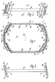
- a stacking insert 1 according to the invention for electric hot plates 2 has a multiplicity of identical, one-piece support units 3, which are not directly connected to one another and can be arranged at a short distance from one another in a rectangular row and column grid, as well as several one above the other, each between one Double layer of hotplates 2 to be arranged on flat, essentially flat intermediate layers 4, the surface area of which is only slightly larger than the field which the hotplates 2 arranged in a double layer in a grid occupy together.
- Each support unit 3 has four essentially identical support members 5, 6, which are upright in the position of use, which are arranged symmetrically to a longitudinal center plane 7 of the support unit 3 and to which the central plane 8, which is perpendicular to the longitudinal center plane 7, are only approximately symmetrical.
- two support members 5 and 6 are located next to each other in pairs at a distance on both sides of the longitudinal median plane 7.
- the two pairs of support members 5, 6 located on both sides of the central plane 8 are arranged around an imaginary axis lying in the central plane 8 and at right angles to the longitudinal central plane 7, which lies in the middle of the height of the support unit 3, reversed from one another by 180 °.
- the respective gap is delimited by an annular-arch-shaped connecting member 11 which passes between the two associated supporting members 5 and 6 and which forms part of the height of the stacking element, a continuous continuation of the arc shape of the associated, essentially cylindrical shell-shaped supporting members 5 and 6.
- the mutually opposed pairs of support members 5, 6 are connected to one another by two parallel, approximately rectangular-shaped connecting members 12, each of which connects to the mutually facing side edges 13 of the connecting members 5, 6 of each pair, occupying only a fraction of their height, approximately at right angles to the central plane 8 lie and are provided approximately in the middle of the height of the support members 5, 6.
- the connecting members 12 can also reduce the torque loads on the supporting members 5, 6 approximately at right angles to the tilted position of the supporting members or counter to the tilting position, that is to say they decrease from left to right at a few angular degrees in FIG. 2, for example at an angle of approximately 6 ° to the central axis 21, 22 may be arranged.
- the support members 5, 6 each form an articulated support surface 14, 15 and 16, 17 for the approximately circular ring flange 18 of the cast iron plate base body 19 of a hotplate 2 protruding from the underside of the support unit 3, this ring flange 18 with a small radial distance within a plate ring 19 of the hotplate which closely adjoins the plate base body 19 in the region of its upper end face and which is conically diverging downward towards its open end face and which determines the largest diameter of the hotplate 2 and over which the ring flange 18 is approximately at the height thereof Aperture ring 20 protrudes downwards.
- the sections of the support surface 14, 15 and 16, 17, which are in a common plane perpendicular to the central planes 7, 8, are each distributed in a circular arc around an associated hotplate central axis 21 or 22 with the same radial distances, the two central axes 21, 22 are parallel to the central plane-8 in the longitudinal central plane 7 and on both sides of the central plane 8 and have the same distances from the latter or a distance of, for example, about 8 mm.
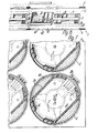
- This distance is only slight, for example about a third larger than the diameter of central fastening bolts 23 of the hot plates 2 formed by metric external thread shafts, one of which is arranged in the central axis of each hot plate 2 above the underside of the hot plate;
- the fastening bolt 23, which is usually screwed into a central internal thread eye of the plate base body 19, serves on the one hand to hold a cup-shaped cover 24 which closes the underside of the plate base body 19 within the ring flange 18 with the aid of a cover 24 placed on the fastening bolt and on the underside of the cover 24 adjacent nut 25 and on the other hand with its downwardly projecting section by more than the height of the plate base body 19 for fixing the hotplate in its installed position in a hob or the like.
- the bearing surface 15 or 17 goes to the side on which the two associated support members 5 and 6 are connected to one another by a connecting member 11, continuously via this connecting member, in such a way that the bearing surface 15 or 17 in this area continuously assumes an arc angle of approximately 80 °.
- the support surface 14 or 16 is formed by two identical arc sections which are spaced apart on both sides of the longitudinal center plane 17 and which are in each case parallel between the two Continuously go through side edges 13, 26 of the respective associated support member 5 or 6.
- the distance between the levels in which the bearing surfaces 14, 15 and 16, 17 lie is only slightly larger than the amount by which the respective fastening bolt 23 protrudes beyond the lower end face of the ring flange 18 of the associated hotplate.
- the largest diameter of the contact surfaces 14, 15 and 16, 17 is only slightly larger than the largest diameter of this end face.
- a circumferential centering surface 27, 28 and 29, 30, respectively, is assigned to each section of each support surface 14, 15 and 16, 17, and protrudes beyond the associated section of the support surface 14, 15 and 16, 17 by an amount that is approximately half corresponds to the height of the ring flange 18 and is slightly smaller than the amount by which the ring flange 18 projects beyond the underside of the diaphragm ring 20.
- Each circumferential centering surface 27 to 30 is formed by the inner circumferential surface of an arch web 31 or 32 projecting axially over the associated support surface 14 to 17, the height of which is approximately equal to the width of the respective support surface.
- the respective arch web or the associated circumferential centering surface is likewise interrupted, while it is also provided continuously where the bearing surface 15 or 17 passes over the gap.
- the essentially flat, shell-shaped support members are oriented in the same direction with respect to the central plane 8 on both sides of this central plane 8 or are inclined essentially parallel by a few degrees.
- the support members 5, 6 are provided on their outer and inner sides with upright ribs, which on the outer sides in each case vary from the level of the associated contact surface 15 or 17 which passes through the gap Reduce the height of the associated support member 5 or 6 in such a way that their free longitudinal edges, on the one hand, continuously merge into the outer circumferential surface of the associated arch web 32 and, on the other hand, their height decreases substantially to zero up to the free end face of the other arch web 31; an outer surface of the support members 5, 6 which is relatively smooth in the vertical direction is thereby achieved.
- the ribs decrease slightly in height in the opposite direction, in such a way that their associated end faces form parts of the contact surface 15 and 17, which is continuous over the respective gap 9 and 10.
- the part of this bearing surface 15, 17 which is delimited in an annular manner can be kept relatively narrow.
- Both the ribs 33 on the outer sides of the support member 5, 6 and the ribs 34 on their inner sides are formed in one piece with the respectively associated support member.
- the mutually facing and mutually or parallel to the longitudinal center plane 7 inner surfaces 35 of the connecting members 12 are offset substantially over their entire length relative to the associated outer side edges 13 of the supporting members 5, 6 to the outside so that the ends of these connecting members 12th with end sections 36 lying at an angle to them merge into the side edges 13 of the support members 5, 6 and connect the inner surfaces of the end sections 36 without gaps and gaps to the free longitudinal edges of the associated outermost ribs 34 on the inner sides of the support members 5, 6.
- the connecting links 12 are provided on their upper and lower sides, which are approximately at right angles to the central axes 21, 22, with groove-like depressions 37, which are symmetrical to their longitudinal central planes and are delimited at both ends, in such a way that the connecting links in the cross section through these depressions lie in the manner of DoppelT profiles are formed.
- Both the connecting links 12 and the connecting links 11 are elastically deformable to a limited extent in all directions transversely to their longitudinal central axes, as well as twisting about these longitudinal central axes, such that all the supporting links 5, 6 have a slight resilient mobility with respect to one another, by means of which they differ in tolerance differences can easily adjust the position of the hotplates to be stacked.
- the support members 5, 6 are essentially rigid or dimensionally stable.
- each support unit 3 can have two superimposed and with their undersides facing each other hot plates 2, which then lie centered with their ring flanges 18 on both sides of the support unit 3 on the support surfaces and whose fastening bolts 23 lie directly adjacent to one another in such a way that their end faces are each provided close to the underside of the cover of the opposite hotplate.
- the width of the gaps 9, 10 corresponds to the width of connection bodies 38, one of which is fastened to the underside of the cover 24 of the associated hotplate 2 with a radial arm-like holder and is provided with connecting terminals for the electrical connection of the hotplate.
- the two connecting bodies 38 of the two hotplates 2 engaging in a support unit 3 are inserted into the two diametrically opposite gaps 9, 10 of this support unit 3, such that the rotational position of the two hotplates 2 relative to the support unit 3 is inevitably exactly predetermined and fixed.
- the freely routed electrical lead wires leading from the resistance heating wires of the base plate body 19 to the connecting body 38 are also reliably protected against damage.
- Each intermediate layer 4 has a three-layer corrugated cardboard layer 39 made of two flat cover layers and a corrugated middle layer, which is provided with circular openings, which are adapted to the diameter of the plate base bodies 19 in the area of the cooking heating surfaces. These openings are provided next to one another in accordance with the stacking grid with an axial spacing which is only slightly larger than the outside diameter of the hotplates 2 in the region of the aperture rings 20.
- each corrugated cardboard layer 39 is provided with a solid cardboard box 40 which also passes through the openings and which is expediently covered on its underside with a thin protective layer made of a soft plastic film.
- each stack column is arranged in the same direction, ie. H.
- the support units 3 can be stacked one above the other in a space-saving manner and thus kept ready for reuse.
Landscapes
- Engineering & Computer Science (AREA)
- Mechanical Engineering (AREA)
- Warehouses Or Storage Devices (AREA)
- Baking, Grill, Roasting (AREA)
- Automatic Analysis And Handling Materials Therefor (AREA)
- Processing And Handling Of Plastics And Other Materials For Molding In General (AREA)
- Laminated Bodies (AREA)
- Medicines That Contain Protein Lipid Enzymes And Other Medicines (AREA)
- Furnace Charging Or Discharging (AREA)
- Cookers (AREA)
Priority Applications (1)
| Application Number | Priority Date | Filing Date | Title |
|---|---|---|---|
| AT85112064T ATE33968T1 (de) | 1984-10-31 | 1985-09-24 | Kochplatten-stapelbeilage. |
Applications Claiming Priority (2)
| Application Number | Priority Date | Filing Date | Title |
|---|---|---|---|
| DE3439777 | 1984-10-31 | ||
| DE19843439777 DE3439777A1 (de) | 1984-10-31 | 1984-10-31 | Kochplatten-stapelvorrichtung |
Publications (2)
| Publication Number | Publication Date |
|---|---|
| EP0180752A1 EP0180752A1 (de) | 1986-05-14 |
| EP0180752B1 true EP0180752B1 (de) | 1988-05-04 |
Family
ID=6249159
Family Applications (1)
| Application Number | Title | Priority Date | Filing Date |
|---|---|---|---|
| EP85112064A Expired EP0180752B1 (de) | 1984-10-31 | 1985-09-24 | Kochplatten-Stapelbeilage |
Country Status (11)
Families Citing this family (3)
| Publication number | Priority date | Publication date | Assignee | Title |
|---|---|---|---|---|
| DE3439777A1 (de) * | 1984-10-31 | 1986-05-07 | E.G.O. Elektro-Geräte Blanc u. Fischer, 7519 Oberderdingen | Kochplatten-stapelvorrichtung |
| DE3728541A1 (de) * | 1987-08-27 | 1989-03-09 | Ego Elektro Blanc & Fischer | Kochplatten-stapelhilfe sowie verfahren zu deren verwendung |
| DE3803806A1 (de) * | 1988-02-09 | 1989-08-17 | Ego Elektro Blanc & Fischer | Elektrokochplatte |
Family Cites Families (15)
| Publication number | Priority date | Publication date | Assignee | Title |
|---|---|---|---|---|
| US1757192A (en) * | 1927-05-16 | 1930-05-06 | American Can Co | Compartment can |
| US2687231A (en) * | 1950-11-22 | 1954-08-24 | Herbert H Somers | Stacking device |
| US3173574A (en) * | 1963-08-08 | 1965-03-16 | Gen Am Transport | Container stacking and covering devices |
| DE1190397B (de) * | 1963-08-21 | 1965-04-01 | Johann Waldherr O H G Appbau M | Zwischenring zum Stapeln von Behaeltern |
| DE1203177B (de) * | 1964-01-22 | 1965-10-14 | Heye Glasfabrik H | Verpackung fuer lagenweise stehend angeordnete Glasbehaelter, z. B. Flaschen |
| DE1756834A1 (de) * | 1968-07-20 | 1970-08-27 | Continental Gummi Werke Ag | Vorrichtung zum Stapeln ringfoermiger Gummi- oder Kunststoffartikel,insbesondere von Fahrzeugluftreifen |
| DK127538B (da) * | 1968-09-30 | 1973-11-26 | Van Der Osten Henning | Stableligt service. |
| FR2033223A1 (fr) * | 1969-01-07 | 1970-12-04 | Malinoise Const Mec | Support mutuel d'objets identiques empiles |
| JPS5912251B2 (ja) * | 1979-08-09 | 1984-03-22 | マルコン電子株式会社 | 電子浮子 |
| US4274538A (en) * | 1979-11-19 | 1981-06-23 | The Goodyear Tire & Rubber Company | Package and method of packaging for flat elongated material |
| US4415077A (en) * | 1981-02-26 | 1983-11-15 | Murphy Thomas V | Modular merchandise display tower |
| US4366905A (en) * | 1981-03-23 | 1983-01-04 | Syn-Trac Systems Inc. | Plastic material handling rack |
| DE8121160U1 (de) * | 1981-07-18 | 1981-10-15 | Franz Delbrouck Gmbh, 5750 Menden | Vorrichtung zum Stapeln von Flaschen |
| JPS5824610A (ja) * | 1981-07-31 | 1983-02-14 | 株式会社クボタ | 組込管の相互固定具 |
| DE3439777A1 (de) * | 1984-10-31 | 1986-05-07 | E.G.O. Elektro-Geräte Blanc u. Fischer, 7519 Oberderdingen | Kochplatten-stapelvorrichtung |
-
1984
- 1984-10-31 DE DE19843439777 patent/DE3439777A1/de not_active Withdrawn
-
1985
- 1985-09-24 EP EP85112064A patent/EP0180752B1/de not_active Expired
- 1985-09-24 AT AT85112064T patent/ATE33968T1/de not_active IP Right Cessation
- 1985-09-24 DE DE8585112064T patent/DE3562475D1/de not_active Expired
- 1985-10-02 AU AU48204/85A patent/AU583538B2/en not_active Ceased
- 1985-10-03 JP JP60219321A patent/JPS61114908A/ja active Pending
- 1985-10-10 US US06/786,215 patent/US4699269A/en not_active Expired - Fee Related
- 1985-10-23 ZA ZA858126A patent/ZA858126B/xx unknown
- 1985-10-28 YU YU1699/85A patent/YU43422B/xx unknown
- 1985-10-29 GR GR852599A patent/GR852599B/el unknown
- 1985-10-30 CA CA000494200A patent/CA1262114A/en not_active Expired
- 1985-10-30 ES ES548355A patent/ES8701662A1/es not_active Expired
-
1993
- 1993-03-11 JP JP1993016336U patent/JPH0638010Y2/ja not_active Expired - Fee Related
Also Published As
| Publication number | Publication date |
|---|---|
| AU4820485A (en) | 1986-05-08 |
| US4699269A (en) | 1987-10-13 |
| EP0180752A1 (de) | 1986-05-14 |
| JPH0572817U (ja) | 1993-10-05 |
| CA1262114A (en) | 1989-10-03 |
| YU43422B (en) | 1989-06-30 |
| AU583538B2 (en) | 1989-05-04 |
| ES548355A0 (es) | 1986-12-01 |
| ZA858126B (en) | 1986-06-25 |
| YU169985A (en) | 1988-02-29 |
| ATE33968T1 (de) | 1988-05-15 |
| ES8701662A1 (es) | 1986-12-01 |
| GR852599B (GUID-C5D7CC26-194C-43D0-91A1-9AE8C70A9BFF.html) | 1986-03-05 |
| JPS61114908A (ja) | 1986-06-02 |
| JPH0638010Y2 (ja) | 1994-10-05 |
| DE3439777A1 (de) | 1986-05-07 |
| DE3562475D1 (en) | 1988-06-09 |
Similar Documents
| Publication | Publication Date | Title |
|---|---|---|
| DE69109836T2 (de) | Modulartiger Förderer. | |
| EP3636559B1 (de) | Stapelbare kiste | |
| DE2244785B2 (de) | Aus Kunststoff geformte Tragvorrichtung für Behälter | |
| DE1286813B (de) | Befestigungsvorrichtung fuer Schrauben | |
| EP0106989A1 (de) | Korb zum Festhalten von Teilen auf einem Boden während ihrer Wärmebehandlung | |
| EP0212158B1 (de) | Profilabtastvorrichtung | |
| EP0207479B1 (de) | Transport- und Lagerpalette | |
| EP0180752B1 (de) | Kochplatten-Stapelbeilage | |
| EP0991829B1 (de) | Rosettenförmige haltevorrichtung für gerüstelemente | |
| EP0601494A1 (de) | Stirnwand aus Spritzgussmaterial für eine Wickelfolie | |
| EP0304752B1 (de) | Kochplatten-Stapelhilfe sowie Verfahren zu deren Verwendung | |
| EP3106421A1 (de) | Teleskopstange | |
| DE69002935T2 (de) | Plastisch geformte Trägerplatte zum Herstellen von Rollstützen, die mit anderen Platten desselben Types nebeneinander angeordnet, aufeinandergelegt und festgesetzt werden. | |
| EP0254283B1 (de) | Transporteinheit, bestehend aus einem tablettartigen Träger und auf dem Träger angeordneten Sektflaschen-drahtbügeln | |
| DE3527956A1 (de) | Stapelbares werkstuecktraegergestell | |
| EP0357817B1 (de) | Holzregal mit auf unterschiedlichen Höhen anbringbaren Einlegeböden | |
| AT393442B (de) | Karussellboden fuer eckschraenke | |
| DE202022103758U1 (de) | Verpackungssystem | |
| EP0630343B1 (de) | Stapel mit auf einer verpackung aufgereihten ring- oder ringscheibenförmigen teilen mit radialschlitz | |
| DE8702930U1 (de) | Flaschenkasten | |
| DE8912591U1 (de) | Traverse für den industriellen Halterungsbau | |
| DE3325989A1 (de) | Vorrichtung zur lagerung eines teils mit sehr grossen abmessungen | |
| DE2129587B2 (de) | Vorrichtung zum halten und kontaktieren von thermisch belasteten keramikwiderstaenden | |
| DE3405564C2 (de) | Transportvorrichtung | |
| AT527062B1 (de) | Mehrwegverpackungsvorrichtung für Pizzen |
Legal Events
| Date | Code | Title | Description |
|---|---|---|---|
| PUAI | Public reference made under article 153(3) epc to a published international application that has entered the european phase |
Free format text: ORIGINAL CODE: 0009012 |
|
| AK | Designated contracting states |
Kind code of ref document: A1 Designated state(s): AT CH DE FR GB IT LI NL SE |
|
| 17P | Request for examination filed |
Effective date: 19860523 |
|
| 17Q | First examination report despatched |
Effective date: 19870212 |
|
| GRAA | (expected) grant |
Free format text: ORIGINAL CODE: 0009210 |
|
| AK | Designated contracting states |
Kind code of ref document: B1 Designated state(s): AT CH DE FR GB IT LI NL SE |
|
| PG25 | Lapsed in a contracting state [announced via postgrant information from national office to epo] |
Ref country code: NL Effective date: 19880504 |
|
| REF | Corresponds to: |
Ref document number: 33968 Country of ref document: AT Date of ref document: 19880515 Kind code of ref document: T |
|
| REF | Corresponds to: |
Ref document number: 3562475 Country of ref document: DE Date of ref document: 19880609 |
|
| GBT | Gb: translation of ep patent filed (gb section 77(6)(a)/1977) | ||
| ITF | It: translation for a ep patent filed | ||
| ET | Fr: translation filed | ||
| NLV1 | Nl: lapsed or annulled due to failure to fulfill the requirements of art. 29p and 29m of the patents act | ||
| PLBE | No opposition filed within time limit |
Free format text: ORIGINAL CODE: 0009261 |
|
| STAA | Information on the status of an ep patent application or granted ep patent |
Free format text: STATUS: NO OPPOSITION FILED WITHIN TIME LIMIT |
|
| 26N | No opposition filed | ||
| ITTA | It: last paid annual fee | ||
| PGFP | Annual fee paid to national office [announced via postgrant information from national office to epo] |
Ref country code: GB Payment date: 19920911 Year of fee payment: 8 |
|
| PGFP | Annual fee paid to national office [announced via postgrant information from national office to epo] |
Ref country code: FR Payment date: 19920916 Year of fee payment: 8 |
|
| PGFP | Annual fee paid to national office [announced via postgrant information from national office to epo] |
Ref country code: SE Payment date: 19920923 Year of fee payment: 8 |
|
| PGFP | Annual fee paid to national office [announced via postgrant information from national office to epo] |
Ref country code: AT Payment date: 19920924 Year of fee payment: 8 |
|
| PGFP | Annual fee paid to national office [announced via postgrant information from national office to epo] |
Ref country code: CH Payment date: 19921019 Year of fee payment: 8 |
|
| PG25 | Lapsed in a contracting state [announced via postgrant information from national office to epo] |
Ref country code: GB Effective date: 19930924 Ref country code: AT Effective date: 19930924 |
|
| PG25 | Lapsed in a contracting state [announced via postgrant information from national office to epo] |
Ref country code: SE Effective date: 19930925 |
|
| PG25 | Lapsed in a contracting state [announced via postgrant information from national office to epo] |
Ref country code: LI Effective date: 19930930 Ref country code: CH Effective date: 19930930 |
|
| GBPC | Gb: european patent ceased through non-payment of renewal fee |
Effective date: 19930924 |
|
| PG25 | Lapsed in a contracting state [announced via postgrant information from national office to epo] |
Ref country code: FR Free format text: LAPSE BECAUSE OF NON-PAYMENT OF DUE FEES Effective date: 19940531 |
|
| REG | Reference to a national code |
Ref country code: CH Ref legal event code: PL |
|
| REG | Reference to a national code |
Ref country code: FR Ref legal event code: ST |
|
| EUG | Se: european patent has lapsed |
Ref document number: 85112064.2 Effective date: 19940410 |
|
| PGFP | Annual fee paid to national office [announced via postgrant information from national office to epo] |
Ref country code: DE Payment date: 19951120 Year of fee payment: 11 |
|
| PG25 | Lapsed in a contracting state [announced via postgrant information from national office to epo] |
Ref country code: DE Effective date: 19970603 |