EP0180728A2 - Abdichtvorrichtung für Verbindungen innenseitig zugänglicher Kammer- oder Rohrelemente - Google Patents
Abdichtvorrichtung für Verbindungen innenseitig zugänglicher Kammer- oder Rohrelemente Download PDFInfo
- Publication number
- EP0180728A2 EP0180728A2 EP85110500A EP85110500A EP0180728A2 EP 0180728 A2 EP0180728 A2 EP 0180728A2 EP 85110500 A EP85110500 A EP 85110500A EP 85110500 A EP85110500 A EP 85110500A EP 0180728 A2 EP0180728 A2 EP 0180728A2
- Authority
- EP
- European Patent Office
- Prior art keywords
- sealing device
- connecting piece
- sealing
- seal carrier
- face
- Prior art date
- Legal status (The legal status is an assumption and is not a legal conclusion. Google has not performed a legal analysis and makes no representation as to the accuracy of the status listed.)
- Granted
Links
Images
Classifications
-
- F—MECHANICAL ENGINEERING; LIGHTING; HEATING; WEAPONS; BLASTING
- F16—ENGINEERING ELEMENTS AND UNITS; GENERAL MEASURES FOR PRODUCING AND MAINTAINING EFFECTIVE FUNCTIONING OF MACHINES OR INSTALLATIONS; THERMAL INSULATION IN GENERAL
- F16L—PIPES; JOINTS OR FITTINGS FOR PIPES; SUPPORTS FOR PIPES, CABLES OR PROTECTIVE TUBING; MEANS FOR THERMAL INSULATION IN GENERAL
- F16L23/00—Flanged joints
- F16L23/16—Flanged joints characterised by the sealing means
- F16L23/18—Flanged joints characterised by the sealing means the sealing means being rings
-
- F—MECHANICAL ENGINEERING; LIGHTING; HEATING; WEAPONS; BLASTING
- F16—ENGINEERING ELEMENTS AND UNITS; GENERAL MEASURES FOR PRODUCING AND MAINTAINING EFFECTIVE FUNCTIONING OF MACHINES OR INSTALLATIONS; THERMAL INSULATION IN GENERAL
- F16J—PISTONS; CYLINDERS; SEALINGS
- F16J15/00—Sealings
- F16J15/16—Sealings between relatively-moving surfaces
- F16J15/32—Sealings between relatively-moving surfaces with elastic sealings, e.g. O-rings
- F16J15/3268—Mounting of sealing rings
-
- F—MECHANICAL ENGINEERING; LIGHTING; HEATING; WEAPONS; BLASTING
- F16—ENGINEERING ELEMENTS AND UNITS; GENERAL MEASURES FOR PRODUCING AND MAINTAINING EFFECTIVE FUNCTIONING OF MACHINES OR INSTALLATIONS; THERMAL INSULATION IN GENERAL
- F16L—PIPES; JOINTS OR FITTINGS FOR PIPES; SUPPORTS FOR PIPES, CABLES OR PROTECTIVE TUBING; MEANS FOR THERMAL INSULATION IN GENERAL
- F16L23/00—Flanged joints
- F16L23/16—Flanged joints characterised by the sealing means
Definitions
- the invention relates to a sealing device for connections inside chamber or tubular elements, which are provided at the end with connecting pieces, one of which has an end face and the other a circumferential recess, and are braced against each other, whereby the sealing surface of a sealing lip received in the recess of the one connecting piece bears against the flat end face of the other connecting piece.
- Such a sealing device has become known from US-PS 33 10 329.
- a lip seal of one element to be connected which is received in the recess of a first flange end face, is pressed in a sealing manner against the flat end face of the flange end of another element.
- the pressure required for the gas-tight seal is produced by a closure element, which is formed from a clamp comprising the flange beads, which firmly connects the elements to be connected to one another on the sealing surface of the lip seal by means of a tensioning device.
- the seal can only be replaced if the two elements to be connected are detached from one another.
- Such a sealing device is not suitable for installation for sealing pressure chambers or walk-in pipelines, which are permanently installed within an assembly housing or a building foundation, since the entire installation and the one for changing the sealing lip Chambers or pipes themselves must be separated from one another in order to obtain free access to the lip seal to be replaced. This is associated with considerable expense, loss of operating time for the chambers or pipes.
- the invention has for its object to improve a sealing device of the type mentioned so that the chamber connecting seal can be replaced without having to loosen the connectors themselves.
- the object is achieved in that the sealing lip is held in the inwardly open recess by a divided seal carrier which is detachably connected to the connecting piece.
- the advantage of the sealing device according to the invention is that the divided seal carrier can be removed in completely installed systems without dismantling the chamber or pipe system and the supply lines, after which the defective sealing lip can be removed from the recess in a freely accessible manner and replaced with a new one.
- the divided seal carrier can then be reassembled and at the same time ensures that the sealing lip lies firmly against the flat end face of the counterpart.
- a single-split seal carrier is sufficient, but it is advantageous to provide a multiple-split seal carrier, each of the sections of the seal carrier being expediently fastened to the connecting piece by a screw connection.
- the seal carrier For better assembly and disassembly of the seal carrier it is provided to divide it into longer and shorter sections, the shorter sections preferably having parallel or also converging end faces.
- End faces running in parallel result in a uniform gap between the sections, whereas the converging end faces result in a small gap in the assembled state and increasing in size during dismantling and thereby facilitating removal.
- the sections are prevented from becoming stuck due to dirt in the gaps.
- the flat end face of the connecting piece has a high quality edition.
- a connecting piece in the form of a flange end 2 which has an inwardly open recess 4, into which a sealing lip 1 is pressed firmly by the divided seal carrier 3 by means of the screw connection 5.
- the sealing surface of the sealing lip 1 abuts the support 9, which is applied to the end face 7 of a second flange end 8. Both flange ends are held together using the clamp 10.
Landscapes
- Engineering & Computer Science (AREA)
- General Engineering & Computer Science (AREA)
- Mechanical Engineering (AREA)
- Gasket Seals (AREA)
- Joints With Sleeves (AREA)
Abstract
Description
- Die Erfindung betrifft eine Abdichtvorrichtung für Verbindungen innenseitig zugänglicher Kammer- oder Rohrelemente, welche endseitig mit Verbindungsstücken, deren eines eine Stirnfläche und das andere eine stirnseitig umlaufende Ausnehmung aufweist, versehen und gegeneinander verspannt sind, wodurch die Dichtfläche einer in der Ausnehmung des einen Verbindungsstückes aufgenommenen Dichtlippe gegen die flächige Stirnfläche des anderen Verbindungsstückes anliegt.
- Eine solche Abdichtvorrichtung ist aus der US-PS 33 10 329 bekanntgeworden. Dort wird eine in der Ausnehmung einer ersten Flanschstirnfläche aufgenommene Lippendichtung des einen zu verbindenden Elementes gegen die flächige Stirnseite des Flanschendes eines anderen Elementes dichtend angedrückt. Der erforderliche Druck zur gasdichten Abdichtung wird durch ein Verschlußelement hergestellt, welches aus einer die Flanschwulste umfassenden Klammer gebildet wird, welche mittels einer Spannvorrichtung die zu verbindenden Elemente an der Dichtfläche der Lippendichtung fest miteinander verbindet. Ein Auswechseln der Dichtung kann jedoch nur dann erfolgen, wenn die beiden zu verbindenden Elemente voneinander gelöst werden.
- Eine solche Abdichtvorrichtung ist für den Einbau zur Abdichtung von Druckkammern oder begehbaren Rohrleitungen, welche innerhalb eines Montagegehäuses oder eines Baufundamentes fest installiert sind, nicht einsetzbar, da zum Wechseln der Dichtlippe die gesamte Installation sowie die Kammern bzw. Rohre selbst voneinander getrennt werden müssen, um einen freien Zugang zu der auszuwechselnden Lippendichtung zu erlangen. Dies ist mit erheblichem Auf wand, Betriebszeitverlust für die Kammern bzw. Rohre verbunden.
- Insbesondere ist z.B. bei bewohnbaren Druckkammern oder auch Drucksimulationsanlagen ein längerfristiger Aufenthalt von Menschen in diesen Druckkammern notwendig, so daß bei einem eventuell notwendigen Auswechseln der Dichtlippe ein wiederholtes Demontieren und eine anschließende Montage der einzelnen Komponenten unerwünscht ist, da die Bereitschaftszeit solcher Anlagen dadurch erheblich unterbrochen wird.
- Aus der DE-OS 23 25 910 ist eine Rohrkupplung bekanntgeworden, bei welcher zum Wechseln der Dichtung nach dem Lösen von Spannklammern ein mit einer Ringnut versehener Flanschring durch einen zurückschiebbaren Überwurfring freigelegt wird. Jedoch sind zum Wechseln der Dichtung die beiden Flanschringe um ein kurzes Stück auseinanderzurücken. Eine solche bekannte Kupplung ist demnach für die Abdichtung von begehbaren ortsfesten Druckkammern mit den gleichen aufwendigen Montagearbeiten verbunden.
- Der Erfindung liegt die Aufgabe zugrunde, eine Abdichtvorrichtung der genannten Art derart zu verbessern, daß die kammerverbindende Dichtung ausgewechselt werden kann, ohne die Verbindungsstücke selbst lösen zu müssen.
- Die Lösung der Aufgabe erfolgt dadurch, daß die Dichtlippe durch einen geteilten, mit dem Verbindungsstück lösbar verbundenen Dichtungsträger in der nach innen offenen Ausnehmung gehalten ist.
- Der Vorteil der erfindungsgemäßen Abdichtvorrichtung liegt darin, daß der geteilte Dichtungsträger bei fertig installierten Anlagen ohne Demontage des Kammer- bzw. Rohrsystems sowie der Versorgungsleitungen entfernt werden kann, wonach die defekte Dichtlippe frei zugänglich aus der Ausnehmung entfernt und durch eine neue ersetzt werden kann. Der geteilte Dichtungsträger kann anschließend wieder montiert werden und sorgt gleichzeitig für ein festes Anliegen der Dichtlippe an die flächige Stirnfläche des Gegenstückes.
- Je nach Kammergröße reicht ein einfach geteilter Dichtungsträger aus, jedoch ist vorteilhafterweise ein mehrfach geteilter Dichtungsträger vorzusehen, wobei jedes der Teilstücke des Dichtungsträgers zweckmäßigerweise durch eine Schraubverbindung an dem Verbindungsstück befestigt ist.
- Zur besseren Montage und Demontage des Dichtungsträgers ist vorgesehen, diesen in längere und kürzere Teilstücke aufzuteilen, wobei die kürzeren Teilstücke vorzugsweise parallel verlaufende oder auch nach außen konvergierende Endflächen aufweisen.
- Parallel verlaufende Endflächen ergeben einen gleichmäßigen Spalt zwischen den Teilstücken, die konvergierenden Endflächen dagegen einen im montierten Zustand geringen und bei der Demontage sich vergrößernden und dadurch die Entnahme erleichternden Spalt. Ein Festsetzen der Teilstücke durch Verschmutzungen der Spalte wird vermieden.
- In weiterer Ausgestaltung der Erfindung kann vorgesehen sein, daß die flächige Stirnseite des Verbindungsstückes eine qualitativ hochwertige Auflage aufweist.
- Ein Ausführungsbeispiel der Erfindung wird anhand der Zeichnung näher beschrieben.
- Es zeigen
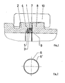
- Figur 1: eine Abdichtvorrichtung im Querschnitt der Verbindung,
- Figur 2: einen geteilten Dichtungsträger.
- In Figur 1 ist ein Verbindungsstück in Form eines Flanschendes 2 dargestellt, welches eine nach innen offene Ausnehmung 4 aufweist, in die eine Dichtlippe 1 durch den geteilten Dichtungsträger 3 mittels der Schraubverbindung 5 fest angedrückt wird. Die Dichtfläche der Dichtlippe 1 liegt an der Auflage 9 an, welche auf die Stirnfläche 7 eines zweiten Flanschendes 8 aufgebracht ist. Beide Flanschenden werden mit Hilfe der Klammer 10 zusammengehalten.
- In Figur 2 ist ein viergeteilter Dichtungsträger mit seinen Teilstücken 6, 6' unterschiedlicher Länge dargestellt.
Claims (8)
Applications Claiming Priority (2)
| Application Number | Priority Date | Filing Date | Title |
|---|---|---|---|
| DE19843440402 DE3440402A1 (de) | 1984-11-06 | 1984-11-06 | Abdichtvorrichtung fuer verbindungen innenseitig zugaenglicher kammer- oder rohrelemente |
| DE3440402 | 1984-11-06 |
Publications (3)
| Publication Number | Publication Date |
|---|---|
| EP0180728A2 true EP0180728A2 (de) | 1986-05-14 |
| EP0180728A3 EP0180728A3 (en) | 1987-10-07 |
| EP0180728B1 EP0180728B1 (de) | 1990-04-11 |
Family
ID=6249544
Family Applications (1)
| Application Number | Title | Priority Date | Filing Date |
|---|---|---|---|
| EP85110500A Expired - Lifetime EP0180728B1 (de) | 1984-11-06 | 1985-08-21 | Abdichtvorrichtung für Verbindungen innenseitig zugänglicher Kammer- oder Rohrelemente |
Country Status (4)
| Country | Link |
|---|---|
| EP (1) | EP0180728B1 (de) |
| DE (2) | DE3440402A1 (de) |
| FI (1) | FI81190C (de) |
| NO (1) | NO166893C (de) |
Cited By (2)
| Publication number | Priority date | Publication date | Assignee | Title |
|---|---|---|---|---|
| US5031755A (en) * | 1988-05-06 | 1991-07-16 | Sprink, Inc. | Pipe line termination system |
| GB2335904A (en) * | 1998-03-30 | 1999-10-06 | Asea Brown Boveri | End effector assembly for a robot |
Family Cites Families (13)
| Publication number | Priority date | Publication date | Assignee | Title |
|---|---|---|---|---|
| DE497070C (de) * | 1930-05-01 | Mannesmann Ag | Innenmuffenverbindung | |
| AT108310B (de) * | 1926-02-15 | 1927-12-27 | Spolka Akcyjna Ferrum | Mit Innendichtung versehene Rohrverbindung. |
| CH136459A (de) * | 1929-01-24 | 1929-11-15 | Int Siegwartbalken Ges In Luze | Rohrverbindung bei Zementröhren. |
| US2742177A (en) * | 1952-02-12 | 1956-04-17 | Hydro Blast Corp | Closure seal |
| US2775472A (en) * | 1952-11-14 | 1956-12-25 | Cicero C Brown | Sealing device for flanged joints |
| DE1805832U (de) * | 1959-10-21 | 1960-02-11 | Fritz Dickel | Abdichtungsvorrichtung an tueren u. dgl. |
| DE1193749B (de) * | 1961-10-09 | 1965-05-26 | Schoenebecker Brunnenfilter Ge | Hochdruckflanschverbindung fuer Rohrleitungen |
| GB984740A (en) * | 1961-11-28 | 1965-03-03 | Henry Crossley Packings Ltd | Improvements relating to seals for high pressure pipes or tubes |
| US3432175A (en) * | 1962-06-05 | 1969-03-11 | Kubota Iron & Machinery Works | Pipe joint which can be assembled from inside pipe |
| US3310329A (en) * | 1966-01-28 | 1967-03-21 | Gaston County Dyeing Mach | Pressure vessel and closure assembly therefor |
| FR1604783A (de) * | 1967-12-29 | 1972-01-31 | ||
| FR2088735A5 (de) * | 1970-04-23 | 1972-01-07 | Semt | |
| DE2325910A1 (de) * | 1973-05-22 | 1974-12-05 | Wilhelm Schulz | Rohrkupplung |
-
1984
- 1984-11-06 DE DE19843440402 patent/DE3440402A1/de active Granted
-
1985
- 1985-08-21 DE DE8585110500T patent/DE3577134D1/de not_active Expired - Fee Related
- 1985-08-21 EP EP85110500A patent/EP0180728B1/de not_active Expired - Lifetime
- 1985-09-09 FI FI853435A patent/FI81190C/fi not_active IP Right Cessation
- 1985-09-23 NO NO853731A patent/NO166893C/no unknown
Cited By (2)
| Publication number | Priority date | Publication date | Assignee | Title |
|---|---|---|---|---|
| US5031755A (en) * | 1988-05-06 | 1991-07-16 | Sprink, Inc. | Pipe line termination system |
| GB2335904A (en) * | 1998-03-30 | 1999-10-06 | Asea Brown Boveri | End effector assembly for a robot |
Also Published As
| Publication number | Publication date |
|---|---|
| FI853435L (fi) | 1986-05-07 |
| NO166893C (no) | 1991-09-11 |
| FI81190B (fi) | 1990-05-31 |
| NO166893B (no) | 1991-06-03 |
| FI81190C (fi) | 1990-09-10 |
| NO853731L (no) | 1986-05-07 |
| DE3577134D1 (de) | 1990-05-17 |
| DE3440402C2 (de) | 1988-12-15 |
| DE3440402A1 (de) | 1986-05-22 |
| EP0180728B1 (de) | 1990-04-11 |
| EP0180728A3 (en) | 1987-10-07 |
| FI853435A0 (fi) | 1985-09-09 |
Similar Documents
| Publication | Publication Date | Title |
|---|---|---|
| DE69714737T2 (de) | Modulare dichtungsanordnung für eine wandöffnung | |
| EP0671985B1 (de) | Presswerkzeug | |
| DE2339224A1 (de) | Vakuumdichtung | |
| DE2146126A1 (de) | ||
| EP0022248A1 (de) | Aus einzelnen Elementen zusammensetzbarer Hohlkörper | |
| DE69407777T2 (de) | Kuppelstück | |
| DE1296912B (de) | Zwischen zwei Flansche einer Rohrleitung einsetzbarer Absperrhahn mit flanschlosem Gehaeuse | |
| DE2607700C3 (de) | Verfahren zur Herstellung von Rohrleitungsanschlüssen o.dgl | |
| DE3443942C2 (de) | Rohrverbindung mit mindestens einem Abzweigstutzen | |
| EP0421253B1 (de) | Vorrichtung zum Verschliessen einer Kabelmuffe für das Verbinden und Abzweigen von Kabeln, insbesondere Fernmeldekabeln | |
| EP0100771B1 (de) | Vorrichtung zur selbstverriegelnden Verbindung von Tübbings für den Ausbau von Tunneln und Schächten | |
| EP0180728A2 (de) | Abdichtvorrichtung für Verbindungen innenseitig zugänglicher Kammer- oder Rohrelemente | |
| DE2047812A1 (de) | Rohrkupplung mit V förmigen Flanschen zur Verbindung von Rohren oder Schlauchen | |
| DE2513982C3 (de) | Rohrdichtung | |
| DE3223427A1 (de) | Kupplung zum gleichzeitigen verbinden mehrerer, eng benachbarter rohrleitungen | |
| DE939182C (de) | Rohrverbindung | |
| DE3102710A1 (de) | Dichtungsvorrichtung | |
| DE2141846A1 (de) | Rohrkupplung | |
| DE2641504A1 (de) | Winkelverstellbarer rohrkruemmer | |
| DE3317186A1 (de) | Verbindungselement zum kuppeln zweier flansche | |
| DE1083601B (de) | Vorrichtung zum Verbinden von rohrfoermigen Teilen | |
| DE3420135C2 (de) | ||
| DE2529138A1 (de) | Flansch-platten-anordnung, sowie verfahren zu deren herstellung | |
| DE19743185A1 (de) | Vorrichtung zum Anschließen von Rohrleitungen | |
| EP0340338B1 (de) | Rohrverbindung |
Legal Events
| Date | Code | Title | Description |
|---|---|---|---|
| PUAI | Public reference made under article 153(3) epc to a published international application that has entered the european phase |
Free format text: ORIGINAL CODE: 0009012 |
|
| 17P | Request for examination filed |
Effective date: 19850906 |
|
| AK | Designated contracting states |
Kind code of ref document: A2 Designated state(s): DE FR GB IT SE |
|
| PUAL | Search report despatched |
Free format text: ORIGINAL CODE: 0009013 |
|
| AK | Designated contracting states |
Kind code of ref document: A3 Designated state(s): DE FR GB IT SE |
|
| 17Q | First examination report despatched |
Effective date: 19880915 |
|
| GRAA | (expected) grant |
Free format text: ORIGINAL CODE: 0009210 |
|
| ITF | It: translation for a ep patent filed | ||
| AK | Designated contracting states |
Kind code of ref document: B1 Designated state(s): DE FR GB IT SE |
|
| REF | Corresponds to: |
Ref document number: 3577134 Country of ref document: DE Date of ref document: 19900517 |
|
| GBT | Gb: translation of ep patent filed (gb section 77(6)(a)/1977) | ||
| ET | Fr: translation filed | ||
| PGFP | Annual fee paid to national office [announced via postgrant information from national office to epo] |
Ref country code: SE Payment date: 19900815 Year of fee payment: 6 |
|
| PLBE | No opposition filed within time limit |
Free format text: ORIGINAL CODE: 0009261 |
|
| STAA | Information on the status of an ep patent application or granted ep patent |
Free format text: STATUS: NO OPPOSITION FILED WITHIN TIME LIMIT |
|
| 26N | No opposition filed | ||
| PGFP | Annual fee paid to national office [announced via postgrant information from national office to epo] |
Ref country code: GB Payment date: 19910723 Year of fee payment: 7 |
|
| PGFP | Annual fee paid to national office [announced via postgrant information from national office to epo] |
Ref country code: FR Payment date: 19910807 Year of fee payment: 7 |
|
| PG25 | Lapsed in a contracting state [announced via postgrant information from national office to epo] |
Ref country code: SE Effective date: 19910822 |
|
| ITTA | It: last paid annual fee | ||
| PGFP | Annual fee paid to national office [announced via postgrant information from national office to epo] |
Ref country code: DE Payment date: 19910918 Year of fee payment: 7 |
|
| PG25 | Lapsed in a contracting state [announced via postgrant information from national office to epo] |
Ref country code: GB Effective date: 19920821 |
|
| GBPC | Gb: european patent ceased through non-payment of renewal fee |
Effective date: 19920821 |
|
| PG25 | Lapsed in a contracting state [announced via postgrant information from national office to epo] |
Ref country code: FR Effective date: 19930430 |
|
| PG25 | Lapsed in a contracting state [announced via postgrant information from national office to epo] |
Ref country code: DE Effective date: 19930501 |
|
| REG | Reference to a national code |
Ref country code: FR Ref legal event code: ST |
|
| EUG | Se: european patent has lapsed |
Ref document number: 85110500.7 Effective date: 19920306 |