EP0180535A1 - Koaxiale Verbindungen - Google Patents
Koaxiale Verbindungen Download PDFInfo
- Publication number
- EP0180535A1 EP0180535A1 EP85630169A EP85630169A EP0180535A1 EP 0180535 A1 EP0180535 A1 EP 0180535A1 EP 85630169 A EP85630169 A EP 85630169A EP 85630169 A EP85630169 A EP 85630169A EP 0180535 A1 EP0180535 A1 EP 0180535A1
- Authority
- EP
- European Patent Office
- Prior art keywords
- sleeve
- ribs
- cylindrical member
- bushing
- joint according
- Prior art date
- Legal status (The legal status is an assumption and is not a legal conclusion. Google has not performed a legal analysis and makes no representation as to the accuracy of the status listed.)
- Ceased
Links
- 239000000463 material Substances 0.000 claims description 4
- 230000003247 decreasing effect Effects 0.000 claims description 3
- 229920003023 plastic Polymers 0.000 claims description 3
- 239000004033 plastic Substances 0.000 claims description 3
- 238000010276 construction Methods 0.000 description 4
- 238000003780 insertion Methods 0.000 description 3
- 230000037431 insertion Effects 0.000 description 3
- 230000004048 modification Effects 0.000 description 3
- 238000012986 modification Methods 0.000 description 3
- 238000004519 manufacturing process Methods 0.000 description 2
- 230000000694 effects Effects 0.000 description 1
- 239000002184 metal Substances 0.000 description 1
- 238000000034 method Methods 0.000 description 1
Images
Classifications
-
- F—MECHANICAL ENGINEERING; LIGHTING; HEATING; WEAPONS; BLASTING
- F16—ENGINEERING ELEMENTS AND UNITS; GENERAL MEASURES FOR PRODUCING AND MAINTAINING EFFECTIVE FUNCTIONING OF MACHINES OR INSTALLATIONS; THERMAL INSULATION IN GENERAL
- F16C—SHAFTS; FLEXIBLE SHAFTS; ELEMENTS OR CRANKSHAFT MECHANISMS; ROTARY BODIES OTHER THAN GEARING ELEMENTS; BEARINGS
- F16C27/00—Elastic or yielding bearings or bearing supports, for exclusively rotary movement
- F16C27/02—Sliding-contact bearings
-
- F—MECHANICAL ENGINEERING; LIGHTING; HEATING; WEAPONS; BLASTING
- F16—ENGINEERING ELEMENTS AND UNITS; GENERAL MEASURES FOR PRODUCING AND MAINTAINING EFFECTIVE FUNCTIONING OF MACHINES OR INSTALLATIONS; THERMAL INSULATION IN GENERAL
- F16B—DEVICES FOR FASTENING OR SECURING CONSTRUCTIONAL ELEMENTS OR MACHINE PARTS TOGETHER, e.g. NAILS, BOLTS, CIRCLIPS, CLAMPS, CLIPS OR WEDGES; JOINTS OR JOINTING
- F16B7/00—Connections of rods or tubes, e.g. of non-circular section, mutually, including resilient connections
- F16B7/10—Telescoping systems
-
- F—MECHANICAL ENGINEERING; LIGHTING; HEATING; WEAPONS; BLASTING
- F16—ENGINEERING ELEMENTS AND UNITS; GENERAL MEASURES FOR PRODUCING AND MAINTAINING EFFECTIVE FUNCTIONING OF MACHINES OR INSTALLATIONS; THERMAL INSULATION IN GENERAL
- F16C—SHAFTS; FLEXIBLE SHAFTS; ELEMENTS OR CRANKSHAFT MECHANISMS; ROTARY BODIES OTHER THAN GEARING ELEMENTS; BEARINGS
- F16C17/00—Sliding-contact bearings for exclusively rotary movement
- F16C17/12—Sliding-contact bearings for exclusively rotary movement characterised by features not related to the direction of the load
- F16C17/18—Sliding-contact bearings for exclusively rotary movement characterised by features not related to the direction of the load with floating brasses or brushing, rotatable at a reduced speed
-
- F—MECHANICAL ENGINEERING; LIGHTING; HEATING; WEAPONS; BLASTING
- F16—ENGINEERING ELEMENTS AND UNITS; GENERAL MEASURES FOR PRODUCING AND MAINTAINING EFFECTIVE FUNCTIONING OF MACHINES OR INSTALLATIONS; THERMAL INSULATION IN GENERAL
- F16D—COUPLINGS FOR TRANSMITTING ROTATION; CLUTCHES; BRAKES
- F16D1/00—Couplings for rigidly connecting two coaxial shafts or other movable machine elements
- F16D1/06—Couplings for rigidly connecting two coaxial shafts or other movable machine elements for attachment of a member on a shaft or on a shaft-end
- F16D1/08—Couplings for rigidly connecting two coaxial shafts or other movable machine elements for attachment of a member on a shaft or on a shaft-end with clamping hub; with hub and longitudinal key
- F16D1/0829—Couplings for rigidly connecting two coaxial shafts or other movable machine elements for attachment of a member on a shaft or on a shaft-end with clamping hub; with hub and longitudinal key with radial loading of both hub and shaft by an intermediate ring or sleeve
- F16D1/0835—Couplings for rigidly connecting two coaxial shafts or other movable machine elements for attachment of a member on a shaft or on a shaft-end with clamping hub; with hub and longitudinal key with radial loading of both hub and shaft by an intermediate ring or sleeve due to the elasticity of the ring or sleeve
-
- Y—GENERAL TAGGING OF NEW TECHNOLOGICAL DEVELOPMENTS; GENERAL TAGGING OF CROSS-SECTIONAL TECHNOLOGIES SPANNING OVER SEVERAL SECTIONS OF THE IPC; TECHNICAL SUBJECTS COVERED BY FORMER USPC CROSS-REFERENCE ART COLLECTIONS [XRACs] AND DIGESTS
- Y10—TECHNICAL SUBJECTS COVERED BY FORMER USPC
- Y10T—TECHNICAL SUBJECTS COVERED BY FORMER US CLASSIFICATION
- Y10T403/00—Joints and connections
- Y10T403/45—Flexibly connected rigid members
- Y10T403/451—Rigid sleeve encompasses flexible bushing
-
- Y—GENERAL TAGGING OF NEW TECHNOLOGICAL DEVELOPMENTS; GENERAL TAGGING OF CROSS-SECTIONAL TECHNOLOGIES SPANNING OVER SEVERAL SECTIONS OF THE IPC; TECHNICAL SUBJECTS COVERED BY FORMER USPC CROSS-REFERENCE ART COLLECTIONS [XRACs] AND DIGESTS
- Y10—TECHNICAL SUBJECTS COVERED BY FORMER USPC
- Y10T—TECHNICAL SUBJECTS COVERED BY FORMER US CLASSIFICATION
- Y10T403/00—Joints and connections
- Y10T403/45—Flexibly connected rigid members
- Y10T403/455—Elastomer interposed between radially spaced members
- Y10T403/458—Composite bushing with elastomeric component
-
- Y—GENERAL TAGGING OF NEW TECHNOLOGICAL DEVELOPMENTS; GENERAL TAGGING OF CROSS-SECTIONAL TECHNOLOGIES SPANNING OVER SEVERAL SECTIONS OF THE IPC; TECHNICAL SUBJECTS COVERED BY FORMER USPC CROSS-REFERENCE ART COLLECTIONS [XRACs] AND DIGESTS
- Y10—TECHNICAL SUBJECTS COVERED BY FORMER USPC
- Y10T—TECHNICAL SUBJECTS COVERED BY FORMER US CLASSIFICATION
- Y10T403/00—Joints and connections
- Y10T403/55—Member ends joined by inserted section
- Y10T403/559—Fluted or splined section
-
- Y—GENERAL TAGGING OF NEW TECHNOLOGICAL DEVELOPMENTS; GENERAL TAGGING OF CROSS-SECTIONAL TECHNOLOGIES SPANNING OVER SEVERAL SECTIONS OF THE IPC; TECHNICAL SUBJECTS COVERED BY FORMER USPC CROSS-REFERENCE ART COLLECTIONS [XRACs] AND DIGESTS
- Y10—TECHNICAL SUBJECTS COVERED BY FORMER USPC
- Y10T—TECHNICAL SUBJECTS COVERED BY FORMER US CLASSIFICATION
- Y10T403/00—Joints and connections
- Y10T403/70—Interfitted members
- Y10T403/7047—Radially interposed shim or bushing
- Y10T403/7061—Resilient
Definitions
- the present invention relates to coaxial joints, and particularly to joints for joining an inner cylindrical member to an outer cylindrical member while permitting rotary and/or linear movements between the two members.
- Coaxial joints of the foregoing type commonly include a bushing disposed between the two cylindrical members, which bushing is non-rotatably received within the outer cylindrical member and includes a bore for rotatably receiving the inner cylindrical member.
- Such bushings are usually made of hard plastic material and are forcibly inserted into the outer cylindrical member so as to provide a firm, non-rotatable gripping thereof.
- the dimensions of the bore through the bushing are very critical in order to prevent any significant play when the inner cylindrical member is rotatably received within it. Therefore the conventional practice is to ream the final critical dimensions of the bore after the bushing has been forcibly introduced into the outer cylindrical member so as to compensate for any distortions of the bushing during this process. However, this reaming step adds substantially to the production costs of such a joint.
- An object of the present invention is to provide a coaxial joint having a bushing of a construction such that the distortion of the bushing bore is substantially reduced or eliminated during the insertion of the.bushing into the outer cylindrical member, so as to obviate the need for the usual reaming step.
- a coaxial joint for joining an inner cylindrical member to an outer cylindrical member by means of a bushing disposed between the two cylindrical members, characterized in that the bushing includes: an outer sleeve non-rotatably received within the outer cylindrical member; an inner sleeve formed with a central bore for receiving the inner cylindrical member; a first group of longitudinally-extending, circumferentially-spaced ribs formed between the inner and outer sleeves; and a second group of longitudinally-extending, circumferentially-spaced ribs formed in staggered relationship with the first group of ribs in the outer face of the outer sleeve and effective, when the outer sleeve is forcibly received within the outer cylindrical member, to distort inwardly the portions of the outer sleeve between the first group of ribs, and thereby to minimize the distortion of the inner sleeve.
- Such a bushing may be produced with an originally-formed bore having the critical dimensions required to rotat
- the bushing includes two sections, namely an inner section comprising the inner' sleeve, and an outer section comprising the outer sleeve and the two groups of ribs formed on its inner and outer faces, respectively. It is contemplated, however, that the bushing can be made as a single unit integrally formed with the inner and outer sleeves and the two groups of ribs.
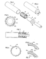
- the joint illustrated in Figs. 1-3 is used for joining an inner cylindrical member 2 to an outer cylindrical member 3 such as to permit rotation and/or linear movment of member 2 with a minimum of play with respect to member 3.
- One application for such a joint is in rotatably mounting a chair seat to a chair base, wherein cylindrical member 3 is fixed to the chair base and cylindrical member 2 carries the chair seat so as to permit rotation of the seat with respect to the base.
- the rotatable mounting of member 2 with respect to member 3 is effected by the use of a bushing constituted of two coaxial sleeves, namely an outer sleeve 4 and an inner sleeve 5.
- the outer sleeve 4 is forcibly introduced into the outer cylindrical member 3 so as to be tightly and non-rotatably pressed-fitted therein; and the inner sleeve 5 is similarly forcibly introduced into the outer sleeve 4 so as to be tightly and non-rotatably press-fitted therein.
- the inner cylindrical member 2 is received within the inner sleeve 5 so as to be rotatable therein with very little play, as will be described more particularly below.
- the outer bushing sleeve 4 is formed with two groups of longitudinally-extending, circumferentially-spaced ribs 41, 42.
- the first group of ribs 41 are formed on the inner face of the sleeve, and a second group of ribs 42 are formed on the outer face of the sleeve in staggered relationship with respect to the inner ribs 41, such that each inner rib 41 is disposed mid-way between each pair of adjacent outer ribs 42.
- the outer faces of the outer ribs 42 are substantially flat and lie along a circle having a diameter slightly larger than the inner diameter of the outer cylindrical member 3 so as to permit the bushing sleeve 4 to be forcibly introduced into member 3 with a tight, non-rotatably press-fit; and the inner faces of the inner ribs 41 are also substantially flat and lie along a circle which is slightly smaller than the outer diameter of the inner bushing sleeve 5 so as * to permit that bushing sleeve to be forcibly introduced into bushing sleeve 4 with a tight, non-rotatable press-fit.
- the inner bushing sleeve 5 is formed with a central bore 51 having a diameter just slightly larger than the outer diameter of the inner cylindrical member 2 so as to permit the latter member to be rotatably received within the bore with a minimum of play.
- the outer end of sleeve 5 is formed with an annular flange 52 which limits against the end of the outer cylindrical member 3 for fixing the position of bushing sleeve 5 within that member.
- Fig. 3 illustrates the assembled condition of the rotatable joint.
- the inner bushing sleeve 5 is first pressed into the outer bushing sleeve 4 until flange 52 of sleeve 5 limits against the edge of the outer sleeve 4.
- the engagement of the ribs 41 with the outer face of the inner sleeve 5 apply outward forces to the portions of the outer sleeve between its outer ribs 42, tending to distort these portions outwardly, so that the inner ribs 41 firmly and non-rotatably grip the inner sleeve 5.
- the outer sleeve 4, with the inner sleeve 5 firmly gripped therein, is then forcibly introduced into the outer cylindrical member 3 until flange 52 of the inner sleeve 5 limits against the end of member 3.
- the distortion of the inner bushing sleeve 5 is minimal so that bore 51 formed in the inner sleeve retains substantially its original dimensions to accomodate the inner cylindrical member 2 for rotation with substantially no play. Accordingly, the inner sleeve 5 may be produced with the required critically-dimensioned bore 51 for accomodating member 2 in a rotatable, substantially play-free manner and does not require a reaming operation to be performed after the bushing sleeves have been forcibly introduced into the outer cylindrical member 3 as in the previous constructions.
- inner bushing sleeve 5 may first be inserted into the outer sleeve 4, and then both applied to the outer cylindrical member 3; also, that flange 52 on the inner sleeve 5 could be omitted.
- the two bushing sleeves 4 and 5 are preferably produced as separate units and assembled together as described above. It is contemplated, however, that the two sleeves 4 and 5 may be formed as a single unit. This is shown in Fig. 5 wherein it will be seen that the bushing is constituted of a single unit integrally formed with the outer sleeve 104, the inner sleeve 105, the inner longitudinally-extending ribs 141 and the outer longitudinally-extending ribs 142.
- the provision of the inner and outer ribs (41, 42) on the outer bushing sleeve 4 inparts a flexibility to the sleeve, which flexibility accomodates the forces by distorting the outer sleeve, and thereby minimizes the distortion of the inner sleeve 5 when the two bushing sleeves are forcibly introduced into the outer cylindrical member 3.
- This flexibility depends on a number of factors, including the thickness of the outer sleeve 4, and the spacing of the longitudinally-extending ribs 41 and 42.
- Another factor affecting the flexibility of the outer sleeve 4 is the configuration of the ribs 41, 42. In the embodiment illustrated in Fig. 4 (and also in Fig. 5) the ribs are shown as being of substantially rectangular cross-section.
- Fig. 6 illustrates a variation wherein the ribs, therein designated 241 and 242, are of trapezoidal cross-section decreasing in width in the direction away from the outer sleeve 204, thereby decreasing the flexibility and distortion of the outer bushing sleeve; and Fig. 7 illustrates a modification wherein the ribs, therein designated 341 and 342, are of trapezoidal cross-section but increasing in width in the direction away from the bushing sleeve 304, thereby increasing the flexibility and distortion of the outer bushing sleeve.
- both bushing sleeves (4 and 5) are preferably of hard plastics material, but could be of other materials, such as metal.
Landscapes
- Engineering & Computer Science (AREA)
- General Engineering & Computer Science (AREA)
- Mechanical Engineering (AREA)
- Mutual Connection Of Rods And Tubes (AREA)
Applications Claiming Priority (2)
| Application Number | Priority Date | Filing Date | Title |
|---|---|---|---|
| IL73328A IL73328A (en) | 1984-10-26 | 1984-10-26 | Rotatable joint with coaxially assembled parts |
| IL73328 | 1984-10-26 |
Publications (1)
| Publication Number | Publication Date |
|---|---|
| EP0180535A1 true EP0180535A1 (de) | 1986-05-07 |
Family
ID=11055440
Family Applications (1)
| Application Number | Title | Priority Date | Filing Date |
|---|---|---|---|
| EP85630169A Ceased EP0180535A1 (de) | 1984-10-26 | 1985-10-21 | Koaxiale Verbindungen |
Country Status (3)
| Country | Link |
|---|---|
| US (1) | US4636106A (de) |
| EP (1) | EP0180535A1 (de) |
| IL (1) | IL73328A (de) |
Cited By (10)
| Publication number | Priority date | Publication date | Assignee | Title |
|---|---|---|---|---|
| GB2189557A (en) * | 1986-04-22 | 1987-10-28 | Eurocastors Limited | Improvements in bearings for wheels |
| EP0246833A2 (de) * | 1986-05-20 | 1987-11-25 | BLI (Overseas) Limited | Verbindungselement für rohrförmige Teile |
| GB2182104B (en) * | 1985-10-31 | 1989-12-13 | Black & Decker Inc | Improvements in or relating to bearing assemblies |
| EP0361589A1 (de) * | 1988-09-22 | 1990-04-04 | Koninklijke Philips Electronics N.V. | Laterale bipolare Transistoranordnungen mit isolierter Steuerelektrode mit geteilter Anode |
| FR2668244A1 (fr) * | 1990-10-18 | 1992-04-24 | Ahrend Groep Nv | Moyens pour relier ensemble deux cadres. |
| US5390463A (en) * | 1993-11-24 | 1995-02-21 | Penn Fabrication (U.S.A.) Inc. | Modular truss structure |
| DE102008049940A1 (de) * | 2008-10-02 | 2010-04-08 | Zf Friedrichshafen Ag | Hohlwellen-Verbindungseinrichtung |
| EP1972523A3 (de) * | 2007-03-21 | 2011-05-04 | GM Global Technology Operations, Inc. | Verstellbare Lenksäule mit einer Hülse und Verfahren zur Formung eines Füllstoffs mit einer Hülse |
| ITUB20159607A1 (it) * | 2015-12-29 | 2016-03-29 | Remo Italiano S R L | Manicotto per remo e remo comprendente un tale manicotto. |
| WO2017014709A1 (en) * | 2015-07-23 | 2017-01-26 | Ford Otomotiv Sanayi Anonim Sirketi | A spring bracket |
Families Citing this family (78)
| Publication number | Priority date | Publication date | Assignee | Title |
|---|---|---|---|---|
| US4752269A (en) * | 1986-05-09 | 1988-06-21 | Jonathan Feinstein | Reconfigurable, interchangeable and interlocking playthings, blocks or construction pieces |
| CA1313384C (en) * | 1986-08-18 | 1993-02-02 | Yoshiyuki Suzuki | Guard attachment/removal structure in baby carriage |
| US4790683A (en) * | 1987-10-05 | 1988-12-13 | Cramer Jr Arthur A | Tolerance ring and shim and method of use |
| US4895475A (en) * | 1988-02-23 | 1990-01-23 | Carter Donald L | Assembly of cylinder and shaft with low stress coupling and method of making same |
| US4960009A (en) * | 1988-06-02 | 1990-10-02 | Dana Corporation | Noise and vibration damper for a transmission shift lever |
| US5551722A (en) * | 1988-10-26 | 1996-09-03 | Maclean-Fogg Company | Vehicle suspension link |
| US4997307A (en) * | 1989-11-27 | 1991-03-05 | Schmanski Donald W | Removable snow pole insert |
| US5061000A (en) * | 1989-12-20 | 1991-10-29 | Vix Design Products, Inc. | Rack for pickup truck |
| DE69221296T2 (de) * | 1991-05-10 | 1997-11-20 | Poletech Systems Ltd | Pfosteneinrichtung |
| US5467664A (en) * | 1993-07-26 | 1995-11-21 | Black River Manufacturing, Inc. | Noise abating vehicle transmission shift lever |
| US5501541A (en) * | 1993-08-09 | 1996-03-26 | Gomes; Daniel | Flexible coupling device |
| US5613794A (en) * | 1994-08-16 | 1997-03-25 | Hong Kong (Link) Bicycles Ltd. | Bi-material tubing and method of making same |
| US5565251A (en) * | 1994-10-21 | 1996-10-15 | Btr Antivibration Systems, Inc. | Stabilizer bar bushing with ultra high molecular weight polyethylene lining method of manufacture |
| JPH08245074A (ja) * | 1995-03-08 | 1996-09-24 | Murata Mach Ltd | トラバース装置 |
| US5647638A (en) * | 1995-06-07 | 1997-07-15 | Haworth, Inc. | Height-adjustable chair arm assembly |
| FR2737173B1 (fr) * | 1995-07-26 | 1997-10-10 | Nacam | Colonne de direction reglable en profondeur, avec dispositif de guidage |
| US5832548A (en) * | 1996-01-23 | 1998-11-10 | Cosco, Inc. | Snap-in frame connector |
| US5755431A (en) * | 1996-03-18 | 1998-05-26 | Williams; Robert M. | Post assembly and mounting fitting therefor |
| DE19653777A1 (de) * | 1996-12-21 | 2001-01-25 | Kolbenschmidt Ag | Einbaufertiges Gelenk sowie Verfahren und Vorrichtung zu seiner Herstellung |
| JP3811608B2 (ja) * | 2000-10-03 | 2006-08-23 | 株式会社ジェイテクト | チルトステアリング装置 |
| US6598923B2 (en) * | 2000-11-22 | 2003-07-29 | Alcoa Inc. | Joint structure and method for making a joint structure |
| US7007386B1 (en) | 2002-12-20 | 2006-03-07 | General Sullivan Group, Inc. | Light duty bearing assembly |
| US6792712B1 (en) * | 2003-04-29 | 2004-09-21 | Susan M. Houg-Blymyer | Fishing line leader holder system |
| US7101108B1 (en) * | 2003-12-22 | 2006-09-05 | Lung-Tang Chuang | Collar for taking hold of fixation piece of window shade rod |
| US20050200111A1 (en) * | 2004-03-11 | 2005-09-15 | Cymbal William D. | Multi piece bearing for telescoping steering column assembly |
| US7516985B2 (en) * | 2004-03-11 | 2009-04-14 | Delphi Technologies, Inc. | Multi piece bearing for telescoping steering column assembly |
| US20060046858A1 (en) * | 2004-08-26 | 2006-03-02 | Ronald Brissette | Driveshaft assembly with torque ring coupling |
| US7534383B2 (en) * | 2004-12-08 | 2009-05-19 | Delphi Technologies, Inc. | Method of supporting a bushing against radial movement relative to a steering column jacket with a filler material |
| JP4684735B2 (ja) * | 2005-04-28 | 2011-05-18 | Hoya株式会社 | 移動機構 |
| GB0511494D0 (en) * | 2005-06-06 | 2005-07-13 | Rencol Tolerance Rings Ltd | Force limiting assembly |
| US20070080593A1 (en) * | 2005-10-07 | 2007-04-12 | O'donnell Steven B | Bearing sleeve |
| DE102006017305A1 (de) * | 2006-04-12 | 2007-10-18 | Gerd Eisenblätter Gmbh | Befestigungssystem, Befestigungsadapter und Befestigungsverfahren |
| US7857151B2 (en) * | 2007-01-04 | 2010-12-28 | Ex-Cell Home Fashions, Inc. | Tension rod assembly with adaptor |
| US7607855B2 (en) * | 2007-01-16 | 2009-10-27 | Hsin-Yuan Lai | Positioning sleeve for a telescopic rod |
| US8602180B2 (en) * | 2008-07-31 | 2013-12-10 | Powerbrace Corporation | Railroad freight car brake beam assembly |
| JP4831499B2 (ja) * | 2009-02-09 | 2011-12-07 | 株式会社デンソー | スプリングダンパ及びこれを用いたアクセル装置 |
| US8282285B2 (en) * | 2009-05-04 | 2012-10-09 | Pratt & Whitney Canada Corp. | Bearing support |
| US9833098B2 (en) | 2009-07-14 | 2017-12-05 | Loominocity, Inc. | Architecture for routing multi-channel commands via a tree column |
| US10993572B2 (en) | 2009-07-14 | 2021-05-04 | Belgravia Wood Limited | Power pole for artificial tree apparatus with axial electrical connectors |
| US11013356B2 (en) | 2009-07-14 | 2021-05-25 | Belgravia Wood Limited | Power pole for artificial tree apparatus with axial electrical connectors |
| US8651166B1 (en) * | 2010-05-04 | 2014-02-18 | Joseph J. Daniels | Adjustable roller shade |
| RU2556499C2 (ru) * | 2010-08-31 | 2015-07-10 | Киекерт Акциенгезельшафт | Исполнительный механизм для автотехнического применения |
| US8568015B2 (en) | 2010-09-23 | 2013-10-29 | Willis Electric Co., Ltd. | Decorative light string for artificial lighted tree |
| US8851305B2 (en) | 2010-12-17 | 2014-10-07 | Zenith Products Corporation | Unidirectional tension rod mechanism |
| US8960456B2 (en) | 2010-12-17 | 2015-02-24 | Zenith Products Corporation | Molded tension rod mechanism with single lock nut |
| US8827587B2 (en) | 2010-12-17 | 2014-09-09 | Zenith Products Corporation | Tension rod mechanism with opposing threads |
| US8689516B2 (en) * | 2011-03-17 | 2014-04-08 | Zephyros, Inc. | Bonding assembly |
| US8298633B1 (en) | 2011-05-20 | 2012-10-30 | Willis Electric Co., Ltd. | Multi-positional, locking artificial tree trunk |
| KR101090775B1 (ko) * | 2011-06-03 | 2011-12-08 | 고영균 | 레버형 손잡이 및 레버형 손잡이용 로크 부재 |
| JP2013002498A (ja) * | 2011-06-14 | 2013-01-07 | Sony Corp | 保持部材 |
| JP5440559B2 (ja) * | 2011-06-30 | 2014-03-12 | 株式会社ニコン | レンズ鏡筒および撮像装置 |
| US8863416B2 (en) | 2011-10-28 | 2014-10-21 | Polygroup Macau Limited (Bvi) | Powered tree construction |
| US8505129B2 (en) | 2011-11-11 | 2013-08-13 | Ex-Cell Home Fashions, Inc. | Rod with twist-end tension assembly |
| US8869999B2 (en) * | 2012-02-06 | 2014-10-28 | Zenith Products Corporation | Curtain rod end cap and cover |
| GB201203153D0 (en) * | 2012-02-23 | 2012-04-11 | Louver Lite Ltd | Roller tube |
| US9271592B2 (en) | 2012-11-14 | 2016-03-01 | Zenith Products Corporation | Adjustable tension-mounted curved rod assembly |
| US8978228B2 (en) | 2012-11-14 | 2015-03-17 | Zenith Products Corporation | Adjustable rod assembly |
| US9107529B2 (en) | 2012-11-14 | 2015-08-18 | Zenith Products Corporation | Adjustable tension-mounted curved rod assembly |
| US9894949B1 (en) | 2013-11-27 | 2018-02-20 | Willis Electric Co., Ltd. | Lighted artificial tree with improved electrical connections |
| USD746667S1 (en) | 2014-01-24 | 2016-01-05 | Zenith Products Corporation | Pair of end caps for a curtain rod |
| US9883566B1 (en) | 2014-05-01 | 2018-01-30 | Willis Electric Co., Ltd. | Control of modular lighted artificial trees |
| US9839315B2 (en) | 2015-03-27 | 2017-12-12 | Polygroup Macau Limited (Bvi) | Multi-wire quick assemble tree |
| US11230882B2 (en) * | 2015-05-08 | 2022-01-25 | Lutron Technology Company Llc | Low-deflection roller shade tube for large openings |
| US10517283B2 (en) | 2016-01-29 | 2019-12-31 | Pacific Bay International, Inc | Universal arbor for fishing rod blanks |
| US9907136B2 (en) | 2016-03-04 | 2018-02-27 | Polygroup Macau Limited (Bv) | Variable multi-color LED light string and controller for an artificial tree |
| EP3255289B1 (de) * | 2016-06-09 | 2020-12-09 | Claverham Limited | Entlastungsschlitz für eine lasttraganordnung |
| US10289126B2 (en) * | 2016-10-11 | 2019-05-14 | Fuel Automation Station, LLC | Mobile distribution station with guided wave radar fuel level sensors |
| US10683974B1 (en) | 2017-12-11 | 2020-06-16 | Willis Electric Co., Ltd. | Decorative lighting control |
| US10959559B2 (en) | 2019-03-08 | 2021-03-30 | House of Atlas, LLC | Dual-mounted end cap system and locking system for an adjustable rod |
| GB2583538B (en) * | 2019-05-03 | 2024-02-28 | Polar Tech Management Group Limited | Connector arrangement |
| US11382447B2 (en) | 2019-07-30 | 2022-07-12 | House of Atlas, LLC | Adjustable rod features |
| US20210062573A1 (en) * | 2019-08-27 | 2021-03-04 | Mccue Corporation | Door frame protection system |
| CN111150289A (zh) * | 2020-01-20 | 2020-05-15 | 宁波利洋新材料股份有限公司 | 可伸缩帘布挂杆 |
| US11278383B2 (en) * | 2020-05-04 | 2022-03-22 | Stoma Ventures, LLC | Disposable dental aerosol device |
| US11825940B2 (en) | 2020-05-18 | 2023-11-28 | House of Atlas, LLC | Customizable shower caddy |
| US20230151689A1 (en) * | 2021-11-17 | 2023-05-18 | Mccue Corporation | Goalpost mounting assembly |
| JP2023116872A (ja) * | 2022-02-10 | 2023-08-23 | 東洋電装株式会社 | 防振体 |
| US11974704B2 (en) * | 2022-03-03 | 2024-05-07 | House Of Atlas Llc | Customizable shower caddy |
Citations (4)
| Publication number | Priority date | Publication date | Assignee | Title |
|---|---|---|---|---|
| FR2191636A5 (en) * | 1972-06-26 | 1974-02-01 | Bleicher Rene | Pipe connector - has ribbed portions which fit into the two pipes and a collar against which their ends abut |
| US3932048A (en) * | 1975-01-17 | 1976-01-13 | Thermoplastic Processes, Inc. | Furniture jointing arrangement |
| GB1546432A (en) * | 1977-12-20 | 1979-05-23 | Crompton Nettlefold Stenman | Connectors |
| WO1984002560A1 (en) * | 1982-12-23 | 1984-07-05 | Polymod Australia Pty Ltd | Plastic frames |
Family Cites Families (10)
| Publication number | Priority date | Publication date | Assignee | Title |
|---|---|---|---|---|
| FR955900A (de) * | 1950-01-20 | |||
| GB213019A (en) * | 1923-01-02 | 1924-03-27 | John Henry Stott | Improvements in spring suspensions for vehicles or for fittings or parts thereof |
| US1647387A (en) * | 1924-02-20 | 1927-11-01 | Wood Newspaper Mach Corp | Machine frame |
| US1839094A (en) * | 1929-02-08 | 1931-12-29 | Inland Mfg Co | Variable diameter steering shaft bushing |
| US2165920A (en) * | 1938-03-17 | 1939-07-11 | Us Stoneware Co | Pipe joint |
| US2297483A (en) * | 1939-12-28 | 1942-09-29 | Kuhne Kurt Karl | Elastic connecting link |
| US2578809A (en) * | 1948-01-07 | 1951-12-18 | Admiral Corp | Phonograph pickup |
| US3215477A (en) * | 1962-12-26 | 1965-11-02 | Clevite Harris Products Inc | Lubricated bearing assembly |
| FR1432449A (fr) * | 1965-05-11 | 1966-03-18 | Socita Applic Gomma Antivibran | Fourrure élastique pour joints articulés |
| US3515417A (en) * | 1969-03-27 | 1970-06-02 | Us Industries Inc | Self-centering bushing |
-
1984
- 1984-10-26 IL IL73328A patent/IL73328A/xx unknown
-
1985
- 1985-10-21 EP EP85630169A patent/EP0180535A1/de not_active Ceased
- 1985-10-25 US US06/791,609 patent/US4636106A/en not_active Expired - Fee Related
Patent Citations (4)
| Publication number | Priority date | Publication date | Assignee | Title |
|---|---|---|---|---|
| FR2191636A5 (en) * | 1972-06-26 | 1974-02-01 | Bleicher Rene | Pipe connector - has ribbed portions which fit into the two pipes and a collar against which their ends abut |
| US3932048A (en) * | 1975-01-17 | 1976-01-13 | Thermoplastic Processes, Inc. | Furniture jointing arrangement |
| GB1546432A (en) * | 1977-12-20 | 1979-05-23 | Crompton Nettlefold Stenman | Connectors |
| WO1984002560A1 (en) * | 1982-12-23 | 1984-07-05 | Polymod Australia Pty Ltd | Plastic frames |
Cited By (15)
| Publication number | Priority date | Publication date | Assignee | Title |
|---|---|---|---|---|
| GB2182104B (en) * | 1985-10-31 | 1989-12-13 | Black & Decker Inc | Improvements in or relating to bearing assemblies |
| GB2189557A (en) * | 1986-04-22 | 1987-10-28 | Eurocastors Limited | Improvements in bearings for wheels |
| EP0246833A2 (de) * | 1986-05-20 | 1987-11-25 | BLI (Overseas) Limited | Verbindungselement für rohrförmige Teile |
| EP0246833A3 (de) * | 1986-05-20 | 1988-01-07 | BLI (Overseas) Limited | Verbindungselement für rohrförmige Teile |
| EP0361589A1 (de) * | 1988-09-22 | 1990-04-04 | Koninklijke Philips Electronics N.V. | Laterale bipolare Transistoranordnungen mit isolierter Steuerelektrode mit geteilter Anode |
| BE1005215A3 (nl) * | 1990-10-18 | 1993-05-25 | Ahrend Groep Nv | Middelen voor het met elkaar koppelen van twee framewerken. |
| FR2668244A1 (fr) * | 1990-10-18 | 1992-04-24 | Ahrend Groep Nv | Moyens pour relier ensemble deux cadres. |
| US5390463A (en) * | 1993-11-24 | 1995-02-21 | Penn Fabrication (U.S.A.) Inc. | Modular truss structure |
| EP1972523A3 (de) * | 2007-03-21 | 2011-05-04 | GM Global Technology Operations, Inc. | Verstellbare Lenksäule mit einer Hülse und Verfahren zur Formung eines Füllstoffs mit einer Hülse |
| US8092635B2 (en) | 2007-03-21 | 2012-01-10 | Nexteer (Beijing) Technology Co., Ltd. | Adjustable steering column utilizing a sleeve and a method of forming a filler with a sleeve |
| US8448987B2 (en) | 2007-03-21 | 2013-05-28 | Steering Solutions Ip Holding Corporation | Adjustable steering column utilizing a sleeve and a method of forming a filler with a sleeve |
| DE102008049940A1 (de) * | 2008-10-02 | 2010-04-08 | Zf Friedrichshafen Ag | Hohlwellen-Verbindungseinrichtung |
| US8424890B2 (en) | 2008-10-02 | 2013-04-23 | Zf Friedrichshafen Ag | Hollow shaft connection device |
| WO2017014709A1 (en) * | 2015-07-23 | 2017-01-26 | Ford Otomotiv Sanayi Anonim Sirketi | A spring bracket |
| ITUB20159607A1 (it) * | 2015-12-29 | 2016-03-29 | Remo Italiano S R L | Manicotto per remo e remo comprendente un tale manicotto. |
Also Published As
| Publication number | Publication date |
|---|---|
| US4636106A (en) | 1987-01-13 |
| IL73328A0 (en) | 1985-01-31 |
| IL73328A (en) | 1990-02-09 |
Similar Documents
| Publication | Publication Date | Title |
|---|---|---|
| EP0180535A1 (de) | Koaxiale Verbindungen | |
| US6055695A (en) | Lint roller assembly | |
| US5875878A (en) | Roller shaft mounting for sound and motion control | |
| EP0904749A3 (de) | Gelenkprothese mit kontrollierter Drehbewegung | |
| EP0801968A3 (de) | Bausteine mit verformbaren Kupplungen | |
| MX9703080A (es) | Conjunto de rodillos para el transporte de articulos a temperatura elevada. | |
| JPH0629613B2 (ja) | ベアリング装置 | |
| GB2074290A (en) | Frictional coupling | |
| EP0379380A3 (de) | Verfahren zum Verbinden von Kunststoffrohren | |
| WO1998036922A3 (en) | Roller bushing assembly | |
| NZ241615A (en) | Pivot joint for windscreen wiper blade: resilient collars grip pivot pin | |
| EP0884490A3 (de) | Lager mit Flüssigkeitsfilmdämpfung | |
| KR960008813B1 (ko) | 와이퍼블레이드의피봇죠인트 | |
| EP1781955B1 (de) | Lageranordnung in einem kreuzgelenk | |
| DE4034277A1 (de) | Rotor fuer miniaturmotoren | |
| US6804862B2 (en) | Hinge system | |
| US5805307A (en) | Contact image sensor assembly for use in a facsimile | |
| EP1597489B1 (de) | Kardangelenk mit haltemechanismus | |
| GB2262396A (en) | Connector for elongate objects | |
| EP0279078A2 (de) | Kontakteinrichtung | |
| CA2394129A1 (en) | Method and apparatus for mutually connecting elongated elements, such as reinforcement rods | |
| EP1065078B1 (de) | Lagerbuchse | |
| KR960005915B1 (ko) | 와이퍼블레이드의 피봇죠인트 | |
| US4622725A (en) | Fastener for mounting a circuit board or the like to a frame | |
| JP2000023399A (ja) | 永久磁石型回転電機のロータ及びその製造方法 |
Legal Events
| Date | Code | Title | Description |
|---|---|---|---|
| PUAI | Public reference made under article 153(3) epc to a published international application that has entered the european phase |
Free format text: ORIGINAL CODE: 0009012 |
|
| AK | Designated contracting states |
Kind code of ref document: A1 Designated state(s): CH DE FR GB IT LI NL SE |
|
| 17P | Request for examination filed |
Effective date: 19860915 |
|
| 17Q | First examination report despatched |
Effective date: 19870220 |
|
| STAA | Information on the status of an ep patent application or granted ep patent |
Free format text: STATUS: THE APPLICATION HAS BEEN REFUSED |
|
| 18R | Application refused |
Effective date: 19880401 |
|
| RIN1 | Information on inventor provided before grant (corrected) |
Inventor name: WAISBROD, NEVILLE |