EP0180167B1 - Vorrichtung und Verfahren zum Einbringen der Spulen in den Stator elektrischer Maschinen - Google Patents
Vorrichtung und Verfahren zum Einbringen der Spulen in den Stator elektrischer Maschinen Download PDFInfo
- Publication number
- EP0180167B1 EP0180167B1 EP85113648A EP85113648A EP0180167B1 EP 0180167 B1 EP0180167 B1 EP 0180167B1 EP 85113648 A EP85113648 A EP 85113648A EP 85113648 A EP85113648 A EP 85113648A EP 0180167 B1 EP0180167 B1 EP 0180167B1
- Authority
- EP
- European Patent Office
- Prior art keywords
- template
- coil
- stator
- inserter
- coils
- Prior art date
- Legal status (The legal status is an assumption and is not a legal conclusion. Google has not performed a legal analysis and makes no representation as to the accuracy of the status listed.)
- Expired - Lifetime
Links
- 238000000034 method Methods 0.000 title claims description 13
- 238000004804 winding Methods 0.000 claims description 31
- 238000003780 insertion Methods 0.000 claims description 26
- 230000037431 insertion Effects 0.000 claims description 26
- 210000002105 tongue Anatomy 0.000 claims description 13
- 238000004519 manufacturing process Methods 0.000 claims description 5
- 230000006978 adaptation Effects 0.000 claims 1
- 238000005520 cutting process Methods 0.000 description 2
- 230000000717 retained effect Effects 0.000 description 2
- 238000003892 spreading Methods 0.000 description 2
- 210000002435 tendon Anatomy 0.000 description 2
- 238000004040 coloring Methods 0.000 description 1
- 238000006073 displacement reaction Methods 0.000 description 1
- 238000004870 electrical engineering Methods 0.000 description 1
- 238000005516 engineering process Methods 0.000 description 1
- 238000000926 separation method Methods 0.000 description 1
- 238000011144 upstream manufacturing Methods 0.000 description 1
- 230000000007 visual effect Effects 0.000 description 1
Images
Classifications
-
- H—ELECTRICITY
- H02—GENERATION; CONVERSION OR DISTRIBUTION OF ELECTRIC POWER
- H02K—DYNAMO-ELECTRIC MACHINES
- H02K15/00—Processes or apparatus specially adapted for manufacturing, assembling, maintaining or repairing of dynamo-electric machines
- H02K15/06—Embedding prefabricated windings in the machines
- H02K15/062—Windings in slots; Salient pole windings
- H02K15/065—Windings consisting of complete sections, e.g. coils or waves
- H02K15/067—Windings consisting of complete sections, e.g. coils or waves inserted in parallel to the axis of the slots or inter-polar channels
-
- H—ELECTRICITY
- H02—GENERATION; CONVERSION OR DISTRIBUTION OF ELECTRIC POWER
- H02K—DYNAMO-ELECTRIC MACHINES
- H02K15/00—Processes or apparatus specially adapted for manufacturing, assembling, maintaining or repairing of dynamo-electric machines
- H02K15/04—Processes or apparatus specially adapted for manufacturing, assembling, maintaining or repairing of dynamo-electric machines of windings prior to their mounting into the machines
- H02K15/043—Processes or apparatus specially adapted for manufacturing, assembling, maintaining or repairing of dynamo-electric machines of windings prior to their mounting into the machines winding flat conductive wires or sheets
- H02K15/0431—Concentrated windings
-
- Y—GENERAL TAGGING OF NEW TECHNOLOGICAL DEVELOPMENTS; GENERAL TAGGING OF CROSS-SECTIONAL TECHNOLOGIES SPANNING OVER SEVERAL SECTIONS OF THE IPC; TECHNICAL SUBJECTS COVERED BY FORMER USPC CROSS-REFERENCE ART COLLECTIONS [XRACs] AND DIGESTS
- Y10—TECHNICAL SUBJECTS COVERED BY FORMER USPC
- Y10T—TECHNICAL SUBJECTS COVERED BY FORMER US CLASSIFICATION
- Y10T29/00—Metal working
- Y10T29/49—Method of mechanical manufacture
- Y10T29/49002—Electrical device making
- Y10T29/49009—Dynamoelectric machine
-
- Y—GENERAL TAGGING OF NEW TECHNOLOGICAL DEVELOPMENTS; GENERAL TAGGING OF CROSS-SECTIONAL TECHNOLOGIES SPANNING OVER SEVERAL SECTIONS OF THE IPC; TECHNICAL SUBJECTS COVERED BY FORMER USPC CROSS-REFERENCE ART COLLECTIONS [XRACs] AND DIGESTS
- Y10—TECHNICAL SUBJECTS COVERED BY FORMER USPC
- Y10T—TECHNICAL SUBJECTS COVERED BY FORMER US CLASSIFICATION
- Y10T29/00—Metal working
- Y10T29/53—Means to assemble or disassemble
- Y10T29/5313—Means to assemble electrical device
- Y10T29/53143—Motor or generator
- Y10T29/53161—Motor or generator including deforming means
Definitions
- the invention relates to a device and a method for producing, transmitting and inserting the coils into the stator of electrical machines, the interconnected coils being machined in sets by means of semicircular winding templates with correctly graduated wire chambers and the templates being arranged axially detachable on supporting rods, which are parallel to the
- the axis of rotation is attached to the rotating arms of a winding machine in such a way that they can be rotated after loosening a turnstile, furthermore the winding diameters of the templates correspond to the chord lengths between the corresponding stator slots, and the coil sets removed from the templates by means of elastically spreadable, inserted in groups between the slot heads Insert bars introduced into the stator.
- a similar device can be found in EP-A-0.096.836.
- the preparatory work steps are to be carried out in such a way that the introduction of the coils is facilitated with the aid of known and proven so-called insertion strips and thus the time required from winding the coil to the completion of the insertion process can be shortened.
- Another goal is to be able to remove the bobbins from the winding templates with less manipulation, i. H. to simplify the adjustment of the templates.
- the exposed loose coils should retain their shape so that the wire layers do not have to be ordered and the coil strands have to be fixed by tying them with ribbons or the like.
- the invention aims to produce flat coil strands that can be inserted particularly well into the insertion strips.
- a further goal is the production of poles with the correct order and with the correct polarity, which are connected to each other by looped winding wires without separation points in the course of the winding process and the joint insertion of these coil sets into the stator.
- the invention aims to increase the performance of small winding companies and repair shops for electrical machines and to achieve the same or a higher product quality with less trained workers without large financial investments.
- At least one of the two mutually opposing template sets is provided with a support body which runs radially and perpendicular to the template cutting plane in the template center axis protrudes into the stencil-free ram and its support surfaces are mirror-image to the step profile of the template set, the step radii of the support body corresponding to the winding radii of the stencil chambers and the support surfaces with the winding axis being concentric arcs of approximately 10 ° arc length.
- a raised holding edge prevents the coils from slipping off the support surfaces of the support body.
- the template sets can be designed to be changeable with respect to the winding radii, for example by means of plug-on semicircular insert shells.
- the template set can be separated from the support body, which makes it easier to insert the coil strands into the insertion strips.
- a second support rod such a support body can be more easily removed from the template support rod together with the set of templates.
- the working method according to the invention which is particularly claimed, has two variants, which differ in whether the support body is attached to the associated template set or can be separated therefrom.
- the template set is turned as long as it is still on the template support bar.
- the turning movement is carried out when both template sets have been removed from the winding machine, the second supporting bar serving as the turning axis.
- a special group of insert strips is proposed which is characterized in that the individual insert strips and in particular their individual ones Tongues are of different lengths.
- the tongue ends are preferably spread so that they touch each other and thereby create receiving spaces that facilitate the insertion of the coil strands.
- a further simplification and simplification of work in this regard is achieved in that two insertion strips assigned to a spool are marked by their own coloring.
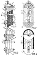
- a rotary arm 2 is fastened in a conventional manner, to which the support rods 3, 3a for the winding template sets 4, 4a are attached. These are connected to their supporting rods in a rotationally locking but axially removable manner and the axial displacement can be blocked by adjusting rings 5.
- the support rods 3, 3a are fastened to the rotary arm 2 via an intermediate body 6, which can be adjusted radially in a longitudinal groove 7 by actuating a fixing screw 8 on the rotary arm 2.
- a clamping screw 9 is provided at the inner end of the support rod 3, 3a, with which the rotatability of the support rod or the template set can be locked and released as required.
- the wire coils 11a, 11b, 11c wound in the stencil chambers 10 are interconnected in a known manner by wire connections with the correct polarity, so that they can be further treated as a unit and introduced into the stator 12.
- the template chambers 10 are wide in shape and the winding process is controlled so that the coil strands are given a flat cross section. This preparatory measure facilitates the subsequent insertion of the coils into the narrow grooves 21 of a stator 12 and the use of the known insertion strips.
- the template set 4 is provided with a support body 13 which forms a piece with the continuous template hub 14 and which extends perpendicularly to the template cutting plane into the template-free space.
- the support surfaces 16a, 16b, 16c of the support body which are provided with raised retaining edges 15 on both sides, are formed mirror-like to the opposite set of templates 4, the winding radii also matching.
- the template hub 14 receiving the support rod 3 is arranged in the present example so that the axis of the support rod 3 runs at a small distance from the geometric shape axis 17 of the half template.
- the winding system is shown in an operating state with the coil set fully wound.
- the rotary arm 2 is first pivoted until the template set 4 is in the upper apex position shown.
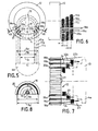
- the rotation lock of the support rod 3 is released by loosening the clamping screw 9, whereupon the support rod with the template set 4 and the support body 13 is rotated by 180 ° and placed in the position according to FIGS. 3 and 4, the intermediate body 6 being the bearing for the support rod 3 works.
- the semicircular coil heads are released, while the vertical coil strands still remain in shape in their stencil chambers 10 and now hang on the support surfaces 16a, 16b, 16c of the support body 13, so that the inherently rigid coil shape is retained.
- the finished coil sets can now be brought into the insertion strips 18a, 19a, 20a (FIG. 6) without the risk of deformation.
- the adjusting rings 5 are loosened so that the template sets 4, 4a can be axially removed from their supporting rods 3, 3a and the entire template-coil complex can then be transported.
- the upper coil heads are securely suspended on the support body 13 by the coil weight, while the vertical coil strands are held in a positive manner in the template chambers 10 of the upper template set 4 and the lower 4a.
- FIGS. 5, 6 and 7 show the arrangement of the insertion strips 18a, 18b, 19a, 19b, 20a, 20b, the stator 12 being rotated in its receiving bearing in such a way that the group of grooves to be fitted in the lower vertex region is symmetrical to the vertical central axis.
- the insertion strips are preparatively inserted into the slots 21 of the stator in such a way that their head parts consisting of the spread tongues 22a, 22b protrude from the stator slots.
- the lengths of the expanded strip head parts are also graduated.
- each pair of cooperating strips is colored by its own color, e.g. B. the strips 18a, 18b marked red, the strips 19a, 19b green and the strips 20a, 20b blue, or colored.
- the spreading angles of the power strips are selected so that the tongues of two adjacent strips can touch each other, so that the inadvertent insertion of a coil strand between two strips is avoided and the attachment of the entire coil set to the strips can be carried out completely specifically and safely in a short time.
- the coil set hanging on the support body 13 is transferred directly into the spaces 23 of the spread head pieces of the insertion strips 18, 19, 20 (a / b), so that the coils are now carried by these head pieces.
- the upper template set 4 is relieved of load with the support body 13 and can be removed from the coil set together with the lower template set 4a.
- the coils 11a, 11b, 11c are then pushed in the direction of the arrow up to the stator or to the extent that they reach the clamping area 24 of the insertion strips.
- the subsequent introduction of the complete coil set in the stator can be done in a known manner, for. B. done in that the connecting bars connected to a pulling device are pulled axially through the stator bore and thereby pull the coil strands into the grooves 21.
- the spreading spaces 23 of the insertion strips shown in FIG. 7 also facilitate the attachment of the deck slides, which can be inserted pushed over the coil strands.
- stator 12 is rotated further by the pole step, in the present example by 90 °, until the group of slots to be occupied is again in the lower apex position according to FIG. 5.
- the dimensions of the slot pitch circle and the division module determine the dimensions of the coil sets to be wound, in particular the chord lengths Sa, Sb, Sc.
- stators are also supplied, in which the stated chord lengths and the profiles of the coil chambers deviate from the standards, so that reworking of the wound coils or the procurement of special winding templates is necessary. Since the deviations are usually only slight, the above-mentioned effort can be avoided by placing the stencils according to FIG. 8 in each case by placing an insert shell 25 or more on the different chord length, e.g. B. Sa 'can be adapted, a template set with the next smaller dimensions is expediently used.
- the insert shell 25 can, for. B. releasably connected by a plug-in cone 26 with the base template.
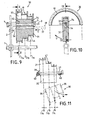
- FIGS. 9 to 11 show a further exemplary embodiment of a template set with a support body, which is particularly advantageous for multi-wire stack windings. Parts corresponding to the first embodiment have the same reference numerals.
- FIGS. 9 and 10 show, in a manner similar to FIGS. 1 and 2, a template set 30 which is pushed onto the support rod 3 and which is fastened to the rotating arm 2 of the winding machine by the tensioning screw 9.
- the template set is axially secured by an adjusting ring 5.
- the winding process is completed and the wire coils 11a, 11b and 11c lie flat in the template chambers 10.
- the coil set is placed in its upper apex position, the downward hanging coil strands being guided through the wire chambers of the lower template set, not shown.
- the support body 31 is an independent body separate from the template set 30 and is provided with a sensor 32 which projects into the hollow interior 33 of the templates, where it is held non-positively but releasably. This is e.g. B. achieved by two attached in the template elastic guide strips 34, between which the transducer 32 can be inserted, wherein a holding voltage is generated which is sufficient to support the support body 31.
- the transducer 32 has the longitudinal bore, which, when the transducer is inserted, coincides with the bores 35 in the outer walls of the template set, so that the support rod 3 inserted into the bores establishes the connection between the template set 30 and the transducer 32 with the rotary arm 2.
- the support body 31 is provided with a second profiled receiving bore 36, which serves for the rotationally locking reception of a second support rod 37, which on the one hand can be provided with a holding button 38 and on its insertion-side end has a driver bolt 39 which is automatically placed in a transverse position is and the removal of the template set from the support rod 3 facilitated, which remains on the rotary arm 2.
- the second support rod 37 was inserted into the second receiving bore 36 (arrow E), so that this rod now carries the template set with the coils and the support body.
- the support rod 37 can be placed on two support rails 40 (FIG. 11) to facilitate further handling.
- the support body 31 with its pick-up 32 and the template set 30 is pivoted about the axis of the support rod 37 by 180 ° (arrow D), so that the template set 30 now occupies the lower and the support body 31 the upper apex position, the wire spools 11a, 11b, 11c automatically lifted out of the template chambers 10 of the templates and from the wire chambers 41 of the support body 31 are adopted.
- the template set 30 can now be detached from the pick-up 32 and removed from the area of the coil strands (arrow W, FIG. 11).
Landscapes
- Engineering & Computer Science (AREA)
- Manufacturing & Machinery (AREA)
- Power Engineering (AREA)
- Manufacture Of Motors, Generators (AREA)
Applications Claiming Priority (2)
| Application Number | Priority Date | Filing Date | Title |
|---|---|---|---|
| DE3439769A DE3439769A1 (de) | 1984-10-31 | 1984-10-31 | Anlage und arbeitsverfahren zum einbringen der spulen in den stator elektrischer maschinen |
| DE3439769 | 1984-10-31 |
Publications (3)
| Publication Number | Publication Date |
|---|---|
| EP0180167A2 EP0180167A2 (de) | 1986-05-07 |
| EP0180167A3 EP0180167A3 (en) | 1987-03-25 |
| EP0180167B1 true EP0180167B1 (de) | 1990-05-09 |
Family
ID=6249154
Family Applications (1)
| Application Number | Title | Priority Date | Filing Date |
|---|---|---|---|
| EP85113648A Expired - Lifetime EP0180167B1 (de) | 1984-10-31 | 1985-10-26 | Vorrichtung und Verfahren zum Einbringen der Spulen in den Stator elektrischer Maschinen |
Country Status (3)
| Country | Link |
|---|---|
| US (1) | US4683650A (enExample) |
| EP (1) | EP0180167B1 (enExample) |
| DE (2) | DE3439769A1 (enExample) |
Families Citing this family (5)
| Publication number | Priority date | Publication date | Assignee | Title |
|---|---|---|---|---|
| DE3812728A1 (de) * | 1988-04-16 | 1989-10-26 | Veser F | Wickelschablone fuer in den stator einer elektrischen maschine einziehbare spulen |
| US5825652A (en) * | 1995-09-08 | 1998-10-20 | Gerber Garment Technology, Inc. | Sample garment making system |
| US6349463B1 (en) * | 1999-09-30 | 2002-02-26 | Reliance Electric Technologies, Llc | Method of making an electric motor stator assembly |
| CN103326524B (zh) * | 2013-06-09 | 2015-04-22 | 镇江中船现代发电设备有限公司 | 内外层塔形线圈绕线模具及线圈绕制方法 |
| CN117013774B (zh) * | 2023-10-07 | 2023-12-15 | 苏州南新电机有限公司 | 一种电机定子生产的嵌线设备 |
Family Cites Families (8)
| Publication number | Priority date | Publication date | Assignee | Title |
|---|---|---|---|---|
| DE7307567U (de) * | 1973-08-09 | Balzer & Droell Kg | Vorrichtung zum Abstreifen von Drahtspulen für elektrische Maschinen von prismatischen Wickelschablonen | |
| AT249170B (de) * | 1964-08-25 | 1966-09-12 | Vogel Pumpen | Vorrichtung zum Bewickeln der Ständer von zwei- oder mehrpoligen Ein- oder Mehrphasenmaschinen |
| AT277379B (de) * | 1967-10-09 | 1969-12-29 | Elin Union Ag | Schablone zum Wickeln und Einbringen von Spulen in Statoren elektrischer Maschinen im Spuleneinziehverfahren |
| DE2443380A1 (de) * | 1974-09-11 | 1976-04-01 | Veser F | Verfahren und vorrichtung zum einziehen vorgewickelter spulen |
| DE2808050A1 (de) * | 1978-02-24 | 1979-08-30 | Balzer & Droell Kg | Verfahren und vorrichtung zum wickeln mehrerer in ein statorblechpaket einzuziehender spulen |
| US4217938A (en) * | 1979-03-12 | 1980-08-19 | General Electric Company | Apparatus and method for making dynamoelectric machine windings |
| DE3209621A1 (de) * | 1982-03-17 | 1983-09-29 | Franz 7980 Ravensburg Veser | Verfahren und einrichtungen zum herstellen, zurichten und einbringen von spulensaetzen fuer statoren elektrischer maschinen |
| DE3222181A1 (de) * | 1982-06-12 | 1983-12-15 | Otto 7982 Baienfurt Rist | Vorrichtung zur herstellung von rotor- oder statorspulen fuer elektrische maschinen |
-
1984
- 1984-10-31 DE DE3439769A patent/DE3439769A1/de active Granted
-
1985
- 1985-10-26 DE DE8585113648T patent/DE3577627D1/de not_active Expired - Fee Related
- 1985-10-26 EP EP85113648A patent/EP0180167B1/de not_active Expired - Lifetime
- 1985-10-29 US US06/792,557 patent/US4683650A/en not_active Expired - Fee Related
Also Published As
| Publication number | Publication date |
|---|---|
| DE3439769C2 (enExample) | 1988-11-24 |
| DE3439769A1 (de) | 1986-04-30 |
| DE3577627D1 (de) | 1990-06-13 |
| US4683650A (en) | 1987-08-04 |
| EP0180167A2 (de) | 1986-05-07 |
| EP0180167A3 (en) | 1987-03-25 |
Similar Documents
| Publication | Publication Date | Title |
|---|---|---|
| EP1771932B1 (de) | Stator einer elektrischen maschine mit einer wellenwicklung | |
| DE3114407C2 (enExample) | ||
| DE2630183C3 (de) | Vorrichtung zum Einziehen von Wicklungen in Nuten von Statoren von Elektromotoren | |
| DE840284C (de) | Magnetspule und Verfahren zu ihrer Herstellung | |
| DE2001677A1 (de) | Wicklungsvorrichtung fuer die Staendernuten elektrischer Maschinen | |
| DD141738A5 (de) | Vorrichtung zum wickeln von spulen fuer statoren elektrischer maschinen | |
| DE1966673C3 (de) | Vorrichtung zur Herstellung eines Bewehrungskäfigs für Spannbetonrohre | |
| EP0180167B1 (de) | Vorrichtung und Verfahren zum Einbringen der Spulen in den Stator elektrischer Maschinen | |
| DE3702265C2 (de) | Verfahren und Vorrichtung zum Austausch von Spulen und Hülsen an Vorspinnmaschinen | |
| DE4244488C1 (de) | Verfahren und Vorrichtung zur Herstellung einer Wellenwicklung, insbesondere für Drehstromgeneratoren | |
| EP2388887A2 (de) | Polkette | |
| DE4300764C2 (de) | Verfahren und Vorrichtung zur Herstellung einer Wellenwicklung | |
| DE1685830A1 (de) | Maschine zum Herstellen von Kabeln oder Seilen | |
| DE69311473T2 (de) | Verfahren und Vorrichtung zum Bewickeln von Ringkernspulen | |
| DE3009022A1 (de) | Verfahren und geraet zum herstellen einer dynamomaschinenwicklung | |
| DE3209621A1 (de) | Verfahren und einrichtungen zum herstellen, zurichten und einbringen von spulensaetzen fuer statoren elektrischer maschinen | |
| DE102004059087A1 (de) | Wickelvorrichtung für eine Feldspule, Fertigungsvorrichtung und elektrische Maschine | |
| EP0761009B1 (de) | Verfahren und vorrichtung zum bewickeln eines geschlossenen ringkerns für transformatoren und drosseln hoher leistungen | |
| DE2018813C3 (de) | Verfahren zum Herstellen von Anschlüssen an elektrischen Spulen und Vorrichtung zur Durchführung des Verfahrens | |
| DE2953092C2 (de) | Verfahren und Einrichtung bei Wickelautomaten | |
| DE4403919C2 (de) | Verfahren und Vorrichtung zum Wickeln von Spulen für elektrische Motoren oder Generatoren | |
| DE19748242B4 (de) | Verfahren zum Herstellen von Drahtspulen auf in konvexen Ebenen angeordneten Wickelkörpern | |
| EP0963031A2 (de) | Verfahren und Einziehwerkzeugteil zum Herstellen eines Stators für elektrische Maschinen | |
| DE2434480C3 (de) | Spulenwickelvorrichtung zum Herstellen der Spulen für Wicklungen elektrischer Maschinen | |
| EP0574841A1 (de) | Verfahren und Vorrichtung zum Herstellen von Stator- oder Rotorwicklungen elektrischer Maschinen aus Paralleldrähten |
Legal Events
| Date | Code | Title | Description |
|---|---|---|---|
| PUAI | Public reference made under article 153(3) epc to a published international application that has entered the european phase |
Free format text: ORIGINAL CODE: 0009012 |
|
| AK | Designated contracting states |
Kind code of ref document: A2 Designated state(s): DE FR GB IT |
|
| PUAL | Search report despatched |
Free format text: ORIGINAL CODE: 0009013 |
|
| AK | Designated contracting states |
Kind code of ref document: A3 Designated state(s): DE FR GB IT |
|
| 17P | Request for examination filed |
Effective date: 19870818 |
|
| 17Q | First examination report despatched |
Effective date: 19891004 |
|
| GRAA | (expected) grant |
Free format text: ORIGINAL CODE: 0009210 |
|
| AK | Designated contracting states |
Kind code of ref document: B1 Designated state(s): DE FR GB IT |
|
| REF | Corresponds to: |
Ref document number: 3577627 Country of ref document: DE Date of ref document: 19900613 |
|
| GBT | Gb: translation of ep patent filed (gb section 77(6)(a)/1977) | ||
| ET | Fr: translation filed | ||
| ITF | It: translation for a ep patent filed | ||
| PLBE | No opposition filed within time limit |
Free format text: ORIGINAL CODE: 0009261 |
|
| STAA | Information on the status of an ep patent application or granted ep patent |
Free format text: STATUS: NO OPPOSITION FILED WITHIN TIME LIMIT |
|
| 26N | No opposition filed | ||
| ITTA | It: last paid annual fee | ||
| PGFP | Annual fee paid to national office [announced via postgrant information from national office to epo] |
Ref country code: GB Payment date: 19931210 Year of fee payment: 9 Ref country code: FR Payment date: 19931210 Year of fee payment: 9 |
|
| PGFP | Annual fee paid to national office [announced via postgrant information from national office to epo] |
Ref country code: DE Payment date: 19931216 Year of fee payment: 9 |
|
| PG25 | Lapsed in a contracting state [announced via postgrant information from national office to epo] |
Ref country code: GB Effective date: 19941026 |
|
| GBPC | Gb: european patent ceased through non-payment of renewal fee |
Effective date: 19941026 |
|
| PG25 | Lapsed in a contracting state [announced via postgrant information from national office to epo] |
Ref country code: FR Effective date: 19950630 |
|
| PG25 | Lapsed in a contracting state [announced via postgrant information from national office to epo] |
Ref country code: DE Effective date: 19950701 |
|
| REG | Reference to a national code |
Ref country code: FR Ref legal event code: ST |