EP0178490A2 - Dispositif de détection de contaminants pouvant être filtrés dans des gaz - Google Patents
Dispositif de détection de contaminants pouvant être filtrés dans des gaz Download PDFInfo
- Publication number
- EP0178490A2 EP0178490A2 EP85111982A EP85111982A EP0178490A2 EP 0178490 A2 EP0178490 A2 EP 0178490A2 EP 85111982 A EP85111982 A EP 85111982A EP 85111982 A EP85111982 A EP 85111982A EP 0178490 A2 EP0178490 A2 EP 0178490A2
- Authority
- EP
- European Patent Office
- Prior art keywords
- turntable
- filter
- suction head
- contamination
- suction
- Prior art date
- Legal status (The legal status is an assumption and is not a legal conclusion. Google has not performed a legal analysis and makes no representation as to the accuracy of the status listed.)
- Granted
Links
Images


Classifications
-
- G—PHYSICS
- G01—MEASURING; TESTING
- G01N—INVESTIGATING OR ANALYSING MATERIALS BY DETERMINING THEIR CHEMICAL OR PHYSICAL PROPERTIES
- G01N1/00—Sampling; Preparing specimens for investigation
- G01N1/02—Devices for withdrawing samples
- G01N1/22—Devices for withdrawing samples in the gaseous state
- G01N1/2202—Devices for withdrawing samples in the gaseous state involving separation of sample components during sampling
- G01N1/2214—Devices for withdrawing samples in the gaseous state involving separation of sample components during sampling by sorption
-
- G—PHYSICS
- G01—MEASURING; TESTING
- G01T—MEASUREMENT OF NUCLEAR OR X-RADIATION
- G01T7/00—Details of radiation-measuring instruments
- G01T7/02—Collecting means for receiving or storing samples to be investigated and possibly directly transporting the samples to the measuring arrangement; particularly for investigating radioactive fluids
- G01T7/04—Collecting means for receiving or storing samples to be investigated and possibly directly transporting the samples to the measuring arrangement; particularly for investigating radioactive fluids by filtration
-
- G—PHYSICS
- G01—MEASURING; TESTING
- G01N—INVESTIGATING OR ANALYSING MATERIALS BY DETERMINING THEIR CHEMICAL OR PHYSICAL PROPERTIES
- G01N1/00—Sampling; Preparing specimens for investigation
- G01N1/02—Devices for withdrawing samples
- G01N1/22—Devices for withdrawing samples in the gaseous state
- G01N1/24—Suction devices
-
- G—PHYSICS
- G01—MEASURING; TESTING
- G01N—INVESTIGATING OR ANALYSING MATERIALS BY DETERMINING THEIR CHEMICAL OR PHYSICAL PROPERTIES
- G01N1/00—Sampling; Preparing specimens for investigation
- G01N1/02—Devices for withdrawing samples
- G01N1/22—Devices for withdrawing samples in the gaseous state
- G01N1/2202—Devices for withdrawing samples in the gaseous state involving separation of sample components during sampling
- G01N2001/222—Other features
- G01N2001/2223—Other features aerosol sampling devices
Definitions
- the invention relates to a device for detecting gas contaminations which can be filtered out, with an annular filter web moved by means of a horizontal compact rotary plate above a suction head with a pump connection.
- the aim of the invention is therefore a device for detecting gas contaminations which can be filtered out, which works as simply and reliably as possible, offers variation possibilities and in particular is also adapted to longer, uninterrupted measurement tasks which can be managed without maintenance.
- the device of the type mentioned at the outset which was developed for this purpose, is characterized in that the compact turntable supports the entire filter collecting the contamination and is provided along the circular path with holes or bores which cooperate with the lip shape of the suction head, which by means of a gimbal spring bearing is pressed from below against the plane-parallel turntable.
- the turntable can be rotated continuously by motor operation or, in particular, be moved step by step with a stepper motor.
- a gradual feed e.g. by means of a lifting magnet which actuates a sliding element which engages in a toothed ring which is fixedly connected to the rotary actuator and moves it further by a certain angle.
- the step feed can also be controlled using perforated plates and light barriers.
- the holes or bores provided on the turntable, which interact with the suction head are preferably formed by a ring of closely adjacent, generally oval radial slots which are tapered downwards.
- the suction head then has a preferably slightly larger radial slot corresponding to the lower slot cross section within a relatively wide “suction lip”.
- materials such as Plexiglas R (polymethacrylate) or polytetrafluoroethylene are suitable.
- the sliding surfaces must be machined flat and smooth.
- the collection capacity of such a filter is rela- t i v in size and allows a continuous operation upper long periods of time, in particular two pivot filters are provided side by side in a device which can operate alternately.
- Such a collecting and measuring device is therefore preferably to be equipped with a plurality of detectors which are arranged at an angle to one another above the rotary filter because of their space requirement.
- the collection facility include e.g. a first detector with which the pollutant is to be measured already during sampling and a second detector with which the pollutant is to be measured immediately after sampling, this detector cannot be reached immediately after sampling when the rotary filter is advanced by a (smeared) collection point.
- a program feed via a corresponding number of collection points is therefore preferably provided, which then brings a collected sample directly under this detector
- n is provided in the turntable, which is equal to z. ⁇ n + 1 or z. ⁇ n - 1, where ⁇ n is the distance between the collection point and the detector (measured in number of slides) and z is the number of samples per plate cycle. It is also required that n + 1 or n - 1 is not a prime number
- the rotary filter is used to the maximum with a fixed feed program, since the location of the sampling per plate revolution progresses or is set back by one sampling location.
- the usual radiation measuring probes such as Geiger-Müller counters, proportional counters, scintillation detectors or semiconductor detectors, are suitable as detectors for determining radioactive air contaminants that can be filtered out.
- a plurality of detectors can be provided with an angular offset above the filter at a distance which corresponds to the turntable advance between two sampling (or an integer multiple thereof).
- Such additional detectors can provide information about the longevity or short life of the radioactive substances collected and / or the energy of the emitted radiation.
- Non-radioactive bulk samples can, for example, use their fluorescence behavior or the like. been analyzed.
- the air filter or measuring filter provided on the turntable can be a glass fiber paper or membrane filter suitable for collecting aerosol particles.
- filter discs with selective collection capacity can be provided.
- the turntable itself or an attachment can be provided with cup-like bores or filter chambers, which have a filter bottom or are designed as blind bores, the bottom of which is perforated and expediently covered with filter paper.
- the turntables are preferably accommodated in an airtight housing which has an inlet opening and, connected to this, a pipe or hose line and, in particular, a guide hood above the suction head.
- a housing has a separate chamber for each rotary filter, in which the rotary filter can be removed on rails.
- a common pump system can be provided, from which the two suction heads branch off via a two-way valve.
- the housing 1 comprises two chambers 2 and 3, in each of which a rigid, flat, approximately 10 mm thick turntable 4 made of Plexiglas® or Teflon of 20 cm in diameter with a ring of radial slots 5 is arranged which an aerosol filter 6 rests on.
- a suction head 7 made of polytetrafluoroethylene with suction lips 8, which is connected via line 9 to a suction system, not shown.
- the gas or air to be filtered is drawn in via a housing opening 10 which is connected via a line 11 to a “hood” 12 above the sampling point.
- two detectors are designated, which are not further developed here.
- the turntable 4 is fixedly connected to a ring gear 15, which is actuated by a signal-controlled lifting magnet 16 which, as a sliding element, has a tooth or driver 17 which engages in the ring gear accordingly.
- the turntable arrangement is mounted on a base plate 2 'or 3' mounted on rails and can thus be pulled out of the chamber 2 or 3 provided with an acceptable front plate to replace the filter together with the auxiliary devices mounted on the base plate.
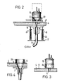
- Figure 2 shows the "compensation bearing" of the suction head 7, which has on its underside two pans 18, in which the tips of pins 19 are mounted, which are slidable in guide sleeves 20 and are pressed into the pans by coil springs 21, the lower ends of which wrapped around the sleeves 20 and mounted on the base plate 2 'and the upper ends of which are attached to the pins 19.
- FIG. 2 also shows the conical shape of the radial slits 5 to be tapered downward and a detector arranged directly above the collecting point, which is connected through an end window counter tube or the like. can be formed.
- an aperture-shaped air duct 22 with a bore 23 which can be connected to a hose 11 and via which the air (or gas) to be monitored can be sucked in below the debector to the filter .
- FIG. 3 shows the arrangement of a detector 13 over a sample previously collected on the filter 6.
- an aperture 24 is located between the filter and the detector, by means of which an influence on the activity determination of the aggregate sample by neighboring samples is reduced.
- Figures 1-3 show the arrangement according to the invention with dust or aerosol filter.
- sorption material can also be provided over the suction head.
- ring attachments 25 as outlined in FIG. 4, which are placed over the receptacle 5 of the turntable 4, which in this case is designed as a circular bore, after placing a filter paper or a filler mat 6 on it. These rings 25 then form wells with the filter 6 as the bottom, into which adsorber material can be filled.
- FIG. 5 The arrangement indicated in FIG. 5 is more expedient than this very simple embodiment, in which a rotary filter attachment 26 with bores 27, which face the bores 5 of the rotary plate, is arranged above the filter-coated rotary plate.
- the turntable 4 itself can be provided with blind bores 28 which are closed off by a perforated plate 29 and thus form cup-like recesses into which the sorption material 27 'can be filled.
- a shoulder with an inserted or glued-in filter disk 29 can also be provided.
- FIG. 7 An arrangement analogous to FIG. 5 is indicated in FIG. 7, in which the cup-like recesses of the rotary filter attachment 26 formed with the use of the filter 6 are adapted to the radial slot shape.
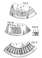
- FIG. 8 schematically shows a top layer on a turntable 4 with nep rings 2 5 placed on cylindrical bores 5 5 above a suction head 7 with a lip 8 indicated by dashed lines.
- a turntable with a radial slot ring is indicated above a suction head 7 with a relatively wide lip, the suction opening 29 of which is adapted to the lower tapered cross section 5 '(mostly omitted in the drawings) of the radial slot on the underside of the turntable
- the turntable 4 has a relatively wide ring of small cylindrical bores or holes in the vicinity of the circumference, which, as indicated in FIG. 12, may, but need not, be tapered downwards.
- a suction head 7 interacts with a suction slot 30. This concept is essentially intended for slow, continuous movement of the turntable.
- the arrangement according to FIG. 11 would also be suitable for a continuous movement of the turntable, in which the suction opening of the suction head 7 covers three (or more) radial slots and the suction lip is wider than the lower tapered cross-section of the radial slot bores of the rotary member 4. These too
- the arrangement is suitable for quasi-continuous air filtering.
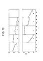
- the arrangement was equipped with end window counter tubes arranged correspondingly offset from one another, namely with a first counter tube in position 1, which already determines the aerosol activity during the sample recording, with a second counter tube (immediately after sampling) in position 8, which after completion of the Sampling and moving the turntable by seven sampling positions (for a new sampling) begins with the measurement and with a third counter tube at position 43, with which the activity is measured after a further five days.
- the radio iodine content in the ambient atmosphere was monitored with silver-zedith sorbent in the manner indicated in FIG. 6.
- an arrangement with 3 detectors is particularly suitable, in which the 1st detector is arranged directly above the suction point and is used for ongoing monitoring. This detector provides the necessary immediate information, especially in the event of an accident.
- ThB ThB
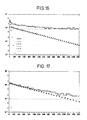
- the experimental results obtained are shown in FIGS. 13 to 17.
- the evaluation of the sample for example, with 0.1 Bq results in a detectable activity concentration of approx. 0.001 Bo / m 3 at an air throughput of 1 m 3 / h, a total count yield of 0.2 and a collection and measuring time of 48 h Value that corresponds to the required detection limit, a result that even a specialist would not have expected. It should be noted that the rotary filter measuring system built for tests was not yet optimally designed.
- the second detector is reached by the step feed after the end of the collection period and provides data on the subsequent decay behavior, while the long-term total beta activity concentration present at the measuring location is determined with the third detector.
- the air flow rate is expediently 1 m 3 / h and 1 to 2 days are selected as the cycle time for the step feed.
- the detectors mentioned above can e.g. be provided in places 1, 3 and 11.
- RaB and ThB must be taken into account in beta activity measurements, the ratio of which is subject to weather influences an overlay by artificial radioactivity can be determined relatively sensitive.
- the computer-cooled decay analysis can also be used to determine short-lived, aerosol-bound radionuclides of non-natural origin, the half-lives of which differ sufficiently from those of the ThB if sufficient activity is present.
- Figure 18 shows the curves for the dependency of the decay course of the radioactivity of radioactive samples, consisting of the natural radionuclides with 100 parts for RaB and 10 parts for ThB, additionally superimposed by short-lived (artificial) radionuclides with 100 parts with half-lives 1h, 2h, 4h , 8h, 20h, 40h and 80h.
Landscapes
- Life Sciences & Earth Sciences (AREA)
- Health & Medical Sciences (AREA)
- Analytical Chemistry (AREA)
- General Physics & Mathematics (AREA)
- Molecular Biology (AREA)
- Physics & Mathematics (AREA)
- Chemical & Material Sciences (AREA)
- Biochemistry (AREA)
- Biomedical Technology (AREA)
- General Health & Medical Sciences (AREA)
- Engineering & Computer Science (AREA)
- Immunology (AREA)
- Pathology (AREA)
- High Energy & Nuclear Physics (AREA)
- Spectroscopy & Molecular Physics (AREA)
- Sampling And Sample Adjustment (AREA)
- Measurement Of Radiation (AREA)
Applications Claiming Priority (2)
| Application Number | Priority Date | Filing Date | Title |
|---|---|---|---|
| DE3436800 | 1984-10-06 | ||
| DE19843436800 DE3436800A1 (de) | 1984-10-06 | 1984-10-06 | Vorrichtung zur erfassung von ausfilterbaren gaskontaminationen |
Publications (3)
| Publication Number | Publication Date |
|---|---|
| EP0178490A2 true EP0178490A2 (fr) | 1986-04-23 |
| EP0178490A3 EP0178490A3 (en) | 1988-01-27 |
| EP0178490B1 EP0178490B1 (fr) | 1991-11-21 |
Family
ID=6247335
Family Applications (1)
| Application Number | Title | Priority Date | Filing Date |
|---|---|---|---|
| EP85111982A Expired - Lifetime EP0178490B1 (fr) | 1984-10-06 | 1985-09-21 | Dispositif de détection de contaminants pouvant être filtrés dans des gaz |
Country Status (4)
| Country | Link |
|---|---|
| US (1) | US4795612A (fr) |
| EP (1) | EP0178490B1 (fr) |
| JP (1) | JPS6191539A (fr) |
| DE (2) | DE3436800A1 (fr) |
Families Citing this family (23)
| Publication number | Priority date | Publication date | Assignee | Title |
|---|---|---|---|---|
| IT1239900B (it) * | 1990-03-30 | 1993-11-23 | Getters Spa | Metodo per determinare la fine della vita utile di un purificatore di gas e relativa apparecchiatura |
| JP2547354B2 (ja) * | 1990-06-18 | 1996-10-23 | 迪郎 芝崎 | 粘稠性を有する検体の捕捉方法と検体捕捉装置 |
| BG49948A3 (en) * | 1991-01-04 | 1992-03-16 | Добромир Пресиянов | Device for measuring of mean volume activities and secret energy of radon and torone filial products in free air |
| USRE36341E (en) * | 1993-10-14 | 1999-10-12 | Dade Behring Inc. | Automatic sample container handling centrifuge and a rotor for use therein |
| KR960704634A (ko) * | 1993-10-14 | 1996-10-09 | 미리암 디. 메코너헤이 | 샘플 용기 자동 처리식 원심 분리기 및 원심 분리기용 회전자(Automatic Sample Container Handling Centrifuge and a Rotor for Use Therein) |
| DE4434222C1 (de) * | 1994-09-26 | 1996-02-08 | Ilka Praezimatik Kryotechnik G | Probennahme- und Meßeinrichtung zur Untersuchung von in Gasen enthaltenen Stoffen |
| US5955373A (en) * | 1997-11-05 | 1999-09-21 | Zymark Corporation | Environmentally controlled system for processing chemical products |
| FR2775348B1 (fr) * | 1998-02-20 | 2000-04-07 | Cogema | Appareil et procede de detection d'aerosols radioactifs |
| CA2277447C (fr) * | 1998-07-09 | 2008-01-22 | Sapporo Breweries Ltd. | Appareil de preparation d'echantillons et appareil de pulverisation pour la preparation d'echantillons |
| WO2002049761A2 (fr) * | 2000-12-18 | 2002-06-27 | Protedyne Corporation | Systeme et procede de laboratoire automatise |
| CA2369802C (fr) * | 2002-01-29 | 2007-12-18 | Centre De Recherche Industrielle Du Quebec | Appareil et methode de determination quantitative de particules |
| US6867413B2 (en) | 2002-06-21 | 2005-03-15 | Rupprecht & Patashnick Company, Inc. | High-flow rate, low-noise, gas sampling apparatus and methods for collecting and detecting particulate in a gas |
| US6769316B2 (en) * | 2002-06-21 | 2004-08-03 | Rupprecht & Patashnick Company, Inc. | Sampling cartridge for gas sampling apparatus |
| US6854344B2 (en) * | 2002-12-19 | 2005-02-15 | The Johns Hopkins University | Sample retrieval device for aerosol collection |
| US20060014300A1 (en) * | 2004-07-15 | 2006-01-19 | Maurer Scott M | Sensor for detection and identification of biological particles |
| GB0421352D0 (en) * | 2004-09-24 | 2004-10-27 | City Tech | Sampling and analysis system and method |
| WO2007109096A2 (fr) * | 2006-03-16 | 2007-09-27 | Thiesen Jack H | Procede et appareil destines a des processus chimiques mettant en oeuvre des empreintes moleculaires |
| US20090320620A1 (en) * | 2008-06-27 | 2009-12-31 | Nuctech Company Limited | Door-type passenger security inspection apparatus and method for detecting contraband articles such as narcotic drugs, explosives |
| US20110027905A1 (en) * | 2009-08-03 | 2011-02-03 | Henderson Douglas B | Systems and Methods for Collection and Analysis of Analytes |
| ITUA20162670A1 (it) * | 2016-04-18 | 2017-10-18 | Envint S R L | Apparato per il campionamento di inquinanti atmosferici in fase gassosa e particellare. |
| US11268886B2 (en) * | 2019-06-27 | 2022-03-08 | The Procter & Gamble Company | Portable automatic air sampling device and method of collecting air samples therefrom |
| CN114274718B (zh) * | 2021-12-29 | 2024-04-05 | 内蒙古华测电力科技有限公司 | 一种气体浓度检测装置以及检测方法 |
| CN116482297A (zh) * | 2022-01-17 | 2023-07-25 | 霍尼韦尔国际公司 | 带有集成流动调节部件的气体检测装置 |
Family Cites Families (22)
| Publication number | Priority date | Publication date | Assignee | Title |
|---|---|---|---|---|
| US1944267A (en) * | 1931-02-09 | 1934-01-23 | American Smelting Refining | Filtering |
| DE1108818B (de) * | 1959-04-15 | 1961-06-15 | Commissariat Energie Atomique | Tragbares Registriergeraet mit bewegbarem Filter zum Messen der Strahlungsintensitaet radioaktiver Aerosole |
| DE1147326B (de) * | 1961-10-24 | 1963-04-18 | Landis & Gyr Ag | Filterband-Transporteinrichtung fuer Anlagen zum Messen der Radioaktivitaet von Aerosolen |
| FR1321571A (fr) * | 1962-02-08 | 1963-03-22 | Commissariat Energie Atomique | Mesureur de concentration des particules radioactives en suspension dans un gaz |
| DE1214024B (de) * | 1964-08-06 | 1966-04-07 | Fraunhofer Ges Forschung | Automatischer Staubprobensammler des Membranfiltertyps |
| FR1484728A (fr) * | 1966-04-18 | 1967-06-16 | Lemer & Cie | Ensembles automatiques pour mesures simultanées sur des échantillons radioactifs, préalablement disposés sur un stockeur unique |
| FR1526275A (fr) * | 1967-04-13 | 1968-05-24 | Commissariat Energie Atomique | Procédé et appareil d'enregistrement simultané de la concentration dans l'atmosphère des descendants solides à vie courte du radon |
| US3540261A (en) * | 1968-05-10 | 1970-11-17 | Center For The Environment & M | Atmosphere sampling device |
| FR2184535B1 (fr) * | 1972-05-19 | 1980-03-21 | Commissariat Energie Atomique | |
| US3926593A (en) * | 1974-09-19 | 1975-12-16 | Arthur M Squires | Precoating panel bed for filtering aerosol of micron-size particulates |
| US4056818A (en) * | 1975-12-29 | 1977-11-01 | Robert Oddsen | Automatic surveillance system for time sequence operations |
| US4088737A (en) * | 1976-11-02 | 1978-05-09 | The United States Of America As Represented By The United States Department Of Energy | Dry method for recycling iodine-loaded silver zeolite |
| US4236070A (en) * | 1978-02-06 | 1980-11-25 | Lee Herbert S | Shaft position encoder |
| DK141542B (da) * | 1978-07-12 | 1980-04-14 | Medi Lab Medicinsk Lab As | Fremgangsmåde og apparat til måling af intensiteten fortrinsvis af gamma-stråling af i en væskeprøve indeholdt strålingsaktivt bundfald. |
| US4290786A (en) * | 1978-12-04 | 1981-09-22 | Ecotech Corporation | Apparatus for removing particulate matter from a gas stream |
| JPS6010588B2 (ja) * | 1979-08-01 | 1985-03-18 | 東京電力株式会社 | 放射能モニタリング方法 |
| US4260892A (en) * | 1979-08-22 | 1981-04-07 | Bell Telephone Laboratories, Incorporated | Geiger-Mueller radiation detector with means for detecting and indicating the existence of radiation overload |
| US4250531A (en) * | 1979-08-30 | 1981-02-10 | Ahrens Walter C | Switch-arc preventing circuit |
| US4266953A (en) * | 1980-06-02 | 1981-05-12 | The United States Of America As Represented By The Secretary Of The Army | Mechanism for removing dust particles from an engine air cleaner |
| JPS57110974A (en) * | 1980-12-27 | 1982-07-10 | Nippon Atom Ind Group Co Ltd | Automatic radiation measuring apparatus |
| US4462399A (en) * | 1981-10-02 | 1984-07-31 | Minnesota Mining And Manufacturing Company | Powered air respirator and cartridge |
| US4510929A (en) * | 1982-04-30 | 1985-04-16 | Bordoni Maurice E | Disposable radioactive aerosol inhalation apparatus |
-
1984
- 1984-10-06 DE DE19843436800 patent/DE3436800A1/de not_active Withdrawn
-
1985
- 1985-09-21 DE DE8585111982T patent/DE3584713D1/de not_active Expired - Lifetime
- 1985-09-21 EP EP85111982A patent/EP0178490B1/fr not_active Expired - Lifetime
- 1985-09-30 JP JP60215240A patent/JPS6191539A/ja active Pending
-
1987
- 1987-07-17 US US07/075,209 patent/US4795612A/en not_active Expired - Fee Related
Also Published As
| Publication number | Publication date |
|---|---|
| JPS6191539A (ja) | 1986-05-09 |
| DE3584713D1 (de) | 1992-01-02 |
| US4795612A (en) | 1989-01-03 |
| DE3436800A1 (de) | 1986-04-10 |
| EP0178490B1 (fr) | 1991-11-21 |
| EP0178490A3 (en) | 1988-01-27 |
Similar Documents
| Publication | Publication Date | Title |
|---|---|---|
| EP0178490B1 (fr) | Dispositif de détection de contaminants pouvant être filtrés dans des gaz | |
| DE102004018260B4 (de) | Sammelfilter und Verfahren zur quantitativen Analyse von in der Luft suspendierten Schwebteilchen | |
| EP0364687B1 (fr) | Dispositif de prise d'échantillons pour véhicule de surveillance | |
| DE19819513A1 (de) | Feuchtemesser, elektronische Wägemaschine für Feuchtemesser, Filter für Feuchtemesser und Feuchteadsorptionseinheit für Feuchtemesser | |
| DE2660445C2 (de) | Vorrichtung zur quantitativen Analyse der Antigenkonzentration einer Probenlösung unter Verwendung eines Immunoadsorbens | |
| DE4200187C2 (de) | Einrichtung zum Messen zeitlich integrierter spezifischer Aktivitäten von Tochterprodukten von Radon und Thoron in der Luft | |
| DE1539784B1 (de) | Verfahren und Vorrichtung zur kontinuierlichen Messung der Radioaktivitaet von Aerosolen | |
| EP0391256B1 (fr) | Dispositif et procédé pour la détermination de la distribution de tailles de particules et la concentration globale de particules dans un gaz, en particulier dans l'air | |
| DE4440692A1 (de) | Probennahmeeinrichtung zur Untersuchung von in Gasen enthaltenen Stoffen und Verfahren zur Probennahme und Messung | |
| DE4434222C1 (de) | Probennahme- und Meßeinrichtung zur Untersuchung von in Gasen enthaltenen Stoffen | |
| DE3542780C1 (de) | Pruefroehrchen | |
| DE4114400A1 (de) | Verfahren und anordnung zur probeentnahme und messung von radioaktiven gasfoermigen iodverbindungen | |
| EP4425147B1 (fr) | Procédé et appareil de mesure de la concentration de particules absorbant la lumière | |
| DE2251189C2 (de) | Verfahren zum selektiven Messen des in elementarer oder chemisch gebundener Form vorliegenden Jodnuklides ↑1↑↑3↑↑1↑ J | |
| DE4439433A1 (de) | Verfahren und Vorrichtung zur quantitativen Analyse von Luftinhaltsstoffen | |
| DE2802986C2 (de) | Vorrichtung zur Durchführung einer radiochromatographischen Analyse | |
| DE202011001747U1 (de) | Einrichtung zur qualitativen und/oder quantitativen Erfassung von Quecksilberemmissionen | |
| DE3307439C2 (fr) | ||
| DE102023104117A1 (de) | Verfahren und Vorrichtung zur Messung der Konzentration von Licht absorbierenden Partikeln | |
| DE1673263A1 (de) | Einrichtung zur Roentgenoradiometrischen Bestimmung von Elementen in Proben | |
| DE10050863A1 (de) | Verfahren und Vorrichtung zur Entnahme von Luftproben | |
| DE2726304C2 (de) | Vorrichtung zur Bestimmung der Größenverteilung von in Fluiden suspendierten Teilchen | |
| DE19830413B4 (de) | Dosimeter | |
| DE1539784C (de) | Verfahren und Vorrichtung zur kontinuierlichen Messung der Radioaktivität von Aerosolen | |
| DE3337338C1 (de) | Verfahren zum Pruefen von Schwebstoffiltern |
Legal Events
| Date | Code | Title | Description |
|---|---|---|---|
| PUAI | Public reference made under article 153(3) epc to a published international application that has entered the european phase |
Free format text: ORIGINAL CODE: 0009012 |
|
| AK | Designated contracting states |
Kind code of ref document: A2 Designated state(s): DE FR GB |
|
| PUAL | Search report despatched |
Free format text: ORIGINAL CODE: 0009013 |
|
| AK | Designated contracting states |
Kind code of ref document: A3 Designated state(s): DE FR GB |
|
| 17P | Request for examination filed |
Effective date: 19880328 |
|
| 17Q | First examination report despatched |
Effective date: 19891116 |
|
| RAP3 | Party data changed (applicant data changed or rights of an application transferred) |
Owner name: FORSCHUNGSZENTRUM JUELICH GMBH |
|
| GRAA | (expected) grant |
Free format text: ORIGINAL CODE: 0009210 |
|
| AK | Designated contracting states |
Kind code of ref document: B1 Designated state(s): DE FR GB |
|
| REF | Corresponds to: |
Ref document number: 3584713 Country of ref document: DE Date of ref document: 19920102 |
|
| ET | Fr: translation filed | ||
| GBT | Gb: translation of ep patent filed (gb section 77(6)(a)/1977) | ||
| PGFP | Annual fee paid to national office [announced via postgrant information from national office to epo] |
Ref country code: GB Payment date: 19920911 Year of fee payment: 8 |
|
| PGFP | Annual fee paid to national office [announced via postgrant information from national office to epo] |
Ref country code: FR Payment date: 19920916 Year of fee payment: 8 |
|
| PLBE | No opposition filed within time limit |
Free format text: ORIGINAL CODE: 0009261 |
|
| STAA | Information on the status of an ep patent application or granted ep patent |
Free format text: STATUS: NO OPPOSITION FILED WITHIN TIME LIMIT |
|
| 26N | No opposition filed | ||
| PGFP | Annual fee paid to national office [announced via postgrant information from national office to epo] |
Ref country code: DE Payment date: 19930126 Year of fee payment: 8 |
|
| PG25 | Lapsed in a contracting state [announced via postgrant information from national office to epo] |
Ref country code: GB Effective date: 19930921 |
|
| GBPC | Gb: european patent ceased through non-payment of renewal fee |
Effective date: 19930921 |
|
| PG25 | Lapsed in a contracting state [announced via postgrant information from national office to epo] |
Ref country code: FR Free format text: LAPSE BECAUSE OF NON-PAYMENT OF DUE FEES Effective date: 19940531 |
|
| PG25 | Lapsed in a contracting state [announced via postgrant information from national office to epo] |
Ref country code: DE Effective date: 19940601 |
|
| REG | Reference to a national code |
Ref country code: FR Ref legal event code: ST |