EP0176644B1 - Antistossbehälter, insbesondere für tragbares Messgerät - Google Patents
Antistossbehälter, insbesondere für tragbares Messgerät Download PDFInfo
- Publication number
- EP0176644B1 EP0176644B1 EP84402359A EP84402359A EP0176644B1 EP 0176644 B1 EP0176644 B1 EP 0176644B1 EP 84402359 A EP84402359 A EP 84402359A EP 84402359 A EP84402359 A EP 84402359A EP 0176644 B1 EP0176644 B1 EP 0176644B1
- Authority
- EP
- European Patent Office
- Prior art keywords
- plate
- elastomeric material
- ribs
- box according
- cavities
- Prior art date
- Legal status (The legal status is an assumption and is not a legal conclusion. Google has not performed a legal analysis and makes no representation as to the accuracy of the status listed.)
- Expired
Links
- 230000035939 shock Effects 0.000 title claims abstract description 5
- 238000005259 measurement Methods 0.000 title abstract description 6
- 239000013536 elastomeric material Substances 0.000 claims abstract description 21
- 239000000463 material Substances 0.000 claims abstract description 5
- 238000000465 moulding Methods 0.000 claims abstract description 5
- 230000002093 peripheral effect Effects 0.000 claims abstract description 5
- 239000006096 absorbing agent Substances 0.000 claims description 2
- 239000012780 transparent material Substances 0.000 claims 1
- 238000000034 method Methods 0.000 abstract description 2
- 238000013016 damping Methods 0.000 abstract 1
- 239000011521 glass Substances 0.000 description 5
- 230000001681 protective effect Effects 0.000 description 5
- 229920003023 plastic Polymers 0.000 description 3
- FACXGONDLDSNOE-UHFFFAOYSA-N buta-1,3-diene;styrene Chemical compound C=CC=C.C=CC1=CC=CC=C1.C=CC1=CC=CC=C1 FACXGONDLDSNOE-UHFFFAOYSA-N 0.000 description 2
- 238000004519 manufacturing process Methods 0.000 description 2
- 239000004033 plastic Substances 0.000 description 2
- 239000000243 solution Substances 0.000 description 2
- 229920000468 styrene butadiene styrene block copolymer Polymers 0.000 description 2
- 230000000295 complement effect Effects 0.000 description 1
- 229920001577 copolymer Polymers 0.000 description 1
- 229920001971 elastomer Polymers 0.000 description 1
- 239000000806 elastomer Substances 0.000 description 1
- 238000001746 injection moulding Methods 0.000 description 1
- 238000003780 insertion Methods 0.000 description 1
- 230000037431 insertion Effects 0.000 description 1
- 239000002184 metal Substances 0.000 description 1
- 238000012986 modification Methods 0.000 description 1
- 230000004048 modification Effects 0.000 description 1
- 239000005336 safety glass Substances 0.000 description 1
- 229920002725 thermoplastic elastomer Polymers 0.000 description 1
Images
Classifications
-
- B—PERFORMING OPERATIONS; TRANSPORTING
- B29—WORKING OF PLASTICS; WORKING OF SUBSTANCES IN A PLASTIC STATE IN GENERAL
- B29C—SHAPING OR JOINING OF PLASTICS; SHAPING OF MATERIAL IN A PLASTIC STATE, NOT OTHERWISE PROVIDED FOR; AFTER-TREATMENT OF THE SHAPED PRODUCTS, e.g. REPAIRING
- B29C37/00—Component parts, details, accessories or auxiliary operations, not covered by group B29C33/00 or B29C35/00
- B29C37/0078—Measures or configurations for obtaining anchoring effects in the contact areas between layers
- B29C37/0082—Mechanical anchoring
- B29C37/0085—Mechanical anchoring by means of openings in the layers
-
- B—PERFORMING OPERATIONS; TRANSPORTING
- B29—WORKING OF PLASTICS; WORKING OF SUBSTANCES IN A PLASTIC STATE IN GENERAL
- B29C—SHAPING OR JOINING OF PLASTICS; SHAPING OF MATERIAL IN A PLASTIC STATE, NOT OTHERWISE PROVIDED FOR; AFTER-TREATMENT OF THE SHAPED PRODUCTS, e.g. REPAIRING
- B29C70/00—Shaping composites, i.e. plastics material comprising reinforcements, fillers or preformed parts, e.g. inserts
- B29C70/68—Shaping composites, i.e. plastics material comprising reinforcements, fillers or preformed parts, e.g. inserts by incorporating or moulding on preformed parts, e.g. inserts or layers, e.g. foam blocks
- B29C70/74—Moulding material on a relatively small portion of the preformed part, e.g. outsert moulding
- B29C70/76—Moulding on edges or extremities of the preformed part
- B29C70/763—Moulding on edges or extremities of the preformed part the edges being disposed in a substantial flat plane
-
- G—PHYSICS
- G01—MEASURING; TESTING
- G01D—MEASURING NOT SPECIALLY ADAPTED FOR A SPECIFIC VARIABLE; ARRANGEMENTS FOR MEASURING TWO OR MORE VARIABLES NOT COVERED IN A SINGLE OTHER SUBCLASS; TARIFF METERING APPARATUS; MEASURING OR TESTING NOT OTHERWISE PROVIDED FOR
- G01D11/00—Component parts of measuring arrangements not specially adapted for a specific variable
- G01D11/24—Housings ; Casings for instruments
-
- G—PHYSICS
- G01—MEASURING; TESTING
- G01R—MEASURING ELECTRIC VARIABLES; MEASURING MAGNETIC VARIABLES
- G01R1/00—Details of instruments or arrangements of the types included in groups G01R5/00 - G01R13/00 and G01R31/00
- G01R1/02—General constructional details
- G01R1/04—Housings; Supporting members; Arrangements of terminals
-
- B—PERFORMING OPERATIONS; TRANSPORTING
- B29—WORKING OF PLASTICS; WORKING OF SUBSTANCES IN A PLASTIC STATE IN GENERAL
- B29L—INDEXING SCHEME ASSOCIATED WITH SUBCLASS B29C, RELATING TO PARTICULAR ARTICLES
- B29L2031/00—Other particular articles
- B29L2031/712—Containers; Packaging elements or accessories, Packages
- B29L2031/7162—Boxes, cartons, cases
Definitions
- the present invention relates to an impact-resistant housing, in particular for a portable measuring device, of the type comprising two parts which can be assembled together, made of a moldable elastomeric material, one of the two parts comprising a main wall having an opening in the periphery of which is formed an elastic rebate frame, and a plate of a material significantly more rigid than said elastomeric material, which is embedded in said rebate.
- a shockproof housing of this type is already known from French patent No. 2 188 908 of the applicant.
- Several difficulties have been encountered in the production of this known housing.
- a first difficulty lies in obtaining a sufficient connection between the parts of the case made of an elastomeric material, on the one hand, and the rigid or semi-rigid parts which it contains, on the other hand. This is particularly the case for the protective glass on the dial of the measuring device.
- the protective glass tends to disengage from the abovementioned rebate, or even to come out completely rebate.
- a second difficulty resides in the positioning and the connection to the housing of the internal plate carrying the components of the measuring device (electrical components, electronic components, measurement indicator - galvanometer or digital display).
- a third difficulty lies in obtaining a housing whose walls have an elasticity which varies in thickness.
- French patent n ° 2188 908 provides elastic elements in relief on the faces of the housing, these elastic elements in relief being hollowed out externally or internally, the cavities thus obtained being optionally closed in order to obtain a multitude of sealed volumes. , filled with air and perfectly elastic.
- 2 188 908 consists in using a plastic or elastomer which itself has a variable elasticity in its thickness, so as to have a relatively high hardness and a lower elasticity on the inner side and , on the contrary, relatively low hardness and higher elasticity on the outside.
- the main object of the present invention is to improve the connection between the above-mentioned rigid or semi-rigid plate and the part made of elastomeric material of the housing.
- the present invention also aims to provide a number of constructive arrangements facilitating the production of an impact-resistant housing, while simultaneously improving its qualities of robustness.
- the shockproof housing according to the present invention is characterized in that said plate has several cavities in its peripheral region embedded in the rebate, and in that said part of the housing which comprises the opening is produced by overmolding on said plate , so that the elastomeric material fills said cavities of the plate during molding.
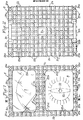
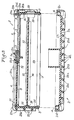
- the housing shown in Figures 1 to 3 comprises an upper part 1 and a lower part 2 of a moldable elastomeric material.
- Parts 1 and 2 can be assembled to one another, detachably, by elastic snap-fastening, by means of a rib 3 and a groove 4, the cross sections of which have shapes complementary to one of the 'other.
- the rib 3 and the groove 4 have, in cross section, the shape of a bulb.
- the rib 3 is shown integral with the upper part 1 and the groove 4 formed in the lower part 2, one could of course have the opposite arrangement.
- the upper part 1 In its upper wall 1a, the upper part 1 has two large rectangular openings 5 and 6. Two plates 7 and 8 are embedded respectively in rebates 9 and 11, in the form of deep grooves, provided in the periphery of each of the openings 5 and 6.
- the plate 7 is a protective glass made of safety glass or of an unbreakable transparent plastic material.
- the plate 8 is made of metal or of a semi-rigid plastic material. As shown in Figure 1, the plate 8 has at least one hole 12 for the passage of a rotary switch for selecting functions and / or calibers (only the operating button 13 of the rotary switch has been shown in phantom in Figure 1) and it includes on its upper side indications relating to the functions and / or calibers of the measuring device.
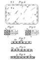
- each of the two plates 7 and 8 has several cavities 14 as shown in FIG. 4 for the plate 7.
- the cavities 14 have for example an oblong section.
- the cavities 14 are preferably constituted by through holes as shown in FIG. 5, they can also be constituted by deep blind holes as shown in FIG. 6.
- the upper part 1 of the housing is produced by overmolding on the plates 7 and 8, so that the elastomeric material fills the cavities 14 of the plates 7 and 8 during molding and thus ensures a practically undetachable connection between each of the plates 7 and 8 and the elastomeric material constituting the upper part 1 of the housing.
- an injection molding technique can be used for molding.
- the elastomeric material used can be a thermoplastic elastomer, such as for example a copolymer of styrene-butadiene-styrene (SBS) having. a shore hardness of between 60 and 70. Good results have been obtained with an elastomeric material sold by the company F. CHEVASSUS under the commercial reference "Fervanflex CT 1 060 or 1 070".
- SBS styrene-butadiene-styrene
- At least two opposite side walls 1b and 1c, preferably the three side walls 1b, 1c and 1d of the upper part 1 of the housing have, on their inner face, two ribs 15 and 16, which are parallel to each other and to the wall upper 1a and which form between them an elastic rebate in which is embedded a plate 17 with printed circuits.
- the lower rib 16 has a roughly triangular cross section, to facilitate insertion by elastic snap-fastening of the edges of the plate 17 into the rebate formed between the two ribs 15 and 16.
- the fourth side wall 1e of the upper part 1 has several holes 18 (a single hole is visible in Figure 3) forming bushings for sockets or connection terminals 19 electrically connected to the printed circuits of the plate 17, for the connection of the device measurement to external circuits.
- the plate 17 carries the aforementioned rotary switch, the various electrical and electronic components of the measurement circuits and the measurement indicator (galvanometer or digital display), the latter being placed below the transparent plate 7 .
- Each of the walls 1a to 1e and 2a to 2e of the upper and lower parts 1 and 2 of the housing comprises, on its outer face, a network of elements 21 in relief, made of elastomeric material, forming shock absorbers.
- the elements 21 in relief on the same outer face have different heights with respect to the outer face considered.
- the elements 21 in relief may include a first group of ribs 21a and 21b which are mutually parallel and alternately high and low, and a second group of ribs 21c and 21d, alternately high and low, which are mutually parallel and intersect at right angles the ribs 21a and 21b of the first group.
- the ribs 21a and 21b or 21c and 21d are shown alternately high and low, we can provide another distribution for the high and low ribs according to the desired degree of elasticity.
- two low ribs 21 b (and / or 21d) can be provided for a high rib 21a (and / or 21c) as shown in FIG. 7 or, conversely, two high ribs 21a (and / or 21c) for a low rib 21b (and / or 21d) as shown in FIG. 8.
- ribs 21 having heights such that the vertices of adjacent ribs are on a broken line or on a sinusoid 22 as shown in Figure 9.
- the embodiment of the housing which has been described above has been given by way of purely indicative and in no way limiting, and that numerous modifications can be easily made by those skilled in the art. art without departing from the scope of the present invention.
- the cavities 14 provided in the periphery of each of the two plates 7 and 8 instead of being constituted by holes, can be constituted by notches with T-section or dovetail, formed in the edges of the plates 7 and 8.
- the elements 21 in relief can be produced in the form of cylindrical or frustoconical studs of different heights.
- the side walls 1b to 1e of the upper part 1 can be shorter and the side walls 2b to 2e of the lower part 2 higher than those shown in FIG. 3.
- the ribs 15 and 16 can be formed on the inner faces of the side walls 2a to 2d of the lower part 2.
Landscapes
- Mechanical Engineering (AREA)
- Physics & Mathematics (AREA)
- General Physics & Mathematics (AREA)
- Engineering & Computer Science (AREA)
- Chemical & Material Sciences (AREA)
- Composite Materials (AREA)
- Details Of Measuring And Other Instruments (AREA)
- Casings For Electric Apparatus (AREA)
- Packages (AREA)
- Vibration Dampers (AREA)
- Measurement Of Radiation (AREA)
- Measuring Or Testing Involving Enzymes Or Micro-Organisms (AREA)
- Measuring Fluid Pressure (AREA)
- Pens And Brushes (AREA)
- Sampling And Sample Adjustment (AREA)
Claims (10)
Priority Applications (1)
| Application Number | Priority Date | Filing Date | Title |
|---|---|---|---|
| AT84402359T ATE40017T1 (de) | 1983-11-30 | 1984-11-20 | Antistossbehaelter, insbesondere fuer tragbares messgeraet. |
Applications Claiming Priority (2)
| Application Number | Priority Date | Filing Date | Title |
|---|---|---|---|
| FR8319094A FR2555757B1 (fr) | 1983-11-30 | 1983-11-30 | Boitier antichoc, notamment pour appareil portatif de mesure |
| FR8319094 | 1983-11-30 |
Publications (2)
| Publication Number | Publication Date |
|---|---|
| EP0176644A1 EP0176644A1 (de) | 1986-04-09 |
| EP0176644B1 true EP0176644B1 (de) | 1989-01-11 |
Family
ID=9294678
Family Applications (1)
| Application Number | Title | Priority Date | Filing Date |
|---|---|---|---|
| EP84402359A Expired EP0176644B1 (de) | 1983-11-30 | 1984-11-20 | Antistossbehälter, insbesondere für tragbares Messgerät |
Country Status (5)
| Country | Link |
|---|---|
| US (1) | US4557383A (de) |
| EP (1) | EP0176644B1 (de) |
| AT (1) | ATE40017T1 (de) |
| DE (1) | DE3476135D1 (de) |
| FR (1) | FR2555757B1 (de) |
Families Citing this family (8)
| Publication number | Priority date | Publication date | Assignee | Title |
|---|---|---|---|---|
| US4860901A (en) * | 1986-04-03 | 1989-08-29 | Brown, Boveri & Cie Ag | Housing with a flexible shock protector for a portable measuring instrument |
| DE3633856A1 (de) * | 1986-04-03 | 1987-10-08 | Bbc Brown Boveri & Cie | Gehaeuse fuer ein tragbares messgeraet |
| FR2646953B1 (fr) * | 1989-05-12 | 1991-08-30 | Itt Composants Instr | Boitier, notamment pour un appareil de mesures electriques, equipe d'une poignee amovible |
| US5310053A (en) * | 1992-03-20 | 1994-05-10 | Shape Inc. | Telescoping compact disc holder and foldable cover |
| DE4340177A1 (de) * | 1993-11-25 | 1995-06-01 | Mannesmann Kienzle Gmbh | Meßwertgeber |
| US6036007A (en) * | 1996-08-08 | 2000-03-14 | Alejandro; Miriam L. | Transportation case for a heavy object |
| ATE367730T1 (de) * | 2005-04-01 | 2007-08-15 | Knuerr Ag | Lagerungs-anordnung |
| DE102013114142A1 (de) * | 2013-12-16 | 2015-06-18 | Endress + Hauser Wetzer Gmbh + Co. Kg | Sensorvorrichtung und Sensoranordnung mit einer Sensorvorrichtung |
Family Cites Families (8)
| Publication number | Priority date | Publication date | Assignee | Title |
|---|---|---|---|---|
| GB493009A (en) * | 1937-08-13 | 1938-09-30 | Moulded Products Ltd | Improved method and means of glazing instrument cases and other structures having a transparent panel |
| FR1104477A (fr) * | 1954-05-10 | 1955-11-21 | Savoisienne Pour L Ind Ardoisi | Procédé d'encadrement en matière moulable d'une plaque, une ardoise en particulier, et objet obtenu par sa mise en oeuvre |
| US2961108A (en) * | 1957-12-19 | 1960-11-22 | Frances S Johnson | Magnifying cap for medicine bottle |
| FR2188908A5 (de) * | 1972-06-01 | 1974-01-18 | D Ppareill Const | |
| US3972239A (en) * | 1972-09-20 | 1976-08-03 | Robertshaw Controls Company | Gage construction and parts therefor or the like |
| US4112283A (en) * | 1977-03-18 | 1978-09-05 | James Lathrop | Distributor cap and dust shield with hermetic sealing and moisture detection apparatus |
| DE2742111A1 (de) * | 1977-09-19 | 1979-03-29 | Vdo Schindling | Anzeigeinstrument, insbesondere fuer fahrzeuge |
| US4245749A (en) * | 1979-01-10 | 1981-01-20 | General American Transportation Corporation | Safety device |
-
1983
- 1983-11-30 FR FR8319094A patent/FR2555757B1/fr not_active Expired
-
1984
- 1984-11-20 DE DE8484402359T patent/DE3476135D1/de not_active Expired
- 1984-11-20 EP EP84402359A patent/EP0176644B1/de not_active Expired
- 1984-11-20 AT AT84402359T patent/ATE40017T1/de not_active IP Right Cessation
- 1984-11-28 US US06/675,936 patent/US4557383A/en not_active Expired - Fee Related
Also Published As
| Publication number | Publication date |
|---|---|
| FR2555757B1 (fr) | 1986-07-11 |
| EP0176644A1 (de) | 1986-04-09 |
| US4557383A (en) | 1985-12-10 |
| FR2555757A1 (fr) | 1985-05-31 |
| ATE40017T1 (de) | 1989-01-15 |
| DE3476135D1 (en) | 1989-02-16 |
Similar Documents
| Publication | Publication Date | Title |
|---|---|---|
| EP0176644B1 (de) | Antistossbehälter, insbesondere für tragbares Messgerät | |
| FR2461971A1 (fr) | Montre equipee d'un support | |
| FR2631738A1 (fr) | Module de protection pour electro-aimant de contacteur | |
| FR2666936A1 (fr) | Fiche isolante encliquetable dans un boitier de connecteurs electriques. | |
| FR2920051A1 (fr) | Multimetre numerique avec un agencement d'etencheite de logement | |
| FR2597387A3 (fr) | Couteau a usages domestiques et professionnels avec manche revetu de materiau elastomere. | |
| EP1590862A1 (de) | Elektrischer verbinder | |
| EP0739064A1 (de) | Herstellungsverfahren für modulare Verbindereinheit und für die so erhaltene elektrische Verbindung | |
| FR2630846A1 (fr) | Support a deux plaques assemblees pour presenter des informations et/ou des objets divers | |
| FR2529033A1 (de) | ||
| FR2652754A1 (fr) | Dispositif de guidage lateral d'une chaussure de ski de fond. | |
| WO2002082587A1 (fr) | Connecteur pour montage en surface de circuit imprime et procede de fabrication | |
| EP1724888B1 (de) | Modulares Gehäuse für elektrische Geräte | |
| FR2519612A1 (fr) | Emballage avec plateau et couvercle pour oeufs | |
| EP0512929B1 (de) | Bodenrahmen für elektrischen Kasten | |
| BE477091A (de) | ||
| FR2669545A1 (fr) | Raquette de tennis de table ou similaire. | |
| BE897908A (fr) | Ponceuse mecanique portative dite "ponceuse vibrante" | |
| EP0750388B1 (de) | Wechselstromgenerator für ein Kraftfahrzeug mit einer Bürstentragplatte mit umgossenem Entstörkondensator | |
| FR2477835A3 (fr) | Dispositif electrique de vaporisation d'une substance active volatile | |
| FR2667232A1 (fr) | Plateau, destine notamment a l'usage dans la restauration. | |
| FR2722315A1 (fr) | Procede pour la fabrication d'une carte electronique sans contact comportant une pile remplacable | |
| FR2674820A1 (fr) | Barquette de conditionnement de morceaux de viande presentes a plat. | |
| FR2825685A1 (fr) | Caisse reutilisable pour le transport de pieces | |
| FR2600157A1 (fr) | Echelle graduee pour mesureur de niveaux |
Legal Events
| Date | Code | Title | Description |
|---|---|---|---|
| PUAI | Public reference made under article 153(3) epc to a published international application that has entered the european phase |
Free format text: ORIGINAL CODE: 0009012 |
|
| 17P | Request for examination filed |
Effective date: 19851227 |
|
| AK | Designated contracting states |
Kind code of ref document: A1 Designated state(s): AT DE GB IT NL |
|
| 17Q | First examination report despatched |
Effective date: 19880629 |
|
| ITF | It: translation for a ep patent filed | ||
| GRAA | (expected) grant |
Free format text: ORIGINAL CODE: 0009210 |
|
| AK | Designated contracting states |
Kind code of ref document: B1 Designated state(s): AT DE GB IT NL |
|
| REF | Corresponds to: |
Ref document number: 40017 Country of ref document: AT Date of ref document: 19890115 Kind code of ref document: T |
|
| GBT | Gb: translation of ep patent filed (gb section 77(6)(a)/1977) | ||
| REF | Corresponds to: |
Ref document number: 3476135 Country of ref document: DE Date of ref document: 19890216 |
|
| PLBE | No opposition filed within time limit |
Free format text: ORIGINAL CODE: 0009261 |
|
| STAA | Information on the status of an ep patent application or granted ep patent |
Free format text: STATUS: NO OPPOSITION FILED WITHIN TIME LIMIT |
|
| 26N | No opposition filed | ||
| PGFP | Annual fee paid to national office [announced via postgrant information from national office to epo] |
Ref country code: AT Payment date: 19901031 Year of fee payment: 7 |
|
| PGFP | Annual fee paid to national office [announced via postgrant information from national office to epo] |
Ref country code: NL Payment date: 19901130 Year of fee payment: 7 |
|
| PG25 | Lapsed in a contracting state [announced via postgrant information from national office to epo] |
Ref country code: AT Effective date: 19911120 |
|
| PG25 | Lapsed in a contracting state [announced via postgrant information from national office to epo] |
Ref country code: NL Effective date: 19920601 |
|
| NLV4 | Nl: lapsed or anulled due to non-payment of the annual fee | ||
| PGFP | Annual fee paid to national office [announced via postgrant information from national office to epo] |
Ref country code: GB Payment date: 19931026 Year of fee payment: 10 |
|
| PGFP | Annual fee paid to national office [announced via postgrant information from national office to epo] |
Ref country code: DE Payment date: 19931028 Year of fee payment: 10 |
|
| ITTA | It: last paid annual fee | ||
| PG25 | Lapsed in a contracting state [announced via postgrant information from national office to epo] |
Ref country code: GB Effective date: 19941120 |
|
| GBPC | Gb: european patent ceased through non-payment of renewal fee |
Effective date: 19941120 |
|
| PG25 | Lapsed in a contracting state [announced via postgrant information from national office to epo] |
Ref country code: DE Effective date: 19950801 |