EP0176644B1 - Shock-resistant container, particularly for a portable measurement apparatus - Google Patents
Shock-resistant container, particularly for a portable measurement apparatus Download PDFInfo
- Publication number
- EP0176644B1 EP0176644B1 EP84402359A EP84402359A EP0176644B1 EP 0176644 B1 EP0176644 B1 EP 0176644B1 EP 84402359 A EP84402359 A EP 84402359A EP 84402359 A EP84402359 A EP 84402359A EP 0176644 B1 EP0176644 B1 EP 0176644B1
- Authority
- EP
- European Patent Office
- Prior art keywords
- plate
- elastomeric material
- ribs
- box according
- cavities
- Prior art date
- Legal status (The legal status is an assumption and is not a legal conclusion. Google has not performed a legal analysis and makes no representation as to the accuracy of the status listed.)
- Expired
Links
Images
Classifications
-
- B—PERFORMING OPERATIONS; TRANSPORTING
- B29—WORKING OF PLASTICS; WORKING OF SUBSTANCES IN A PLASTIC STATE IN GENERAL
- B29C—SHAPING OR JOINING OF PLASTICS; SHAPING OF MATERIAL IN A PLASTIC STATE, NOT OTHERWISE PROVIDED FOR; AFTER-TREATMENT OF THE SHAPED PRODUCTS, e.g. REPAIRING
- B29C37/00—Component parts, details, accessories or auxiliary operations, not covered by group B29C33/00 or B29C35/00
- B29C37/0078—Measures or configurations for obtaining anchoring effects in the contact areas between layers
- B29C37/0082—Mechanical anchoring
- B29C37/0085—Mechanical anchoring by means of openings in the layers
-
- B—PERFORMING OPERATIONS; TRANSPORTING
- B29—WORKING OF PLASTICS; WORKING OF SUBSTANCES IN A PLASTIC STATE IN GENERAL
- B29C—SHAPING OR JOINING OF PLASTICS; SHAPING OF MATERIAL IN A PLASTIC STATE, NOT OTHERWISE PROVIDED FOR; AFTER-TREATMENT OF THE SHAPED PRODUCTS, e.g. REPAIRING
- B29C70/00—Shaping composites, i.e. plastics material comprising reinforcements, fillers or preformed parts, e.g. inserts
- B29C70/68—Shaping composites, i.e. plastics material comprising reinforcements, fillers or preformed parts, e.g. inserts by incorporating or moulding on preformed parts, e.g. inserts or layers, e.g. foam blocks
- B29C70/74—Moulding material on a relatively small portion of the preformed part, e.g. outsert moulding
- B29C70/76—Moulding on edges or extremities of the preformed part
- B29C70/763—Moulding on edges or extremities of the preformed part the edges being disposed in a substantial flat plane
-
- G—PHYSICS
- G01—MEASURING; TESTING
- G01D—MEASURING NOT SPECIALLY ADAPTED FOR A SPECIFIC VARIABLE; ARRANGEMENTS FOR MEASURING TWO OR MORE VARIABLES NOT COVERED IN A SINGLE OTHER SUBCLASS; TARIFF METERING APPARATUS; MEASURING OR TESTING NOT OTHERWISE PROVIDED FOR
- G01D11/00—Component parts of measuring arrangements not specially adapted for a specific variable
- G01D11/24—Housings ; Casings for instruments
-
- G—PHYSICS
- G01—MEASURING; TESTING
- G01R—MEASURING ELECTRIC VARIABLES; MEASURING MAGNETIC VARIABLES
- G01R1/00—Details of instruments or arrangements of the types included in groups G01R5/00 - G01R13/00 and G01R31/00
- G01R1/02—General constructional details
- G01R1/04—Housings; Supporting members; Arrangements of terminals
-
- B—PERFORMING OPERATIONS; TRANSPORTING
- B29—WORKING OF PLASTICS; WORKING OF SUBSTANCES IN A PLASTIC STATE IN GENERAL
- B29L—INDEXING SCHEME ASSOCIATED WITH SUBCLASS B29C, RELATING TO PARTICULAR ARTICLES
- B29L2031/00—Other particular articles
- B29L2031/712—Containers; Packaging elements or accessories, Packages
- B29L2031/7162—Boxes, cartons, cases
Definitions
- the present invention relates to an impact-resistant housing, in particular for a portable measuring device, of the type comprising two parts which can be assembled together, made of a moldable elastomeric material, one of the two parts comprising a main wall having an opening in the periphery of which is formed an elastic rebate frame, and a plate of a material significantly more rigid than said elastomeric material, which is embedded in said rebate.
- a shockproof housing of this type is already known from French patent No. 2 188 908 of the applicant.
- Several difficulties have been encountered in the production of this known housing.
- a first difficulty lies in obtaining a sufficient connection between the parts of the case made of an elastomeric material, on the one hand, and the rigid or semi-rigid parts which it contains, on the other hand. This is particularly the case for the protective glass on the dial of the measuring device.
- the protective glass tends to disengage from the abovementioned rebate, or even to come out completely rebate.
- a second difficulty resides in the positioning and the connection to the housing of the internal plate carrying the components of the measuring device (electrical components, electronic components, measurement indicator - galvanometer or digital display).
- a third difficulty lies in obtaining a housing whose walls have an elasticity which varies in thickness.
- French patent n ° 2188 908 provides elastic elements in relief on the faces of the housing, these elastic elements in relief being hollowed out externally or internally, the cavities thus obtained being optionally closed in order to obtain a multitude of sealed volumes. , filled with air and perfectly elastic.
- 2 188 908 consists in using a plastic or elastomer which itself has a variable elasticity in its thickness, so as to have a relatively high hardness and a lower elasticity on the inner side and , on the contrary, relatively low hardness and higher elasticity on the outside.
- the main object of the present invention is to improve the connection between the above-mentioned rigid or semi-rigid plate and the part made of elastomeric material of the housing.
- the present invention also aims to provide a number of constructive arrangements facilitating the production of an impact-resistant housing, while simultaneously improving its qualities of robustness.
- the shockproof housing according to the present invention is characterized in that said plate has several cavities in its peripheral region embedded in the rebate, and in that said part of the housing which comprises the opening is produced by overmolding on said plate , so that the elastomeric material fills said cavities of the plate during molding.
- the housing shown in Figures 1 to 3 comprises an upper part 1 and a lower part 2 of a moldable elastomeric material.
- Parts 1 and 2 can be assembled to one another, detachably, by elastic snap-fastening, by means of a rib 3 and a groove 4, the cross sections of which have shapes complementary to one of the 'other.
- the rib 3 and the groove 4 have, in cross section, the shape of a bulb.
- the rib 3 is shown integral with the upper part 1 and the groove 4 formed in the lower part 2, one could of course have the opposite arrangement.
- the upper part 1 In its upper wall 1a, the upper part 1 has two large rectangular openings 5 and 6. Two plates 7 and 8 are embedded respectively in rebates 9 and 11, in the form of deep grooves, provided in the periphery of each of the openings 5 and 6.
- the plate 7 is a protective glass made of safety glass or of an unbreakable transparent plastic material.
- the plate 8 is made of metal or of a semi-rigid plastic material. As shown in Figure 1, the plate 8 has at least one hole 12 for the passage of a rotary switch for selecting functions and / or calibers (only the operating button 13 of the rotary switch has been shown in phantom in Figure 1) and it includes on its upper side indications relating to the functions and / or calibers of the measuring device.
- each of the two plates 7 and 8 has several cavities 14 as shown in FIG. 4 for the plate 7.
- the cavities 14 have for example an oblong section.
- the cavities 14 are preferably constituted by through holes as shown in FIG. 5, they can also be constituted by deep blind holes as shown in FIG. 6.
- the upper part 1 of the housing is produced by overmolding on the plates 7 and 8, so that the elastomeric material fills the cavities 14 of the plates 7 and 8 during molding and thus ensures a practically undetachable connection between each of the plates 7 and 8 and the elastomeric material constituting the upper part 1 of the housing.
- an injection molding technique can be used for molding.
- the elastomeric material used can be a thermoplastic elastomer, such as for example a copolymer of styrene-butadiene-styrene (SBS) having. a shore hardness of between 60 and 70. Good results have been obtained with an elastomeric material sold by the company F. CHEVASSUS under the commercial reference "Fervanflex CT 1 060 or 1 070".
- SBS styrene-butadiene-styrene
- At least two opposite side walls 1b and 1c, preferably the three side walls 1b, 1c and 1d of the upper part 1 of the housing have, on their inner face, two ribs 15 and 16, which are parallel to each other and to the wall upper 1a and which form between them an elastic rebate in which is embedded a plate 17 with printed circuits.
- the lower rib 16 has a roughly triangular cross section, to facilitate insertion by elastic snap-fastening of the edges of the plate 17 into the rebate formed between the two ribs 15 and 16.
- the fourth side wall 1e of the upper part 1 has several holes 18 (a single hole is visible in Figure 3) forming bushings for sockets or connection terminals 19 electrically connected to the printed circuits of the plate 17, for the connection of the device measurement to external circuits.
- the plate 17 carries the aforementioned rotary switch, the various electrical and electronic components of the measurement circuits and the measurement indicator (galvanometer or digital display), the latter being placed below the transparent plate 7 .
- Each of the walls 1a to 1e and 2a to 2e of the upper and lower parts 1 and 2 of the housing comprises, on its outer face, a network of elements 21 in relief, made of elastomeric material, forming shock absorbers.
- the elements 21 in relief on the same outer face have different heights with respect to the outer face considered.
- the elements 21 in relief may include a first group of ribs 21a and 21b which are mutually parallel and alternately high and low, and a second group of ribs 21c and 21d, alternately high and low, which are mutually parallel and intersect at right angles the ribs 21a and 21b of the first group.
- the ribs 21a and 21b or 21c and 21d are shown alternately high and low, we can provide another distribution for the high and low ribs according to the desired degree of elasticity.
- two low ribs 21 b (and / or 21d) can be provided for a high rib 21a (and / or 21c) as shown in FIG. 7 or, conversely, two high ribs 21a (and / or 21c) for a low rib 21b (and / or 21d) as shown in FIG. 8.
- ribs 21 having heights such that the vertices of adjacent ribs are on a broken line or on a sinusoid 22 as shown in Figure 9.
- the embodiment of the housing which has been described above has been given by way of purely indicative and in no way limiting, and that numerous modifications can be easily made by those skilled in the art. art without departing from the scope of the present invention.
- the cavities 14 provided in the periphery of each of the two plates 7 and 8 instead of being constituted by holes, can be constituted by notches with T-section or dovetail, formed in the edges of the plates 7 and 8.
- the elements 21 in relief can be produced in the form of cylindrical or frustoconical studs of different heights.
- the side walls 1b to 1e of the upper part 1 can be shorter and the side walls 2b to 2e of the lower part 2 higher than those shown in FIG. 3.
- the ribs 15 and 16 can be formed on the inner faces of the side walls 2a to 2d of the lower part 2.
Abstract
Description
La présente invention concerne un boîtier antichoc, notamment pour appareil portatif de mesure, du type comprenant deux parties assemblables l'une à l'autre, en une matière élastomère moulable, l'une des deux parties comportant une paroi principale ayant une ouverture dans la périphérie de laquelle est formée une feuillure élastique d'encadrement, et une plaque en une matière nettement plus rigide que ladite matière élastomère, qui est encastrée dans ladite feuillure.The present invention relates to an impact-resistant housing, in particular for a portable measuring device, of the type comprising two parts which can be assembled together, made of a moldable elastomeric material, one of the two parts comprising a main wall having an opening in the periphery of which is formed an elastic rebate frame, and a plate of a material significantly more rigid than said elastomeric material, which is embedded in said rebate.
On connaît déjà un boîtier antichoc de ce type par le brevet français n° 2 188 908 de la demanderesse. Plusieurs difficultés ont été rencontrées dans la réalisation de ce boîtier connu. Une première difficulté réside dans l'obtention d'une liaison suffisante entre les parties du boîtier en une matière élastomère, d'une part, et les parties rigides ou semi-rigides qu'il contient, d'autre part. C'est le cas notamment pour la glace de protection du cadran de l'appareil de mesure. En effet, avec le boîtier antérieurement connu, on a constaté que, en cas de choc particulièrement sévère, par exemple en cas de chute sur le sol, la glace de protection a tendance à se déboîter de la feuillure susmentionnée, voire même à sortir complètement de la feuillure. Une seconde difficulté réside dans le positionnement et la liaison au boîtier de la platine intérieure portant les composants de l'appareil de mesure (composants électriques, composants électroniques, indicateur de mesure - galvanomètre ou afficheur numérique). Une troisième difficulté réside dans l'obtention d'um boîtier dont les parois présentent une élasticité variable en épaisseur. A cet effet, le brevet français n° 2188 908 prévoit des éléments élastiques en relief sur les faces du boîtier, ces éléments élastiques en relief étant évidés extérieurement ou intérieurement, les cavités ainsi obtenues étant éventuellement obturées afin d'obtenir une multitude de volumes étanches, remplis d'air et parfaitement élastiques. Une autre solution proposée par le brevet français n° 2 188 908 consiste à utiliser une matière plastique ou élastomère qui a elle-même une élasticité variable dans son épaisseur, de manière à avoir une dureté relativement élevée et une élasticité plus faible du côté intérieur et, au contraire, une dureté relativement faible et une élasticité plus élevée du côté extérieur. Ces deux solutions se sont révélées difficiles à réaliser en pratique.A shockproof housing of this type is already known from French patent No. 2 188 908 of the applicant. Several difficulties have been encountered in the production of this known housing. A first difficulty lies in obtaining a sufficient connection between the parts of the case made of an elastomeric material, on the one hand, and the rigid or semi-rigid parts which it contains, on the other hand. This is particularly the case for the protective glass on the dial of the measuring device. In fact, with the previously known housing, it has been found that, in the event of a particularly severe impact, for example in the event of a fall to the ground, the protective glass tends to disengage from the abovementioned rebate, or even to come out completely rebate. A second difficulty resides in the positioning and the connection to the housing of the internal plate carrying the components of the measuring device (electrical components, electronic components, measurement indicator - galvanometer or digital display). A third difficulty lies in obtaining a housing whose walls have an elasticity which varies in thickness. To this end, French patent n ° 2188 908 provides elastic elements in relief on the faces of the housing, these elastic elements in relief being hollowed out externally or internally, the cavities thus obtained being optionally closed in order to obtain a multitude of sealed volumes. , filled with air and perfectly elastic. Another solution proposed by French Patent No. 2 188 908 consists in using a plastic or elastomer which itself has a variable elasticity in its thickness, so as to have a relatively high hardness and a lower elasticity on the inner side and , on the contrary, relatively low hardness and higher elasticity on the outside. These two solutions have proven difficult to achieve in practice.
La présente invention a principalement pour but d'améliorer la liaison entre la plaque rigide ou semi-rigide susmentionnée et la partie en matière élastomère du boîtier.The main object of the present invention is to improve the connection between the above-mentioned rigid or semi-rigid plate and the part made of elastomeric material of the housing.
La présente invention a également pour but de fournir un certain nombre d'aménagements constructifs facilitant la réalisation d'un boîtier antichoc, tout en améliorant simultanément ses qualités de robustesse.The present invention also aims to provide a number of constructive arrangements facilitating the production of an impact-resistant housing, while simultaneously improving its qualities of robustness.
A cet effet, le boîtier antichoc selon la présente invention est caractérisé en ce que ladite plaque comporte plusieurs cavités dans sa région périphérique encastrée dans la feuillure, et en ce que ladite partie du boîtier qui comporte l'ouverture est réalisée par surmoulage sur ladite plaque, de telle façon que la matière élastomère remplisse lesdites cavités de la plaque lors du moulage.To this end, the shockproof housing according to the present invention is characterized in that said plate has several cavities in its peripheral region embedded in the rebate, and in that said part of the housing which comprises the opening is produced by overmolding on said plate , so that the elastomeric material fills said cavities of the plate during molding.
De cette manière, on obtient une liaison efficace entre la plaque et la partie en matière élastomère du boîtier.In this way, an effective connection is obtained between the plate and the elastomeric part of the housing.
D'autres caractéristiques et avantages de la présente invention ressortiront au cours de la description qui va suivre d'une forme d'exécution du boîtier antichoc.
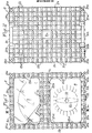
- Les figures 1 et 2 sont des vues, respectivement de dessus et de dessous, du boîtier antichoc pour un appareil de mesure.
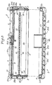
- La figure 3 est une vue en coupe suivant la ligne III-III de la figure 1 montrant, à plus grande échelle, les deux parties du boîtier détachées l'une de l'autre.
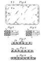
- La figure 4 est une vue de dessus de la glace de protection du cadran du boîtier de la figure 1.
- La figure 5 est une vue partielle en coupe suivant la ligne V-V de la figure 4, montrant, à plus grande échelle, un détail de la liaison entre la glace de protection et la partie en matière élastomère du boîtier.
- La figure 6 est une vue similaire à la figure 5, montrant une variante.
- Les figures 7 à 9 sont des vues partielles en coupe, montrant d'autres dispositions possibles pour les éléments élastiques en relief du boîtier.
- Figures 1 and 2 are views, respectively from above and from below, of the shockproof housing for a measuring device.
- Figure 3 is a sectional view along line III-III of Figure 1 showing, on a larger scale, the two parts of the housing detached from each other.
- FIG. 4 is a top view of the protective glass of the dial of the housing of FIG. 1.
- Figure 5 is a partial sectional view along line VV of Figure 4, showing, on a larger scale, a detail of the connection between the protective glass and the elastomeric part of the housing.
- Figure 6 is a view similar to Figure 5 showing a variant.
- Figures 7 to 9 are partial sectional views showing other possible arrangements for the raised elastic elements of the housing.
Le boîtier représenté sur les figures 1 à 3 comprend une partie supérieure 1 et une partie inférieure 2 en une matière élastomère moulable. Les parties 1 et 2 peuvent être assemblées l'une à l'autre, de manière détachable, par encliquetage élastique, au moyen d'une nervure 3 et d'une rainure 4 dont les sections transversales ont des formes complémentaires l'une de l'autre. Comme montré dans la figure 3, la nervure 3 et la rainure 4 ont, vue en coupe transversale, la forme d'un bulbe. Bien que dans la figure 3, la nervure 3 soit représentée solidaire de la partie supérieure 1 et la rainure 4 formée dans la partie inférieure 2, on pourrait bien entendu avoir la disposition inverse.The housing shown in Figures 1 to 3 comprises an
Dans sa paroi supérieure 1a, la partie supérieure 1 comporte deux larges ouvertures rectangulaires 5 et 6. Deux plaques 7 et 8 sont encastrées respectivement dans des feuillures 9 et 11, en forme de profondes rainures, prévues dans la périphérie de chacune des ouvertures 5 et 6. La plaque 7 est une glace de protection en verre de sécurité ou en une matière plastique transparente incassable. La plaque 8 est en métal ou en une matière plastique semi-rigide. Comme montré dans la figure 1, la plaque 8 comporte au moins un trou 12 pour le passage d'un commutateur rotatif de sélection de fonctions et/ou de calibres (seul le bouton de manoeuvre 13 du commutateur rotatif a été représenté en trait mixte dans la figure 1) et elle comporte sur sa face supérieure des indications relatives aux fonctions et/ou aux calibres de l'appareil de mesure.In its upper wall 1a, the
Afin d'éviter que les plaques 7 et 8 sortent de leurs feuillures respectives 9 et 11 en cas de choc sévère, chacune des deux plaques 7 et 8 comporte plusieurs cavités 14 comme cela est montré dans la figure 4 pour la plaque 7. Les cavités 14 ont par exemple une section de forme oblongue. Bien que les cavités 14 soient de préférence constituées par des trous traversants comme montré dans la figure 5, elles peuvent être aussi constituées par des trous borgnes profonds comme montré dans la figure 6. La partie supérieure 1 du boîtier est réalisée par surmoulage sur les plaques 7 et 8, de telle façon que la matière élastomère remplisse les cavités 14 des plaques 7 et 8 lors du moulage et assure ainsi une liaison pratiquement indétachable entre chacune des plaques 7 et 8 et la matière élastomère constituant la partie supérieure 1 du boîtier. Pour le moulage, on peut utiliser une technique de moulage par injection. La matière élastomère utilisée peut être un élastomère thermoplastique, comme par exemple un copoiymère de styrène-butadiène-styrène (SBS) ayant. une dureté shore comprise entre 60 et 70. De bons résultats ont été obtenus avec une matière élastomère vendue par la Société F. CHEVASSUS sous la référence commerciale « Fervanflex CT 1 060 ou 1 070 ».In order to prevent the
Au moins deux parois latérales opposées 1b et 1c, de préférence les trois parois latérales lb, 1c et 1d de la partie supérieure 1 du boîtier comportent, sur leur face intérieure, deux nervures 15 et 16, qui sont parallèles entre elles et à la paroi supérieure 1a et qui forment entre elles une feuillure élastique dans laquelle est encastrée une plaque 17 à circuits imprimés. Comme montré dans la figure 3, la nervure inférieure 16 a une section transversale en gros triangulaire, pour faciliter l'insertion par encliquetage élastique des bords de la plaque 17 dans la feuillure formée entre les deux nervures 15 et 16. La quatrième paroi latérale 1e de la partie supérieure 1 comporte plusieurs trous 18 (un seul trou est visible dans la figure 3) formant des traversées pour des douilles ou des bornes de raccordement 19 reliées électriquement aux circuits imprimés de la plaque 17, pour le branchement de l'appareil de mesure à des circuits extérieurs. Outre les circuits imprimés, la plaque 17 porte le commutateur rotatif susmentionné, les divers composants électriques et électroniques des circuits de mesure'et l'indicateur de mesure (galvanomètre ou afficheur numérique), ce dernier étant placé au-dessous de la plaque transparente 7.At least two
Chacune des parois 1a à 1e et 2a à 2e des parties supérieure et inférieure 1 et 2 du boîtier comporte, sur sa face extérieure, un réseau d'éléments 21 en relief, en matière élastomère, formant des amortisseurs de choc. Les éléments 21 en relief d'une même face extérieure ont des hauteurs différentes par rapport à la face extérieure considérée. Comme montré dans les figures 1 à 3, les éléments 21 en relief peuvent comprendre un premier groupe de nervures 21a et 21 b parallèles entre elles et alternativement haute et basse, et un second groupe de nervures 21c et 21d, alternativement haute et basse, qui sont parallèles entre elles et qui intersectent à angles droits les nervures 21a et 21 b du premier groupe. Ainsi, en cas de choc, par exemple lorsque l'appareil de mesure tombe au sol, le choc est tout d'abord amorti par les rainures 21a et 21c les plus saillantes, puis les nervures les moins saillantes 21b et 21d entrent aussi en action pour amortir le choc après que les nervures les plus saillantes ont été comprimées ou écrasées d'une quantité égale à la différence de hauteur des nervures. On obtient ainsi, de manière simple et facilement réalisable, une élasticité variable en fonction de l'épaisseur. Comme montré dans les figures 1 et 2, des nervures 21e, orientées à 45° par rapport aux nervures 21a à 21c, sont aussi prévues aux quatre angles du boîtier.Each of the walls 1a to 1e and 2a to 2e of the upper and
Bien que dans les figures 1 à 3, les nervures 21a et 21 b ou 21 c et 21 d soient représentées alternativement haute et basse, on peut prévoir une autre distribution pour les nervures hautes et basses selon le degré d'élasticité désirée. Par exemple, on peut prévoir deux nervures basses 21 b (et/ou 21d) pour une nervure haute 21a (et/ou 21c) comme montré dans la figure 7 ou, inversement, deux nervures hautes 21a (et/ou 21c) pour une nervure basse 21b (et/ou 21d) comme montré dans la figure 8. Afin d'obtenir une élasticité variant de manière encore plus progressive dans le sens de l'épaisseur, il est possible de prévoir des nervures 21 ayant des hauteurs telles que les sommets des nervures adjacentes se trouvent sur une ligne brisée ou sur une sinusoïde 22 comme montré dans la figure 9.Although in Figures 1 to 3, the
Il est du reste bien entendu que la forme d'exécution du boîtier qui a été décrite ci-dessus a été donnée à titre d'exempte purement indicatif et nullement limitatif, et que de nombreuses modifications peuvent être facilement apportées par l'homme de l'art sans pour autant sortir du cadre de la présente invention. C'est ainsi notamment que les cavités 14 prévues dans la périphérie de chacune des deux plaques 7 et 8, au lieu d'être constituées par des trous, peuvent être constituées par des encoches à section en T ou en queue-d'aronde, formées dans les bords des plaques 7 et 8. En outre, au lieu d'être réalisés sous la forme de nervures, les éléments 21 en relief peuvent être réalisés sous la forme de plots cylindriques ou tronconiques de différentes hauteurs. En outre, les parois latérales 1b à 1e de la partie supérieure 1 peuvent être moins hautes et les parois latérales 2b à 2e de la partie inférieure 2 plus hautes que celles montrées sur la figure 3. Dans ce cas, les nervures 15 et 16 peuvent être formées sur les faces intérieures des parois latérales 2a à 2d de la partie inférieure 2.It is, of course, moreover that the embodiment of the housing which has been described above has been given by way of purely indicative and in no way limiting, and that numerous modifications can be easily made by those skilled in the art. art without departing from the scope of the present invention. Thus, in particular, the
Claims (10)
Priority Applications (1)
| Application Number | Priority Date | Filing Date | Title |
|---|---|---|---|
| AT84402359T ATE40017T1 (en) | 1983-11-30 | 1984-11-20 | ANTI-SHOCK CASE, ESPECIALLY FOR PORTABLE GAUGE. |
Applications Claiming Priority (2)
| Application Number | Priority Date | Filing Date | Title |
|---|---|---|---|
| FR8319094 | 1983-11-30 | ||
| FR8319094A FR2555757B1 (en) | 1983-11-30 | 1983-11-30 | ANTI-SHOCK CASE, ESPECIALLY FOR A PORTABLE MEASURING DEVICE |
Publications (2)
| Publication Number | Publication Date |
|---|---|
| EP0176644A1 EP0176644A1 (en) | 1986-04-09 |
| EP0176644B1 true EP0176644B1 (en) | 1989-01-11 |
Family
ID=9294678
Family Applications (1)
| Application Number | Title | Priority Date | Filing Date |
|---|---|---|---|
| EP84402359A Expired EP0176644B1 (en) | 1983-11-30 | 1984-11-20 | Shock-resistant container, particularly for a portable measurement apparatus |
Country Status (5)
| Country | Link |
|---|---|
| US (1) | US4557383A (en) |
| EP (1) | EP0176644B1 (en) |
| AT (1) | ATE40017T1 (en) |
| DE (1) | DE3476135D1 (en) |
| FR (1) | FR2555757B1 (en) |
Families Citing this family (8)
| Publication number | Priority date | Publication date | Assignee | Title |
|---|---|---|---|---|
| US4860901A (en) * | 1986-04-03 | 1989-08-29 | Brown, Boveri & Cie Ag | Housing with a flexible shock protector for a portable measuring instrument |
| DE3633856A1 (en) * | 1986-04-03 | 1987-10-08 | Bbc Brown Boveri & Cie | Housing for a portable measuring instrument |
| FR2646953B1 (en) * | 1989-05-12 | 1991-08-30 | Itt Composants Instr | HOUSING, PARTICULARLY FOR AN ELECTRICAL MEASURING DEVICE, EQUIPPED WITH A REMOVABLE HANDLE |
| US5310053A (en) * | 1992-03-20 | 1994-05-10 | Shape Inc. | Telescoping compact disc holder and foldable cover |
| DE4340177A1 (en) * | 1993-11-25 | 1995-06-01 | Mannesmann Kienzle Gmbh | Sensor |
| US6036007A (en) * | 1996-08-08 | 2000-03-14 | Alejandro; Miriam L. | Transportation case for a heavy object |
| DE502005001056D1 (en) * | 2005-04-01 | 2007-08-30 | Knuerr Ag | Bearing arrangement |
| DE102013114142A1 (en) * | 2013-12-16 | 2015-06-18 | Endress + Hauser Wetzer Gmbh + Co. Kg | Sensor device and sensor arrangement with a sensor device |
Family Cites Families (8)
| Publication number | Priority date | Publication date | Assignee | Title |
|---|---|---|---|---|
| GB493009A (en) * | 1937-08-13 | 1938-09-30 | Moulded Products Ltd | Improved method and means of glazing instrument cases and other structures having a transparent panel |
| FR1104477A (en) * | 1954-05-10 | 1955-11-21 | Savoisienne Pour L Ind Ardoisi | Framing process in moldable material of a plate, a slate in particular, and object obtained by its implementation |
| US2961108A (en) * | 1957-12-19 | 1960-11-22 | Frances S Johnson | Magnifying cap for medicine bottle |
| FR2188908A5 (en) * | 1972-06-01 | 1974-01-18 | D Ppareill Const | |
| US3972239A (en) * | 1972-09-20 | 1976-08-03 | Robertshaw Controls Company | Gage construction and parts therefor or the like |
| US4112283A (en) * | 1977-03-18 | 1978-09-05 | James Lathrop | Distributor cap and dust shield with hermetic sealing and moisture detection apparatus |
| DE2742111A1 (en) * | 1977-09-19 | 1979-03-29 | Vdo Schindling | DISPLAY INSTRUMENT, IN PARTICULAR FOR VEHICLES |
| US4245749A (en) * | 1979-01-10 | 1981-01-20 | General American Transportation Corporation | Safety device |
-
1983
- 1983-11-30 FR FR8319094A patent/FR2555757B1/en not_active Expired
-
1984
- 1984-11-20 EP EP84402359A patent/EP0176644B1/en not_active Expired
- 1984-11-20 DE DE8484402359T patent/DE3476135D1/en not_active Expired
- 1984-11-20 AT AT84402359T patent/ATE40017T1/en not_active IP Right Cessation
- 1984-11-28 US US06/675,936 patent/US4557383A/en not_active Expired - Fee Related
Also Published As
| Publication number | Publication date |
|---|---|
| FR2555757A1 (en) | 1985-05-31 |
| ATE40017T1 (en) | 1989-01-15 |
| DE3476135D1 (en) | 1989-02-16 |
| EP0176644A1 (en) | 1986-04-09 |
| US4557383A (en) | 1985-12-10 |
| FR2555757B1 (en) | 1986-07-11 |
Similar Documents
| Publication | Publication Date | Title |
|---|---|---|
| EP0176644B1 (en) | Shock-resistant container, particularly for a portable measurement apparatus | |
| FR2587576A1 (en) | BOX FOR HOUSING CIRCUIT BOARDS | |
| LU82241A1 (en) | FOOD CONTAINERS | |
| FR2920051A1 (en) | DIGITAL MULTIMETER WITH HOUSING ETENCHEITE ARRANGEMENT | |
| FR2461971A1 (en) | WATCH EQUIPPED WITH A SUPPORT | |
| FR2597387A3 (en) | KNIFE FOR DOMESTIC AND PROFESSIONAL USE WITH HANDLE COATED WITH ELASTOMERIC MATERIAL. | |
| FR2621774A1 (en) | CIRCUIT BOARD FOR HIGH CURRENTS AND METHOD OF PREPARATION | |
| WO2004079871A1 (en) | Electrical connector | |
| EP1724888A1 (en) | Modular enclosure for electrical devices | |
| FR2630846A1 (en) | SUPPORT FOR TWO PLATES ASSEMBLED TO PRESENT INFORMATION AND / OR VARIOUS OBJECTS | |
| FR2529033A1 (en) | ||
| EP0181362B1 (en) | Female elements for electric connector, and method for making them | |
| EP1374342A1 (en) | Connector for printed circuit surface mounting and method for making same | |
| FR2652754A1 (en) | LATERAL GUIDING DEVICE FOR A DOWNHILL SKI SHOE. | |
| EP0739064A1 (en) | Manufacturing method of electrical connector module and electrical connection obtained by the assembly | |
| FR2519612A1 (en) | Package for marketing eggs - has tray with retaining cells on to which transparent cover is retained | |
| FR2663099A1 (en) | ELASTIC SUPPORT COMPRISING AN ELASTOMER LAYER AND TWO END PIECES, IN PARTICULAR FOR A MARINE ENGINE. | |
| FR2692427A1 (en) | Electrical appts. with hybrid circuit - has casing with lateral walls and window for hybrid circuit insertion with connectors projecting upwards and thermal conducting plate | |
| EP0512929B1 (en) | Base frame for electrical box | |
| BE477091A (en) | ||
| FR2655808A1 (en) | ENCAPSULATION BOX FOR ELECTRONIC COMPONENT. | |
| FR2669545A1 (en) | Table-tennis bat or the like | |
| EP0226498B1 (en) | Lamelliform electrical connection element for two circuits | |
| EP0750388B1 (en) | Motor vehicle alternator including a brush holder plate with overmoulded interference suppressing capacitor | |
| LU85022A1 (en) | PORTABLE MECHANICAL SANDER SAID "VIBRATING SANDER" |
Legal Events
| Date | Code | Title | Description |
|---|---|---|---|
| PUAI | Public reference made under article 153(3) epc to a published international application that has entered the european phase |
Free format text: ORIGINAL CODE: 0009012 |
|
| 17P | Request for examination filed |
Effective date: 19851227 |
|
| AK | Designated contracting states |
Kind code of ref document: A1 Designated state(s): AT DE GB IT NL |
|
| 17Q | First examination report despatched |
Effective date: 19880629 |
|
| ITF | It: translation for a ep patent filed |
Owner name: BARZANO' E ZANARDO ROMA S.P.A. |
|
| GRAA | (expected) grant |
Free format text: ORIGINAL CODE: 0009210 |
|
| AK | Designated contracting states |
Kind code of ref document: B1 Designated state(s): AT DE GB IT NL |
|
| REF | Corresponds to: |
Ref document number: 40017 Country of ref document: AT Date of ref document: 19890115 Kind code of ref document: T |
|
| GBT | Gb: translation of ep patent filed (gb section 77(6)(a)/1977) | ||
| REF | Corresponds to: |
Ref document number: 3476135 Country of ref document: DE Date of ref document: 19890216 |
|
| PLBE | No opposition filed within time limit |
Free format text: ORIGINAL CODE: 0009261 |
|
| STAA | Information on the status of an ep patent application or granted ep patent |
Free format text: STATUS: NO OPPOSITION FILED WITHIN TIME LIMIT |
|
| 26N | No opposition filed | ||
| PGFP | Annual fee paid to national office [announced via postgrant information from national office to epo] |
Ref country code: AT Payment date: 19901031 Year of fee payment: 7 |
|
| PGFP | Annual fee paid to national office [announced via postgrant information from national office to epo] |
Ref country code: NL Payment date: 19901130 Year of fee payment: 7 |
|
| PG25 | Lapsed in a contracting state [announced via postgrant information from national office to epo] |
Ref country code: AT Effective date: 19911120 |
|
| PG25 | Lapsed in a contracting state [announced via postgrant information from national office to epo] |
Ref country code: NL Effective date: 19920601 |
|
| NLV4 | Nl: lapsed or anulled due to non-payment of the annual fee | ||
| PGFP | Annual fee paid to national office [announced via postgrant information from national office to epo] |
Ref country code: GB Payment date: 19931026 Year of fee payment: 10 |
|
| PGFP | Annual fee paid to national office [announced via postgrant information from national office to epo] |
Ref country code: DE Payment date: 19931028 Year of fee payment: 10 |
|
| ITTA | It: last paid annual fee | ||
| PG25 | Lapsed in a contracting state [announced via postgrant information from national office to epo] |
Ref country code: GB Effective date: 19941120 |
|
| GBPC | Gb: european patent ceased through non-payment of renewal fee |
Effective date: 19941120 |
|
| PG25 | Lapsed in a contracting state [announced via postgrant information from national office to epo] |
Ref country code: DE Effective date: 19950801 |