EP0175237A2 - Tripping device for inking rollers in printing machines - Google Patents
Tripping device for inking rollers in printing machines Download PDFInfo
- Publication number
- EP0175237A2 EP0175237A2 EP85111284A EP85111284A EP0175237A2 EP 0175237 A2 EP0175237 A2 EP 0175237A2 EP 85111284 A EP85111284 A EP 85111284A EP 85111284 A EP85111284 A EP 85111284A EP 0175237 A2 EP0175237 A2 EP 0175237A2
- Authority
- EP
- European Patent Office
- Prior art keywords
- inking
- rollers
- inking rollers
- levers
- bearing
- Prior art date
- Legal status (The legal status is an assumption and is not a legal conclusion. Google has not performed a legal analysis and makes no representation as to the accuracy of the status listed.)
- Granted
Links
- 238000007639 printing Methods 0.000 title claims abstract description 8
- 230000000284 resting effect Effects 0.000 claims description 2
- 230000001771 impaired effect Effects 0.000 description 1
- 238000007645 offset printing Methods 0.000 description 1
Images


Classifications
-
- B—PERFORMING OPERATIONS; TRANSPORTING
- B41—PRINTING; LINING MACHINES; TYPEWRITERS; STAMPS
- B41F—PRINTING MACHINES OR PRESSES
- B41F31/00—Inking arrangements or devices
- B41F31/30—Arrangements for tripping, lifting, adjusting, or removing inking rollers; Supports, bearings, or forks therefor
- B41F31/301—Devices for tripping and adjusting form rollers
Definitions
- the invention relates to a device for starting and stopping the inking rollers according to the preamble of claim 1.
- a known embodiment of this type discloses an inking unit with three inking rollers, with a bearing on levers which are attached to the side frames.
- the bearing levers are each assigned actuating levers that are operatively connected to one another.
- a cam disk is provided on both sides on the bearing of the plate cylinder, on which a roller that is attached to one of the control levers rolls.
- the inking rollers can be turned on or off by simultaneously turning the two cam disks on each side of the machine.
- several tension springs are required which bring the control lever provided on both machine sides into contact.
- the disadvantage of the known design is essentially to be seen in the unstable mounting of the inking roller. If they roll on the pressure plate in their adjusted position, e.g. when passing through the cylinder channel, blows occur which lead to vibrations of the rollers or the roller bearings, so that when the individual inking rollers are placed on the printing plate, the inking can be impaired. In the case of high-speed machines in particular, this can lead to roller strips which make it impossible to produce high-quality printing work.
- the embodiment shown in the drawing relates to an offset printing unit with a plate cylinder 1 and a blanket cylinder 2 in the known embodiment.
- four inking rollers 3, 4, 5, 6 are assigned to the plate cylinder, which are pivotably mounted about two distribution rollers 7, 8.
- the friction rollers 7, 8 are driven by an inking mechanism drive, not shown, at machine speed.
- the friction rollers 7, 8 supplied with a certain amount of ink by a ink metering device 10 via a plurality of inking unit rollers 9.
- the inking rollers 3-6 are mounted in bearing levers 11-14, which are arranged pivotably about the bearings 15 of the closest distributor roller 7, 8.
- Two bearing levers 11, 12 and 13, 14, respectively, which are provided on both machine side frames, are each connected to a control lever 20, 21 via tabs 16-19.
- the tabs are fastened via bolts 22 to cams 23, which are each provided on the bearing levers 11-14.
- the connection to the control levers 20, 21 also takes place via bolts 24.
- the control levers 20, 21 themselves are fastened to the machine side frame 26 by means of stud bolts 25 (FIG. 2).
- a compensating web 27 is provided, which is connected via stud bolts 28 to the ends opposite the bearing of the control levers on the stud bolts 25.
- the piston rod 30 of an actuating cylinder 31 acts on this compensating web 27 via a joint body 29. This in turn is supported on the machine side frame 26 via a bearing body 32.
- the compensating web 27 is pressed down to set the applicator rollers 3-6, so that the two control levers 20, 21 are moved like a toggle lever.
- they press the bearing levers 11-14 downward via the bolts 24 and the tabs 16-19, so that the application rollers 3-6 come into contact with the plate cylinder 1.
- the positioning movement is limited here by eccentric stops 33, against which the recesses 34 in the bearing levers 11-14 bear.
- the stops 33 By turning the stops 33 via adjusting spindles, not shown, the contact force of the application rollers 3-6 on the pressure plate of the plate cylinder 1 can thus be set sensitively.
- the inking roller 35 abutting the inking rollers 4, 5 is slidably supported by sliders 36 so that it can follow the on and off movement of the inking rollers without their own adjusting means.
- the joint body 29 is connected to the compensating web 27 via a pin 37.
- This figure also shows that the application rollers 3-6 are preferably interchangeably mounted via bearings 38 in the bearing levers 11 to 14.
Landscapes
- Inking, Control Or Cleaning Of Printing Machines (AREA)
Abstract
Die Erfindung bezieht sich auf eine Vorrichtung zum An-und Abstellen der Farbauftragwalzen im Farbwerk von Druckmaschinen mit Lagerhebeln für die Farbauftragwalzen, die schwenkbar auf der Lagerung der nächstliegenden Reibwalze angeordnet sind, derart, daß eine gleichmäßige und optimale Einfärbung der Druckform gewährleistet ist, unter Verwendung von Lagerhebeln die untereinander gekoppelt sind und über Stellzylinder an- und abstellbar sind.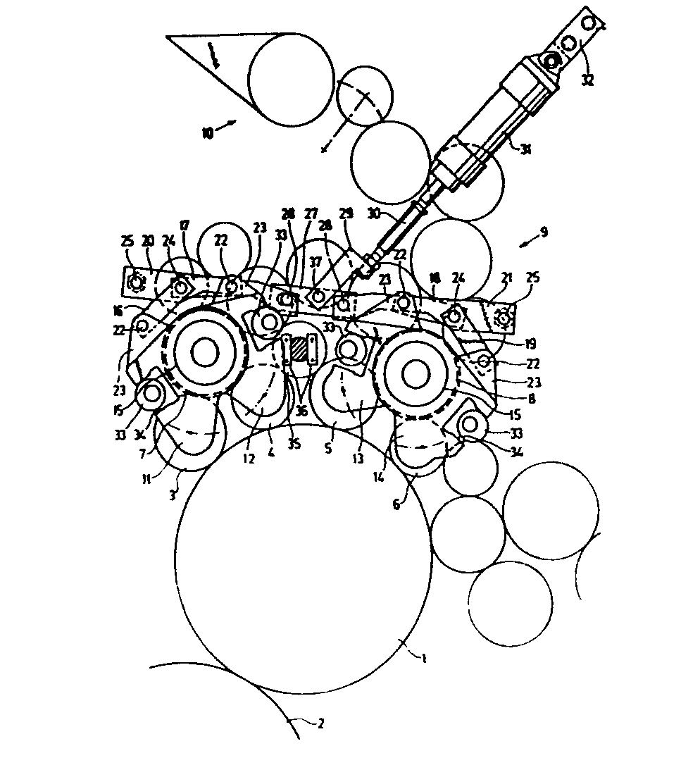
Description
Die Erfindung bezieht sich auf eine Vorrichtung zum An- und Abstellen der Farbauftragwalzen gemäß dem Oberbegriff des Anspruches 1.The invention relates to a device for starting and stopping the inking rollers according to the preamble of
Eine bekannte Ausführung dieser Art (DE-OS 1 949 092) offenbart ein Farbwerk mit drei Farbauftragwalzen, mit einer Lagerung auf Hebeln, die an den Seitengestellen befestigt sind. Den Lagerhebeln sind jeweils Stellhebel zugeordnet, die untereinander in Wirkverbindung stehen. Zum An- und Abstellen der Walzen ist beiderseits auf dem Lager des Plattenzylinders eine Nockenscheibe vorgesehen, auf der eine Rolle, die an einem der Steuerhebel befestigt ist, abrollt. Durch gleichzeitiges Verdrehen der beiden Nockenscheiben auf jeder Maschinenseite können die Farbauftragwalzen an- oder abgestellt werden. Um jedoch eine Anlage der Rolle an der Nockenscheibe bzw. der Steuerhebel aneinander zu gewährleisten, werden mehrere Zugfedern benötigt, die die auf beiden Maschinenseiten vorgesehenen Steuerhebel in Anlage bringen.A known embodiment of this type (DE-OS 1 949 092) discloses an inking unit with three inking rollers, with a bearing on levers which are attached to the side frames. The bearing levers are each assigned actuating levers that are operatively connected to one another. To turn the rollers on and off, a cam disk is provided on both sides on the bearing of the plate cylinder, on which a roller that is attached to one of the control levers rolls. The inking rollers can be turned on or off by simultaneously turning the two cam disks on each side of the machine. However, in order to ensure that the roller abuts against the cam disk or the control lever, several tension springs are required which bring the control lever provided on both machine sides into contact.
Der Nachteil der bekannten Ausführung ist im wesentlichen in der instabilen Lagerung der Farbauftragwalze zu sehen. Rollen diese in ihrer angestellten Position auf der Druckplatte ab, so können z.B. beim Durchgang des Zylinderkanals Schläge entstehen, die zu Schwingungen der Walzen bzw. der Walzenlagerungen führen, so daß beim Aufsetzen der einzelnen Farbauftragwalzen auf die Druckplatte eine Beeinträchtigung der Einfärbung derselben eintreten kann. Insbesondere bei schnellaufenden Maschinen kann dies zu Walzenstreifen führen, die die Herstellung von hochwertigen Druckarbeiten unmöglich machen.The disadvantage of the known design is essentially to be seen in the unstable mounting of the inking roller. If they roll on the pressure plate in their adjusted position, e.g. when passing through the cylinder channel, blows occur which lead to vibrations of the rollers or the roller bearings, so that when the individual inking rollers are placed on the printing plate, the inking can be impaired. In the case of high-speed machines in particular, this can lead to roller strips which make it impossible to produce high-quality printing work.
Ausgehend von diesem Stand der Technik ist es Aufgabe der Erfindung, eine Lagerung und An- und Abstellung der Farbauftragwalzen, insbesondere bei einem Vier-Auftragwalzen-Farbwerk, zu schaffen, die eine gleichmäßige und optimale Einfärbung der Druckform gewährleistet.Based on this prior art, it is an object of the invention to store and turn on and off the color to apply application rollers, especially in a four-application roller inking unit, which ensures a uniform and optimal inking of the printing form.
Die Aufgabe wird mit den kennzeichnenden Merkmalen des Anspruches 1 gelöst. Mit dieser Lösung wird eine schwin- - gungsfreie An- und Abstellung der Farbauftragwalzen erreicht, die ein gleichmäßiges Anstellen derselben bei vorteilhafter Kraftverteilung in den Stellmitteln gewährleistet und auch über eine Fernbedienung betätigbar ist. Die Weiterbildung gemäß Anspruch 2 ermöglicht eine starre Anlage der Lagerhebel der Farbauftragwalzen, insbesondere in der angestellten Stellung, so daß Schwingungen vermieden werden, und eine feinfühlige Einstellung auch während des Maschinenlaufes möglich ist. Mit Anspruch 3 wird das Abstellen der Farbauftragwalzen dahingehend verbessert, daß für weitere an diesen anliegenden Farbwerkswalzen keine separate Steuerung benötigt wird.The object is achieved with the characterizing features of
Ein Ausführungsbeispiel der Erfindung ist in den Zeichnungen schematisch dargestellt.An embodiment of the invention is shown schematically in the drawings.
Es zeigt:
- Fig. 1 eine Seitenansicht eines Farbwerks,
- Fig. 2 einen Teilquerschnitt.
- 1 is a side view of an inking unit,
- Fig. 2 shows a partial cross section.
Das in der Zeichnung wiedergegebene Ausführungsbeispiel bezieht sich auf ein Offsetdruckwerk mit einem Plattenzylinder 1 und einem Gummizylinder 2 in der bekannten Ausführung. Zur Ausführung von hochwertigen Druckarbeiten sind dem Plattenzylinder vier Farbauftragwalzen 3, 4, 5, 6 zugeordnet, die um zwei Reibwalzen 7, 8 schwenkbar gelagert sind. Die Reibwalzen 7, 8 werden von einem nicht dargestellten Farbwerksantrieb mit Maschinengeschwindigkeit angetrieben. In bekannter Weise werden die Reibwalzen 7, 8 über eine Vielzahl Farbwerkswalzen 9 von einer Farbdosiereinrichtung 10 mit einer bestimmten Farbmenge versorgt.The embodiment shown in the drawing relates to an offset printing unit with a
Die Farbauftragwalzen 3-6 sind in Lagerhebeln 11-14 gelagert, die um die Lagerungen 15 der nächstliegenden Reibwalze 7, 8 schwenkbar angeordnet sind. Jeweils zwei Lagerhebel 11, 12 bzw. 13, 14, die an beiden Maschinenseitengestellen vorgesehen sind, werden über Laschen 16-19 mit je einem Steuerhebel 20, 21 verbunden. Die Laschen sind hierbei über Bolzen 22 an Nocken 23 befestigt, die jeweils an den Lagerhebeln 11-14 vorgesehen sind. Auch die Verbindung mit den Steuerhebeln 20, 21 erfolgt über Bolzen 24. Die Steuerhebel 20, 21 selbst sind über Stehbolzen 25 am Maschinenseitengestell 26 befestigt (Figur 2). Zwischen beiden Steuerhebeln 20, 21 ist ein Ausgleichsteg 27 vorgesehen, der über Stehbolzen 28 mit den der Lagerung der Steuerhebel an den Stehbolzen 25 gegenüberliegenden Enden verbunden ist. An diesem Ausgleichsteg 27 greift über einen Gelenkkörper 29 die Kolbenstange 30 eines Stellzylinders 31 an. Dieser wiederum ist über einen Lagerkörper 32 am Maschinenseitengestell 26 abgestützt.The inking rollers 3-6 are mounted in bearing levers 11-14, which are arranged pivotably about the
Durch Betätigen des Stellzylinders 31 wird zum Anstellen der Auftragwalzen 3-6 der Ausgleichsteg 27 nach unten gedrückt, so daß die beiden Steuerhebel 20, 21 kniehebelartig bewegt werden. Hierbei drücken diese über die Bolzen 24 und die Laschen 16-19 die Lagerhebel 11-14 nach unten, so daß die Auftragwalzen 3-6 mit dem Plattenzylinder 1 in Kontakt kommen. Die Anstellbewegung wird hierbei über exzentrische Anschläge 33 begrenzt, an die sich die Ausnehmungen 34 in den Lagerhebeln 11-14 anlegen. Durch Verdrehen der Anschläge 33 über nicht dargestellte Stellspindeln läßt sich- somit die Anstellkraft der Auftragwalzen 3-6 an die Druckplatte des Plattenzylinders 1 feinfühlig einstellen. Bei Beaufschlagung des Stellzylinders 31 in umgekehrter Richtung erfolgt der entgegengesetzte Bewegungsablauf der einzelnen Stellmittel, wobei auch in der abgestellten Position die Lagerhebel 11-14 mit ihren Ausnehmungen 34 an den Anschlägen 33 anliegen.By actuating the actuating
In vorteilhafter Ausgestaltung der Erfindung ist die an den Farbauftragwalzen 4, 5 anliegende Farbwerkswalze 35 über Gleitstücke 36 verschiebbar gelagert, so daß sie der An- und Abstellbewegung der Farbauftragwalzen ohne eigene Stellmittel folgen kann.In an advantageous embodiment of the invention, the inking
Wie aus Figur 2 ersichtlich ist der Gelenkkörper 29 über einen Zapfen 37 mit dem Ausgleichsteg 27 verbunden. Auch ist bei dieser Figur dargestellt, daß die Auftragwalzen 3-6 über Lager 38 in den Lagerhebeln 11 bis 14 vorzugsweise auswechselbar gelagert sind.As can be seen from FIG. 2, the
- 1 Plattenzylinder1 plate cylinder
- 2 Gummizylinder2 rubber cylinders
- 3 Farbauftragwalze3 inking roller
- 4 Farbauftragwalze4 inking roller
- 5 Farbauftragwalze5 inking roller
- 6 Farbauftragwalze6 inking roller
- 7 Reibwalzen7 distribution rollers
- 8 Reibwalzen8 distribution rollers
- 9 Farbwerkswalzen9 inking rollers
- 10 Farbdosiereinrichtung10 color metering device
- 11 Lagerhebel11 bearing lever
- 12 Lagerhebel12 bearing levers
- 13 Lagerhebel13 bearing lever
- 14 Lagerhebel14 bearing lever
- 15 Lagerung15 storage
- 16 Laschen16 tabs
- 17 Laschen17 tabs
- 18 Laschen18 tabs
- 19 Laschen19 tabs
- 20 Steuerhebel20 control levers
- 21 Steuerhebel21 control levers
- 22 Bolzen22 bolts
- 23 Nocken23 cams
- 24 Bolzen24 bolts
- 25 Stehbolzen25 stud bolts
- 26 Maschinenseitengestell26 machine side frame
- 27 Ausgleichssteg27 compensation bridge
- 28 Steckbolzen28 socket pins
- 29 Gelenkkörper29 joint body
- 30 Kolbenstange30 piston rod
- 31 Stellzylinder31 actuating cylinders
- 32 Lagerkörper32 bearing body
- 33 Anschläge33 stops
- 34 Ausnehmungen34 recesses
- 35 Farbwerkswalze35 inking unit roller
- 36 Gleitstücke36 sliders
- 37 Zapfen37 cones
- 38 Lager38 bearings
Claims (3)
daß die Lagerhebel (11-14) auf beiden Maschinenseiten in der angestellten und der abgestellten Stellung an exzentrischen Anschlägen (33) anliegen, die über Stellspindeln einstellbar sind.2. Device according to claim 1, characterized in
that the bearing levers (11-14) rest on both machine sides in the engaged and the disengaged positions on eccentric stops (33) which are adjustable via adjusting spindles.
daß die an den Farbauftragwalzen (3-6) anliegende Farbwerkswalze (35) entgegen der Anstellkraft verschiebbar gelagert ist, so daß sie der An- und Abstellbewegung der Farbauftragwalzen (4,5) ohne eigene Stellmittel folgt.3. Device according to claim 1, characterized in that
that the inking roller (35) resting on the inking rollers (3-6) is displaceably mounted against the setting force, so that it follows the on and off movement of the inking rollers (4, 5) without its own adjusting means.
Applications Claiming Priority (2)
| Application Number | Priority Date | Filing Date | Title |
|---|---|---|---|
| DE3434645A DE3434645C1 (en) | 1984-09-21 | 1984-09-21 | Device for turning the inking rollers on and off in the inking unit of printing machines |
| DE3434645 | 1984-09-21 |
Publications (3)
| Publication Number | Publication Date |
|---|---|
| EP0175237A2 true EP0175237A2 (en) | 1986-03-26 |
| EP0175237A3 EP0175237A3 (en) | 1987-08-19 |
| EP0175237B1 EP0175237B1 (en) | 1989-11-29 |
Family
ID=6245949
Family Applications (1)
| Application Number | Title | Priority Date | Filing Date |
|---|---|---|---|
| EP85111284A Expired EP0175237B1 (en) | 1984-09-21 | 1985-09-06 | Tripping device for inking rollers in printing machines |
Country Status (6)
| Country | Link |
|---|---|
| US (1) | US4711174A (en) |
| EP (1) | EP0175237B1 (en) |
| JP (1) | JPS6178652A (en) |
| AU (1) | AU576611B2 (en) |
| CA (1) | CA1251689A (en) |
| DE (1) | DE3434645C1 (en) |
Families Citing this family (7)
| Publication number | Priority date | Publication date | Assignee | Title |
|---|---|---|---|---|
| DE3434647C2 (en) * | 1984-09-21 | 1986-07-31 | Heidelberger Druckmaschinen Ag, 6900 Heidelberg | Inking unit for rotary printing presses |
| DE3434646C1 (en) * | 1984-09-21 | 1985-11-07 | Heidelberger Druckmaschinen Ag, 6900 Heidelberg | Lifter inking unit of a printing press |
| US5033381A (en) * | 1987-02-06 | 1991-07-23 | Am International, Inc. | Adjustable mounting bracket for printing or duplicating machine roller |
| JP2938491B2 (en) * | 1990-01-10 | 1999-08-23 | 株式会社小森コーポレーション | Printing machine ink unit |
| DE4423286C2 (en) * | 1994-07-02 | 1998-06-04 | Heidelberger Druckmasch Ag | Printing unit for a rotary offset printing machine |
| US6101940A (en) * | 1999-08-13 | 2000-08-15 | Ward Holding Co., Inc. | Printing machine |
| JP3664242B2 (en) * | 2001-03-02 | 2005-06-22 | 株式会社東京機械製作所 | Nip width adjusting device in liquid supply device of printing press |
Family Cites Families (13)
| Publication number | Priority date | Publication date | Assignee | Title |
|---|---|---|---|---|
| CH37358A (en) * | 1906-05-07 | 1907-05-31 | Alfred Maul | Device for holding devices in the set direction on devices which carry adjustable devices |
| DE576179C (en) * | 1927-03-30 | 1933-05-08 | Leslie William Claybourn | Device for turning on and off inking rollers on rotary printing machines |
| US2162812A (en) * | 1937-02-15 | 1939-06-20 | Harris Seybold Potter Co | Inker throw-off |
| BE531592A (en) * | 1953-09-02 | |||
| US2965023A (en) * | 1957-09-18 | 1960-12-20 | Donnelley & Sons Co | Latch and thrust mechanism for printing press ink carriages |
| US3366047A (en) * | 1967-02-23 | 1968-01-30 | Miehle Goss Dexter Inc | Skewing arrangement for plate cylinder and form rollers in printing press |
| US3491686A (en) * | 1967-07-31 | 1970-01-27 | Fred K H Levey Co Inc | Mounting apparatus for ink form rollers |
| US3538849A (en) * | 1968-01-24 | 1970-11-10 | Miehle Goss Dexter Inc | Oscillator ink roller mounting and control means |
| US3595164A (en) * | 1969-04-09 | 1971-07-27 | Wood Industries Inc | Egg carton printer |
| JPS58208055A (en) * | 1982-05-27 | 1983-12-03 | Ryobi Ltd | Perfecting machine |
| DE3221514C2 (en) * | 1982-06-07 | 1986-01-23 | M.A.N.- Roland Druckmaschinen AG, 6050 Offenbach | Dampening system on multicolor rotary printing machines for applying liquids to a plate cylinder |
| US4458591A (en) * | 1982-09-30 | 1984-07-10 | Harris Graphics Corporation | Rotary printing press |
| JPS59142150A (en) * | 1983-02-03 | 1984-08-15 | Komori Printing Mach Co Ltd | Varnish coater for print |
-
1984
- 1984-09-21 DE DE3434645A patent/DE3434645C1/en not_active Expired
-
1985
- 1985-08-06 AU AU45817/85A patent/AU576611B2/en not_active Ceased
- 1985-08-20 CA CA000489022A patent/CA1251689A/en not_active Expired
- 1985-09-06 EP EP85111284A patent/EP0175237B1/en not_active Expired
- 1985-09-20 JP JP60206731A patent/JPS6178652A/en active Granted
- 1985-09-23 US US06/779,234 patent/US4711174A/en not_active Expired - Lifetime
Also Published As
| Publication number | Publication date |
|---|---|
| CA1251689A (en) | 1989-03-28 |
| AU4581785A (en) | 1986-03-27 |
| EP0175237B1 (en) | 1989-11-29 |
| US4711174A (en) | 1987-12-08 |
| DE3434645C1 (en) | 1986-03-13 |
| JPS6178652A (en) | 1986-04-22 |
| JPH0410860B2 (en) | 1992-02-26 |
| AU576611B2 (en) | 1988-09-01 |
| EP0175237A3 (en) | 1987-08-19 |
Similar Documents
| Publication | Publication Date | Title |
|---|---|---|
| EP0425936B1 (en) | Device for quickly registering, fixing and tensioning printing plates | |
| EP0061581A1 (en) | Support for rollers that can be applied to the plate cylinder of an offset or letterpress printing machine | |
| DE3207622A1 (en) | DEVICE FOR TURNING ON, OFF AND ADJUSTING APPLICATION ROLLERS ON THE PLATE CYLINDER OF PRINTING MACHINES | |
| DE1611251B1 (en) | ADJUSTMENT DEVICE FOR THE INK AND WATER APPLICATION ROLLERS AGAINST AN INCLINED FORMING CYLINDER OF ROTARY PRINTING MACHINES | |
| DE2703345C3 (en) | Friction drive for at least two friction rollers | |
| DE19730681A1 (en) | Setting device to set rolls against printing form cylinder surface | |
| DD210535A3 (en) | DEVICE FOR ADJUSTING COLOR OR MOISTURE ROLLING ROLLERS | |
| EP0826501B2 (en) | Device for adjusting an inking or damping roller in a printing machine | |
| DE2627963C2 (en) | Device on printing machines for adjusting the inking rollers that can be brought into contact with the plate cylinder | |
| EP0512267B1 (en) | Laminator | |
| EP0845352A1 (en) | Device for adjusting printing cylinders in a printing unit of a rotary printing machine | |
| EP0175237B1 (en) | Tripping device for inking rollers in printing machines | |
| EP0154843A2 (en) | Tensioning device for printing plates | |
| DE4400563C2 (en) | Roller in an inking unit or dampening unit of a rotary printing press | |
| EP0741024B1 (en) | Device for bringing rollers in and out of contact | |
| DE10132156B4 (en) | Web stabilization for non-contact web guidance on flying changeable printing units | |
| EP0425935B1 (en) | Device for the parallel tensioning of printing plates | |
| DE3434647C2 (en) | Inking unit for rotary printing presses | |
| EP0741018B1 (en) | Device for bearing an applicator roll | |
| DE19753820A1 (en) | Device for the mutual adjustment of printing unit cylinders | |
| DE2725725A1 (en) | FLAT OFFSET PRESS | |
| DE9104151U1 (en) | Device for adjusting the center distance between the blanket cylinder and the impression cylinder of a sheet-fed offset printing machine | |
| DE4134310C2 (en) | Device for quick clamping of printing plates | |
| DE19711692C2 (en) | Device for aligning plate cylinders | |
| DE102006050567B4 (en) | printing unit |
Legal Events
| Date | Code | Title | Description |
|---|---|---|---|
| PUAI | Public reference made under article 153(3) epc to a published international application that has entered the european phase |
Free format text: ORIGINAL CODE: 0009012 |
|
| 17P | Request for examination filed |
Effective date: 19850906 |
|
| AK | Designated contracting states |
Kind code of ref document: A2 Designated state(s): CH FR GB IT LI NL SE |
|
| PUAL | Search report despatched |
Free format text: ORIGINAL CODE: 0009013 |
|
| AK | Designated contracting states |
Kind code of ref document: A3 Designated state(s): CH FR GB IT LI NL SE |
|
| 17Q | First examination report despatched |
Effective date: 19881011 |
|
| GRAA | (expected) grant |
Free format text: ORIGINAL CODE: 0009210 |
|
| AK | Designated contracting states |
Kind code of ref document: B1 Designated state(s): CH FR GB IT LI NL SE |
|
| ITF | It: translation for a ep patent filed | ||
| ET | Fr: translation filed | ||
| GBT | Gb: translation of ep patent filed (gb section 77(6)(a)/1977) | ||
| PLBE | No opposition filed within time limit |
Free format text: ORIGINAL CODE: 0009261 |
|
| PLBE | No opposition filed within time limit |
Free format text: ORIGINAL CODE: 0009261 |
|
| STAA | Information on the status of an ep patent application or granted ep patent |
Free format text: STATUS: NO OPPOSITION FILED WITHIN TIME LIMIT |
|
| 26N | No opposition filed | ||
| 26N | No opposition filed | ||
| ITTA | It: last paid annual fee | ||
| PGFP | Annual fee paid to national office [announced via postgrant information from national office to epo] |
Ref country code: SE Payment date: 19920911 Year of fee payment: 8 |
|
| PGFP | Annual fee paid to national office [announced via postgrant information from national office to epo] |
Ref country code: NL Payment date: 19920930 Year of fee payment: 8 |
|
| PG25 | Lapsed in a contracting state [announced via postgrant information from national office to epo] |
Ref country code: SE Effective date: 19930907 |
|
| PG25 | Lapsed in a contracting state [announced via postgrant information from national office to epo] |
Ref country code: NL Effective date: 19940401 |
|
| NLV4 | Nl: lapsed or anulled due to non-payment of the annual fee | ||
| EUG | Se: european patent has lapsed |
Ref document number: 85111284.7 Effective date: 19940410 |
|
| PGFP | Annual fee paid to national office [announced via postgrant information from national office to epo] |
Ref country code: GB Payment date: 19990817 Year of fee payment: 15 |
|
| PGFP | Annual fee paid to national office [announced via postgrant information from national office to epo] |
Ref country code: FR Payment date: 19990917 Year of fee payment: 15 |
|
| PGFP | Annual fee paid to national office [announced via postgrant information from national office to epo] |
Ref country code: CH Payment date: 19990930 Year of fee payment: 15 |
|
| PG25 | Lapsed in a contracting state [announced via postgrant information from national office to epo] |
Ref country code: GB Free format text: LAPSE BECAUSE OF NON-PAYMENT OF DUE FEES Effective date: 20000906 |
|
| PG25 | Lapsed in a contracting state [announced via postgrant information from national office to epo] |
Ref country code: LI Free format text: LAPSE BECAUSE OF NON-PAYMENT OF DUE FEES Effective date: 20000930 Ref country code: CH Free format text: LAPSE BECAUSE OF NON-PAYMENT OF DUE FEES Effective date: 20000930 |
|
| GBPC | Gb: european patent ceased through non-payment of renewal fee |
Effective date: 20000906 |
|
| REG | Reference to a national code |
Ref country code: CH Ref legal event code: PL |
|
| PG25 | Lapsed in a contracting state [announced via postgrant information from national office to epo] |
Ref country code: FR Free format text: LAPSE BECAUSE OF NON-PAYMENT OF DUE FEES Effective date: 20010531 |
|
| REG | Reference to a national code |
Ref country code: FR Ref legal event code: ST |