EP0174196A2 - Material für in Kathodenstrahlröhren eingebaute Komponenten und sein Herstellungsverfahren - Google Patents
Material für in Kathodenstrahlröhren eingebaute Komponenten und sein Herstellungsverfahren Download PDFInfo
- Publication number
- EP0174196A2 EP0174196A2 EP85306308A EP85306308A EP0174196A2 EP 0174196 A2 EP0174196 A2 EP 0174196A2 EP 85306308 A EP85306308 A EP 85306308A EP 85306308 A EP85306308 A EP 85306308A EP 0174196 A2 EP0174196 A2 EP 0174196A2
- Authority
- EP
- European Patent Office
- Prior art keywords
- alloy
- tube
- rolling
- annealing
- shadow mask
- Prior art date
- Legal status (The legal status is an assumption and is not a legal conclusion. Google has not performed a legal analysis and makes no representation as to the accuracy of the status listed.)
- Granted
Links
Images
Classifications
-
- H—ELECTRICITY
- H01—ELECTRIC ELEMENTS
- H01J—ELECTRIC DISCHARGE TUBES OR DISCHARGE LAMPS
- H01J29/00—Details of cathode-ray tubes or of electron-beam tubes of the types covered by group H01J31/00
- H01J29/02—Electrodes; Screens; Mounting, supporting, spacing or insulating thereof
-
- C—CHEMISTRY; METALLURGY
- C22—METALLURGY; FERROUS OR NON-FERROUS ALLOYS; TREATMENT OF ALLOYS OR NON-FERROUS METALS
- C22C—ALLOYS
- C22C38/00—Ferrous alloys, e.g. steel alloys
- C22C38/18—Ferrous alloys, e.g. steel alloys containing chromium
- C22C38/40—Ferrous alloys, e.g. steel alloys containing chromium with nickel
- C22C38/52—Ferrous alloys, e.g. steel alloys containing chromium with nickel with cobalt
-
- H—ELECTRICITY
- H01—ELECTRIC ELEMENTS
- H01J—ELECTRIC DISCHARGE TUBES OR DISCHARGE LAMPS
- H01J29/00—Details of cathode-ray tubes or of electron-beam tubes of the types covered by group H01J31/00
- H01J29/02—Electrodes; Screens; Mounting, supporting, spacing or insulating thereof
- H01J29/06—Screens for shielding; Masks interposed in the electron stream
- H01J29/07—Shadow masks for colour television tubes
-
- H—ELECTRICITY
- H01—ELECTRIC ELEMENTS
- H01J—ELECTRIC DISCHARGE TUBES OR DISCHARGE LAMPS
- H01J2229/00—Details of cathode ray tubes or electron beam tubes
- H01J2229/07—Shadow masks
- H01J2229/0727—Aperture plate
- H01J2229/0733—Aperture plate characterised by the material
Definitions
- This invention relates to a material for in-tube components and a method of manufacture thereof, capable of use in manufacturing with good formability in-tube components such as shadow masks, frames, inner shields and bimetallic elements used in electronic tubes such as colour cathode ray tubes.
- in-tube components of colour cathode ray tubes such as shadow masks, frames, inner shields and bimetallic elements
- materials such as rimmed steel or Al killed steel, which have good etching characteristics and formability and a surface on which it is easy to form an oxide film that contributes to lessening the reflection of the electron beam.
- rimmed steel or Al killed steel which have good etching characteristics and formability and a surface on which it is easy to form an oxide film that contributes to lessening the reflection of the electron beam.
- drawbacks have appeared in the use of rimmed steel or Al killed steel as referred to above for shadow masks, frames, inner shields and bimetallic elements.
- the temperature of the aforementioned members rises to 30 to 100 °C, causing for example what is called “doming", due to strain in the formed shape of the shadow mask produced by its thermal expansion.
- PD purity drift
- the apertures, and the aperture pitch, of the aforementioned shadow mask are very small, so that the proportion of relative misalignment becomes large, preventing the use of in-tube components made of the aforementioned rimmed steel or Al killed steel.
- the above problem is particularly marked in the case of colour cathode ray tubes of high curvature with reduced image distortion and reflection of external light.
- Ni-Fe alloys of small thermal expansion coefficient such as invar (36Ni-Fe) or super-invar (32Ni-5Co-Fe) have been used as the material for forming in-tube components of this type, for example as proposed in U.S. Patent No. 4,420,366 (Oka et al), Japanese Publication No. Sho. 42-25446, Japanese Patent Laid-Open No. Sho 50-58977, or Japanese Patent Laid-Open No. Sho. 50-68650.
- Ni-Fe alloys of this type have poor thermal conductivity. Not only does this make them liable to accumulate heat, but also makes them liable to what is known as “spring-back” (depressions towards the electron gun, from the normal spherical surface of the shadow mask).
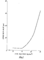
- this spring-back exhibits the correlation shown in Figure 1 with for example the 0.2% yield point of the material.
- the lower the 0.2% yield point the smaller the amount of spring-back and the better the formability.
- the present invention seeks to provide a material suitable for use in in-tube components whose thermal expansion coefficient is lower than that of rimmed steel or Al killed steel and which has good etching characteristics and formability, close to those possessed by the aforementioned steels, and also seeks to provide a method of manufacturing this material.
- This invention provides a material suitable for in-tube components whose main constituent is an Fe-Ni alloy, of which the main constituent is Fe and containing 25 - 45 wt% Ni, 0.3 - 10 wt% Cr (which may be partially replaced by Mn), 0 - 10 wt% Co, together with unavoidable impurities.
- Another aspect of this invention comprises using an alloy of grain size set at 2,000 - 40,000 grains/mm 2 (i.e. grain size 8 - 12 as defined in Japanese Industrial Standard JIS-G0551), and formed to be of at least 80% austenitic structure as the material for forming in-tube components such as the shadow mask, inner shield, frame, and bimetallic element in a colour cathode ray tube.
- an alloy of grain size set at 2,000 - 40,000 grains/mm 2 i.e. grain size 8 - 12 as defined in Japanese Industrial Standard JIS-G0551
- in-tube components such as the shadow mask, inner shield, frame, and bimetallic element in a colour cathode ray tube.
- Such an in-tube component material may be manufactured by melting an alloy containing 25-45 wt% Ni, 0.3 - 10 wt% Cr (which may be partially replaced by Mn), 0 - 10 wt% Co, the remainder Fe and unavoidable impurities, subjecting it to rolling and annealing, then carrying out final cold rolling with a draft of at least 40%, preferably at least 70%, then performing annealing treatment in a temperature range of 500 - 1200 °C, preferably 900 - 1100°C, then performing controlled rolling with a draft of less than 30%, preferably less than 20%, and, if necessary, carrying out strain-relief annealing to obtain an in-tube component material of grain size 2,000 - 40,000 grains/mm 2 .
- Ni content is made 25 - 45 wt% is to make the thermal expansion coefficient less than 90 x 10 -7 /°C. If the added amount of Ni is outside this range, an in-tube component material of low thermal expansion coefficient as sought by this invention is not obtained. This means that a well-defined image with low PD is not obtained. On the other hand, if the added amount of Ni exceeds 45 wt%, the 0.2% yield point, which is the criterion of formability, is increased, and the formability is very adversely affected. In the case of a shadow mask for example, this leads to spring-back, making it hard to produce a well-defined image. Resistance to oxidation is aleo increased, making it extremely difficult to subject the surface of the component to the usual blackening treatment.
- etching characteristics if the Ni content is made large, fine etching becomes difficult, with problems such as loss of etching speed due to so-called "rough pits" being formed in the inside walls of the etching holes and a large amount of Ni being dissolved into the etching solution.
- Co has the effect of decreasing the thermal expansion coefficient and improving etching characteristics.
- the lower - limit of the Co content if it is to have any effect in lowering the thermal expansion coefficient is 0.2 wt%. It is, however, possible to make the Co content zero.
- the reason for the choice of the upper limit of 10 wt% is that the 0.2% yield point increases little by little with increased Co addition, and the thermal expansion coefficient also increases.
- the added amount of Co is therefore preferably 3 - 6 wt%.
- Cr increases the thermal expansion coefficient of Fe-Ni alloys, but, on the other hand, it makes a large contribution to improving formability, by reducing the aforementioned 0.2% yield point. That is, the aforementioned Cr plays an important role in the annealing step after the flat mask with multiple holes has been obtained by etching in-tube component material of grain size 2,000 - 40,000 grains/mm .
- the amount of decrease of the 0.2% yield point is very much greater than in a 36Ni-Fe alloy or 32Ni-5Co-Fe alloy to which Cr has not been added. That is, the Cr contained in the material has an important effect in considerably decreasing the 0.2% yield point of the material in the annealing stage.
- the amount of Cr added is less than 0.3 wt%, even if the annealing temperature is made as high as 1200 o C, as with 32Ni-5Co-Fe alloy containing no Cr, its 0.2% yield point cannot be reduced below 24 kg/mm 2 ( 20 kg/mm 2 in the case of 36Ni-Fe alloy). And if the added amount of Cr exceeds 10 wt%, the thermal expansion coefficient becomes 90 X 10 / C or more, causing purity drift. Such an alloy would therefore be unsuitable for use in high precision colour cathode ray tubes. Also if the added amount of Cr exceeds 10 wt%, a protective film of Cr 2 O 3 tends to be formed on the surface of the alloy. This is inconvenient in blackening treatment, since it lowers the rate of blackening. Taking into account lowered expansion, etching characteristics, and low chroming in waste liquid, the amount of Cr should preferably be 1 - 4 wt%.
- the material of the comparative example on annealing at 1150°C, a spring- back value of more than 100 micron is found. This therefore imposes limitations on warm pressing or on the shadow mask shapes that can be used.
- the material of this invention has a yield point of 16 kg/mm 2 , and its spring-back value is 5 micron or less. Good molding quality can therefore be maintained.
- Another element which has the same effect as Cr when added is Mn. Some of the aforementioned Cr can therefore be replaced by addition of Mn.
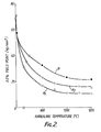
- the characteristic Al shows the variation of the 0.2% yield point with annealing temperature of a material according to this invention consisting of a 36Ni-Fe alloy to which 6 wt% of Cr has been added.
- the characteristic A2 shows the variation of the 0.2% yield point with annealing temperature of a material according to this invention consisting of a 36Ni-Fe alloy to which 3 wt% of Cr has been added.
- the characteristic B shows for purposes of comparison the variation of the 0.2% yield point with annealing temperature of a material consisting of a 36Ni-Fe alloy to which no Cr has been added.
- the 0.2% yield point of the in-tube component material according to this invention is higher, but on annealing at/ 500°C or more a much lower 0.2% yield point is obtained than with the prior art material.
- the 0.2% yield point of in-tube component material according to this invention when vacuum-annealed at 10 00 C - 1200°C is 12 kg/mm 2
- the 0.2% yield point of the prior art alloy, without Cr addition is as large as about 22 kg/mm 2 . It can therefore be seen, from this faci also, that the aforementioned Cr addition contributes greatly to lowering of the 0.2% yield point on annealing.
- Mn also has the same effect as Cr. Some of the Cr can therefore be replaced by Mn.
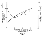
- Fig. 3 shows the variation characteristic C of the 0.2% yield point on annealing a flat mask formed using the in-tube component material of this invention at 900°C in hydrogen, and the variation characteristic D of its thermal expansion coefficient. From this Figure also, it can be seen that, if the Cr content is made 0.3 - 10 wt%, the 0.2% yield point can be kept below 20 kg/mm 2 or less by annealing.
- in-tube component material of this type it is vital to have excellent etching characteristics.
- uniformity of sheet thickness and uniformity of distribution of the constituents can be achieved by advances in rolling techinques, while inclusions can be eliminated by reducing the amount of unavoidable impurities to an absolute minimum.
- the problem in obtaining in-tube component material of good etching characteristics therefore lies in obtaining uniformity of grain size and of metallic structure.
- an alloy containing 25 (which may-be partially replaced by Mn). - 45 wt% Ni, 0.3 - 10 wt% Cr/ 0 - 10 wt% Co, the remainder Fe and unavoidable impurities, is melted, subjected to is rolling and annealing, then final cold rolling / performed with a draft of at least 40%, preferably at least 70%, then subjected to annealing treatment in a temperature range of 500 - 1200°C, preferably 900 - 1100°C, then to controlled rolling of draft not more than 30%,preferably not more than 20%, and if necessary to strain-relief annealing to obtain a material of grain size 8 - 12, i.e.
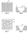
- the grain size must be set to 8 - 12 (2,000 - 40,000 grains/mm 2 ), so as to make it possible to form uniform holes, as shown in Fig. 5.
- the aforesaid grain size is set to at least 9 - 11.
- the aforementioned cold rolling is performed with a draft of less than 40%, it becomes difficult a to get the metallic structure even, and sometimes/grain size of 2,000 - 40,000 grains/mm will not be obtained. And if the aforementioned annealing is performed below 500°C, the grain size cannot be controlled. On the other hand, if annealing is performed at more than 1200 o C, the diameter of the grains may become too large. That is, to assure good etching characteristrics, the temperature range of the aforementioned annealing should be set as specified above. The in-tube component material must therefore be manufactured under the aforementioned conditions.
- the alloy should be of only a single type of metallic structure.
- the aforementioned austenitic structure represents at least 80% of the total.
- the excellent shape characteristics shown iri Fig. 5 can be effectively obtained by etching treatment to give well-defined holes.
- this controlled rolling it should be noted that if the draft is made larger than 30% the metal texture may be destroyed, which is undesirable.
- This invention is therefore very effective in providing a material for the manufacture of shadow maks etc., because, according to this invention, by adding Cr to a prescribed Ni-Fe alloy, its 0.2% yield pointe is reduced and its formability is improved, and by controlling the grain size and metallic structure, the etching characteristic are improved. Moreover, vacuum annealing at high temperature, such as was required with the prior art 32Ni-5Co-Fe alloy, becomes unnecessary and the time required for processes such as warm pressing is eliminated, and by annealing at 1200°C or less, sufficient forming working can be achieved and the etching treatment time can be shortened, enabling uniformly etched holes to be produced.
- the thermal expansion coefficient can also be made less than that of the prior art Al killed steel or rimmed steel, and is in fact less than 90 x 10 -7 /°C. This has the effect that colour cathode ray tubes with little purity drift can easily be realised.
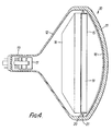
- FIG.4 shows an embodiment wherein the invention is applied to a colour cathode ray tube.
- a phosphor screen 14, shadow mask assembly 15, inner shield 16 and electron gun 17 are arranged within a glass encosure 10 formed with a panel 11, funnel 12 and neck 13.
- the shadow mask assembly 15 comprises a shadow mask 18 that is formed into a curved surface, and a mask frame 19 that supports the peniphery of this mask 18. This is fixed, by means of spring support 20 welded to the frame 19, to a stud pin 21 anchored in the inner wall of the panel.
- the shadow mask assembly 15, inner shield 16, electron gun 17, spring support 20 and stud pin 21 etc. constitute the in-tube components of the colour cathode ray tube.
- the invention was applied to the inner shield 16 and shadow mask 18, which are formed of the material and by the manufacturing method detailed below.
- an ingot of alloy containing 32% Ni, 5% Co and Fe as the main constituent, with 4 wt% Cr, and 0.005 wt% C, 0.01 wt% Si, and 0.001 wt% of each of P and S respectively was prepared by vacuum melting. This ingot was then subjected to repeated annealing, washed with acid, and the primary and secondary cold rolling steps performed. A draft of 80% was used in this process.
- this material was annealed at 10-4 torr, 800°C in a box-type annealing furnace, then subjected to controlled rolling with a draft of 10%.
- controlled rolling an in-tube component material having an austenitic structure and of grain size 10 ( 8 ,200 grains/mm 2 on average) as defined in JIS-G0551 was obtained.
- a shadow mask was produced as follows using the in-tube component material manufactured as above.
- both faces of the material were coated with a photoresist, which was .dried.
- a film formed with a standard pattern in the shape of slots or round dots was then stuck tightly onto both faces, and the photoresist exposed and developed.
- the unexposed portions of photoresist were removed by dissolving in this development process.
- the remaining photoresist was hardened by burning then etched with ferric chloride solution.
- the remaining resist was then removed with hot alkali to obtain a flat mask, to be used to form the shadow mask.
- This flat mask was treated for strain-relief and improvement of working properties by placing it in a box-type vacuum heating furnace, where it was annealed in an atmosphere of 10-4 torr, 1000°C. Sheet strain was then removed by passing the annealed flat mask through a leveller, simultaneously removing stretcher strain in the forming step. This vacuum annealing was performed with the object of decreasing the amount of dissolved C in the flat mask and reducing the 0.2% yield point by increasing the grain diameter, in order to facilitate subsequent press forming.
- the aforementioned flat mask was press formed, to obtain a shadow mask having the prescribed curvature.
- the material had a low 0.2% yield point with excellent formability, so that spring-back did not occur.
- the material characteristics were uniform in the width direction and longitudinal direction of the shadow mask, preventing the adverse effect on formability caused by what is known as statistical scatter of these characteristics.
- the round electron beam holes 22 that were formed in the shadow mask 18 by the mask etching are all regularly arranged, and irregular holes 23 as shown in Fig. 7 for purposes of comparison were not produced.
- the inclined faces 24 of the holes 22 were smoothly etched, and the rough holes (holes having a rough surface) 25 as shown for comparison in Fig. 8 were not produced.
- the shadow mask was washed in trichloroethylene vapour, and heated for 20 minutes in a continuous blackening furnace maintained at 700 C to complete the shadow mask 18 by growing a tightly adhering 1.5 micron thick blackening film.
- the colour cathode ray tube was then completed by applying red, blue and green phosphors in correspondence with the holes of the shadow mask, Al evaporation, and Dag application, followed by attachment of the inner shield 16, and connection of this panel 11 to the funnel 12 at the rear of the envelope, on which is mounted the electron gun 17, and evacuation of the interior.
- the same material as that described above is also used for the aforementioned inner shield.
- Respective ingots were prepared of alloys containing 32% Ni, 5% Co and Fe as the main constituent, and 3 wt% Cr, and, as incidental constituents, 0.05 wt% of C, 0.02 wt% of Si, and 0.001 wt% of P and S .respectively. Shadow masks were then made using the ingots of the alloy, in the same way as in Embodiment 1, and these were used to manufacture colour cathode ray tubes.
- an ingot of alloy containing 36% Ni, and Fe as the main constituent, with 6 wt% Cr, and 0.005 wt% C, 0.01 wt% Si, and 0.001 wt% Of each of P and S respectively was prepared by vacuum melting. This ingot was then subjected to repeated hot rolling, washed with acid, and the primary and secondary cold rolling steps performed. A draft of 80% was used in this process.
- this material was annealed at 10 -4 torr, 800°C in a box-type annealing furnace, then subjected to controlled rolling with a draft of 10%.
- controlled rolling an in-tube component material having an austenitic structure and of grain size 10 ( 8 , 20 0 grains/mm 2 on average) as defined in JIS-G0551 was obtained.
- a shadow mask was produced using the in-tube component material manufactured as above, by the method of Example 1. It was found that this shadow mask material had a small 0.2% yield point and excellent formability, and did not give rise to spring-back. It was also confirmed that the material characteristics were uniform in the width direction and longitudinal direction of the shadow mask, preventing the adverse effect on formability caused by what is known as statistical scatter of these characteristics.
- Example 1 The following Table shows the etching characteristics and formability of in-tube component material (samples (1) and (2)) according to this invention adjusted to grain size 2,000 - 40,000 grains/mm 2 .
- This material was a 36Ni-4Cr-Fe alloy produced by including a 4% Cr content in an iron alloy of 36% Ni content.
- Sample (3) is given for purposes of comparison.
- This sample was a 36Ni-4Cr-Fe alloy whose grain size was not adjusted.
- Sample (4) is also given for purposes of comparison and is a sample which had a fine grain size produced by rolling. In both cases, the etching characteristics were poor. Also in the case of sample (4), it was found that some mask strain was produced, causing camber.
- the heading "Metallic structure” indicates the proportion of austenitic structure as determined by X-ray diffraction.
- the evaluation of "Etching characteristics” was made on the following basis: good etching characteristics - holes formed through the mask in over 99% of cases, the holes not having rough walls; rather poor etching characteristics - although holes were formed through the mask in over 99% of cases, the holes were "rough holes”.
- the criterion of good formability was that spring-back was less than 20 micron on forming after annealing the etched flat plate at 1100°C in vacuum.
- the effectiveness of this invention is considerable in that with in-tube component material according to this invention both good etching characteristics and good formability can be obtained.
- the same effect is obtained by adding Cr to an alloy consisting of 25 - 35 wt% Ni, and 0.2 - 10 wt%, preferably 3 - 6 wt%, of Co, and the remainder Fe.
- a material whose thermal coefficient of expansion has been further reduced by Co addition has a 0.2% yield point about 2 - 5 kg/mm 2 2 higher than when no Co is added, and so has poorer formability.
- a material according to this invention is therefore very useful in that the Cr addition gives a lower 0.2% yield point without increasing the thermal expansion coefficient.
Landscapes
- Chemical & Material Sciences (AREA)
- Engineering & Computer Science (AREA)
- Materials Engineering (AREA)
- Mechanical Engineering (AREA)
- Metallurgy (AREA)
- Organic Chemistry (AREA)
- Electrodes For Cathode-Ray Tubes (AREA)
- Heat Treatment Of Steel (AREA)
- Heat Treatment Of Sheet Steel (AREA)
Applications Claiming Priority (4)
| Application Number | Priority Date | Filing Date | Title |
|---|---|---|---|
| JP186874/84 | 1984-09-06 | ||
| JP59186874A JPS6164853A (ja) | 1984-09-06 | 1984-09-06 | 管内部品用素材とその製造方法 |
| JP25691/85 | 1985-02-13 | ||
| JP60025691A JPH0676645B2 (ja) | 1985-02-13 | 1985-02-13 | 管内部品用素材とその製造方法 |
Publications (3)
| Publication Number | Publication Date |
|---|---|
| EP0174196A2 true EP0174196A2 (de) | 1986-03-12 |
| EP0174196A3 EP0174196A3 (en) | 1986-08-06 |
| EP0174196B1 EP0174196B1 (de) | 1989-03-22 |
Family
ID=26363350
Family Applications (1)
| Application Number | Title | Priority Date | Filing Date |
|---|---|---|---|
| EP85306308A Expired EP0174196B1 (de) | 1984-09-06 | 1985-09-05 | Material für in Kathodenstrahlröhren eingebaute Komponenten und sein Herstellungsverfahren |
Country Status (2)
| Country | Link |
|---|---|
| EP (1) | EP0174196B1 (de) |
| DE (1) | DE3569061D1 (de) |
Cited By (15)
| Publication number | Priority date | Publication date | Assignee | Title |
|---|---|---|---|---|
| EP0175370A2 (de) * | 1984-09-21 | 1986-03-26 | Kabushiki Kaisha Toshiba | Bildröhre |
| EP0251821A2 (de) * | 1986-07-04 | 1988-01-07 | Kabushiki Kaisha Toshiba | Schattenmaske und deren Herstellungsverfahren |
| EP0405226A2 (de) * | 1989-06-13 | 1991-01-02 | Kabushiki Kaisha Toshiba | Nichtmagnetischer rostfreier Stahl |
| EP0534460A1 (de) * | 1991-09-27 | 1993-03-31 | Yamaha Metanix Corporation | Eisen-Nickel-Kobalt Legierung für Lochmasken |
| EP0561120A1 (de) * | 1992-01-24 | 1993-09-22 | Nkk Corporation | Dünnes Blech aus Fe-Ni-Legierung für Schattenmaske und Verfahren zu dessen Herstellung |
| US5453138A (en) * | 1992-02-28 | 1995-09-26 | Nkk Corporation | Alloy sheet |
| US5456771A (en) * | 1992-01-24 | 1995-10-10 | Nkk Corporation | Thin Fe-Ni alloy sheet for shadow mask |
| US5562783A (en) * | 1992-01-24 | 1996-10-08 | Nkk Corporation | Alloy sheet for shadow mask |
| FR2733767A1 (fr) * | 1995-05-05 | 1996-11-08 | Imphy Sa | Alliage fe-co-ni et utilisation pour la fabrication d'un masque d'ombre |
| US5620535A (en) * | 1992-01-24 | 1997-04-15 | Nkk Corporation | Alloy sheet for shadow mask |
| EP0803584A2 (de) * | 1990-06-29 | 1997-10-29 | Kabushiki Kaisha Toshiba | Legierung auf Fe-Ni Basis |
| GB2336939A (en) * | 1998-04-30 | 1999-11-03 | Dainippon Printing Co Ltd | Shadow mask for a color picture tube |
| GB2336940A (en) * | 1998-04-30 | 1999-11-03 | Dainippon Printing Co Ltd | Shadow mask for a color picture tube |
| US6806635B1 (en) | 1999-09-29 | 2004-10-19 | Nippon Mining And Metals Co., Ltd. | Fe-Ni-Cr- based alloy strip having improved press-formability and used for electrode of electron gun |
| EP2312622B1 (de) * | 2009-10-15 | 2019-10-23 | Mitsubishi Electric Corporation | Leistungshalbleitervorrichtung mit einem Substrat mittels eines Sn-Sb-Cu-Lotes verbundenen Leistungshalbleiterbauelement und mit einem mit dem Substrat mittels eines Sn-Ag-basierten oder Sn-Ag-Cu-basierten Lotes verbundenen Anschlusselement und Herstellungsverfahren dafür |
Citations (3)
| Publication number | Priority date | Publication date | Assignee | Title |
|---|---|---|---|---|
| FR2231101A1 (en) * | 1973-05-23 | 1974-12-20 | Metallgesellschaft Ag | Iron-nickel alloys - use as shadow masks for colour television |
| US4420366A (en) * | 1982-03-29 | 1983-12-13 | Tokyo Shibaura Denki Kabushiki Kaisha | Method for manufacturing shadow mask |
| JPS5959861A (ja) * | 1982-09-29 | 1984-04-05 | Toshiba Corp | 管内部品 |
-
1985
- 1985-09-05 EP EP85306308A patent/EP0174196B1/de not_active Expired
- 1985-09-05 DE DE8585306308T patent/DE3569061D1/de not_active Expired
Patent Citations (3)
| Publication number | Priority date | Publication date | Assignee | Title |
|---|---|---|---|---|
| FR2231101A1 (en) * | 1973-05-23 | 1974-12-20 | Metallgesellschaft Ag | Iron-nickel alloys - use as shadow masks for colour television |
| US4420366A (en) * | 1982-03-29 | 1983-12-13 | Tokyo Shibaura Denki Kabushiki Kaisha | Method for manufacturing shadow mask |
| JPS5959861A (ja) * | 1982-09-29 | 1984-04-05 | Toshiba Corp | 管内部品 |
Non-Patent Citations (1)
| Title |
|---|
| PATENTS ABSTRACTS OF JAPAN, vol. 8, no. 156 (C-234)[1593], 19th July 1984; & JP-A-59 059 861 (TOSHIBA K.K.) 05-04-1984 * |
Cited By (31)
| Publication number | Priority date | Publication date | Assignee | Title |
|---|---|---|---|---|
| EP0175370B1 (de) * | 1984-09-21 | 1990-12-12 | Kabushiki Kaisha Toshiba | Bildröhre |
| EP0175370A2 (de) * | 1984-09-21 | 1986-03-26 | Kabushiki Kaisha Toshiba | Bildröhre |
| EP0251821A2 (de) * | 1986-07-04 | 1988-01-07 | Kabushiki Kaisha Toshiba | Schattenmaske und deren Herstellungsverfahren |
| EP0251821A3 (de) * | 1986-07-04 | 1990-04-18 | Kabushiki Kaisha Toshiba | Schattenmaske und deren Herstellungsverfahren |
| EP0405226A2 (de) * | 1989-06-13 | 1991-01-02 | Kabushiki Kaisha Toshiba | Nichtmagnetischer rostfreier Stahl |
| EP0405226A3 (en) * | 1989-06-13 | 1991-12-04 | Kabushiki Kaisha Toshiba | Non-magnetic stainless steel |
| EP0803584A2 (de) * | 1990-06-29 | 1997-10-29 | Kabushiki Kaisha Toshiba | Legierung auf Fe-Ni Basis |
| EP0803584A3 (de) * | 1990-06-29 | 1997-12-29 | Kabushiki Kaisha Toshiba | Legierung auf Fe-Ni Basis |
| EP0534460A1 (de) * | 1991-09-27 | 1993-03-31 | Yamaha Metanix Corporation | Eisen-Nickel-Kobalt Legierung für Lochmasken |
| EP0561120A1 (de) * | 1992-01-24 | 1993-09-22 | Nkk Corporation | Dünnes Blech aus Fe-Ni-Legierung für Schattenmaske und Verfahren zu dessen Herstellung |
| US5456771A (en) * | 1992-01-24 | 1995-10-10 | Nkk Corporation | Thin Fe-Ni alloy sheet for shadow mask |
| US5503693A (en) * | 1992-01-24 | 1996-04-02 | Nkk Corporation | Method for producing a thin Fe-Ni alloy for shadow mask |
| US5520755A (en) * | 1992-01-24 | 1996-05-28 | Nkk Corporation | Method for manufacturing thin Fe--Ni alloy sheet for shadow mask |
| US5562783A (en) * | 1992-01-24 | 1996-10-08 | Nkk Corporation | Alloy sheet for shadow mask |
| US5501749A (en) * | 1992-01-24 | 1996-03-26 | Nkk Corporation | Method for producing a thin Fe-Ni alloy for shadow mask thereof |
| US5605581A (en) * | 1992-01-24 | 1997-02-25 | Nkk Corporation | Thin Fe-Ni alloy sheet for shadow mask and method for manufacturing thereof |
| US5620535A (en) * | 1992-01-24 | 1997-04-15 | Nkk Corporation | Alloy sheet for shadow mask |
| US5628841A (en) * | 1992-01-24 | 1997-05-13 | Nkk Corporation | Thin Fe-Ni alloy sheet for shadow mask |
| US5637161A (en) * | 1992-01-24 | 1997-06-10 | Nkk Corporation | Method of producing an alloy sheet for a shadow mask |
| US5453138A (en) * | 1992-02-28 | 1995-09-26 | Nkk Corporation | Alloy sheet |
| EP0745697A1 (de) * | 1995-05-05 | 1996-12-04 | Imphy S.A. | Eisen-Kobalt-Nickellegierung und Verwendung für die Herstellung von Lochmasken |
| FR2733767A1 (fr) * | 1995-05-05 | 1996-11-08 | Imphy Sa | Alliage fe-co-ni et utilisation pour la fabrication d'un masque d'ombre |
| CN1059933C (zh) * | 1995-05-05 | 2000-12-27 | 安费公司 | 铁镍钴合金及其用途 |
| GB2336939A (en) * | 1998-04-30 | 1999-11-03 | Dainippon Printing Co Ltd | Shadow mask for a color picture tube |
| GB2336940A (en) * | 1998-04-30 | 1999-11-03 | Dainippon Printing Co Ltd | Shadow mask for a color picture tube |
| SG81277A1 (en) * | 1998-04-30 | 2001-06-19 | Dainippon Printing Co Ltd | Shadow mask for color picture tube |
| GB2336939B (en) * | 1998-04-30 | 2002-09-11 | Dainippon Printing Co Ltd | Color discrimination mask for color picture tube |
| US6489711B2 (en) | 1998-04-30 | 2002-12-03 | Dai Nippon Printing Co., Ltd. | Shadow mask for color picture tube made of iron-base material having particular grain size number |
| GB2336940B (en) * | 1998-04-30 | 2003-01-15 | Dainippon Printing Co Ltd | Shadow mask for color picture tube |
| US6806635B1 (en) | 1999-09-29 | 2004-10-19 | Nippon Mining And Metals Co., Ltd. | Fe-Ni-Cr- based alloy strip having improved press-formability and used for electrode of electron gun |
| EP2312622B1 (de) * | 2009-10-15 | 2019-10-23 | Mitsubishi Electric Corporation | Leistungshalbleitervorrichtung mit einem Substrat mittels eines Sn-Sb-Cu-Lotes verbundenen Leistungshalbleiterbauelement und mit einem mit dem Substrat mittels eines Sn-Ag-basierten oder Sn-Ag-Cu-basierten Lotes verbundenen Anschlusselement und Herstellungsverfahren dafür |
Also Published As
| Publication number | Publication date |
|---|---|
| DE3569061D1 (en) | 1989-04-27 |
| EP0174196A3 (en) | 1986-08-06 |
| EP0174196B1 (de) | 1989-03-22 |
Similar Documents
| Publication | Publication Date | Title |
|---|---|---|
| US4724012A (en) | Material for in-tube components and method of manufacturing it | |
| EP0174196B1 (de) | Material für in Kathodenstrahlröhren eingebaute Komponenten und sein Herstellungsverfahren | |
| JP2007231423A (ja) | 鉄/ニッケル合金のシャドーマスクの製造方法 | |
| KR0135060B1 (ko) | 새도우마스크 판소재 및 그를 이용한 새도우마스크 | |
| JPS61223188A (ja) | エツチング時のスジむらの発生を抑制したシヤドウマスク用鉄−ニツケル系合金 | |
| EP0627494B1 (de) | Legierung für Schattenmaske und Verfahren zu dessen Herstellung | |
| JPS60128253A (ja) | エツチング時のスジむらの発生を抑制したシヤドウマスク用鉄−ニツケル基合金の製造方法 | |
| EP0641866B1 (de) | Legierung für Schattenmaske und Verfahren zu dessen Herstellung | |
| JPH09143625A (ja) | シャドウマスク用Fe−Ni系合金素材 | |
| US5522953A (en) | Method of manufacturing an alloy sheet | |
| JPS6056053A (ja) | シャドウマスク用素材 | |
| JPH0676645B2 (ja) | 管内部品用素材とその製造方法 | |
| JP2669789B2 (ja) | 管内部品 | |
| JP3316909B2 (ja) | 黒化処理性に優れたシャドウマスク用Fe−Ni系およびFe−Ni−Co系合金薄板 | |
| JPS61218050A (ja) | カラ−受像管及びその部品用素材及びその製造法 | |
| JP3309679B2 (ja) | エッチング性に優れた電子部品用低熱膨張合金薄板 | |
| JPH0687398B2 (ja) | シヤドウマスクの製造方法 | |
| JP3284732B2 (ja) | 磁気特性に優れたカラー受像管用Fe−Ni系合金薄板およびFe−Ni−Co系合金薄板およびその製造方法 | |
| JP3157239B2 (ja) | シャドウマスク材 | |
| JP2795028B2 (ja) | エッチング加工性に優れたシャドウマスク用金属薄板 | |
| JP3509643B2 (ja) | 薄板化した後のエッチング性に優れた低熱膨張合金鋼スラブおよびその製造方法 | |
| JP3309680B2 (ja) | エッチング性に優れた電子部品用低熱膨張合金薄板 | |
| KR890002363B1 (ko) | 새도우 마스크의 제조방법 | |
| JPH05144384A (ja) | シヤドウマスク用素材 | |
| JPH03191024A (ja) | シャドウマスク用鉄―ニッケル基合金素材の製造方法 |
Legal Events
| Date | Code | Title | Description |
|---|---|---|---|
| PUAI | Public reference made under article 153(3) epc to a published international application that has entered the european phase |
Free format text: ORIGINAL CODE: 0009012 |
|
| 17P | Request for examination filed |
Effective date: 19850913 |
|
| AK | Designated contracting states |
Kind code of ref document: A2 Designated state(s): DE FR NL |
|
| PUAL | Search report despatched |
Free format text: ORIGINAL CODE: 0009013 |
|
| AK | Designated contracting states |
Kind code of ref document: A3 Designated state(s): DE FR NL |
|
| 17Q | First examination report despatched |
Effective date: 19870506 |
|
| GRAA | (expected) grant |
Free format text: ORIGINAL CODE: 0009210 |
|
| AK | Designated contracting states |
Kind code of ref document: B1 Designated state(s): DE FR NL |
|
| REF | Corresponds to: |
Ref document number: 3569061 Country of ref document: DE Date of ref document: 19890427 |
|
| ET | Fr: translation filed | ||
| PLBI | Opposition filed |
Free format text: ORIGINAL CODE: 0009260 |
|
| 26 | Opposition filed |
Opponent name: IMPHY S.A. ELYSEE LA DEFENSE Effective date: 19891220 |
|
| NLR1 | Nl: opposition has been filed with the epo |
Opponent name: IMPHY S.A. |
|
| NLS | Nl: assignments of ep-patents |
Owner name: KABUSHIKI KAISHA TOSHIBA;YAMAHA CORPORATION |
|
| REG | Reference to a national code |
Ref country code: FR Ref legal event code: TP |
|
| PGFP | Annual fee paid to national office [announced via postgrant information from national office to epo] |
Ref country code: FR Payment date: 19980909 Year of fee payment: 14 |
|
| PGFP | Annual fee paid to national office [announced via postgrant information from national office to epo] |
Ref country code: DE Payment date: 19980914 Year of fee payment: 14 |
|
| PGFP | Annual fee paid to national office [announced via postgrant information from national office to epo] |
Ref country code: NL Payment date: 19980929 Year of fee payment: 14 |
|
| APAC | Appeal dossier modified |
Free format text: ORIGINAL CODE: EPIDOS NOAPO |
|
| REG | Reference to a national code |
Ref country code: FR Ref legal event code: D6 |
|
| RDAH | Patent revoked |
Free format text: ORIGINAL CODE: EPIDOS REVO |
|
| RDAG | Patent revoked |
Free format text: ORIGINAL CODE: 0009271 |
|
| STAA | Information on the status of an ep patent application or granted ep patent |
Free format text: STATUS: PATENT REVOKED |
|
| 27W | Patent revoked |
Effective date: 19990211 |
|
| NLR2 | Nl: decision of opposition | ||
| APAH | Appeal reference modified |
Free format text: ORIGINAL CODE: EPIDOSCREFNO |