EP0174033A2 - Schwingungserzeuger für ein Inhalationsgerät mit Ultraschallzerstäubung - Google Patents
Schwingungserzeuger für ein Inhalationsgerät mit Ultraschallzerstäubung Download PDFInfo
- Publication number
- EP0174033A2 EP0174033A2 EP85111388A EP85111388A EP0174033A2 EP 0174033 A2 EP0174033 A2 EP 0174033A2 EP 85111388 A EP85111388 A EP 85111388A EP 85111388 A EP85111388 A EP 85111388A EP 0174033 A2 EP0174033 A2 EP 0174033A2
- Authority
- EP
- European Patent Office
- Prior art keywords
- ultrasonic
- atomization
- oscillation element
- liquid
- horn assembly
- Prior art date
- Legal status (The legal status is an assumption and is not a legal conclusion. Google has not performed a legal analysis and makes no representation as to the accuracy of the status listed.)
- Granted
Links
Images


Classifications
-
- B—PERFORMING OPERATIONS; TRANSPORTING
- B05—SPRAYING OR ATOMISING IN GENERAL; APPLYING FLUENT MATERIALS TO SURFACES, IN GENERAL
- B05B—SPRAYING APPARATUS; ATOMISING APPARATUS; NOZZLES
- B05B17/00—Apparatus for spraying or atomising liquids or other fluent materials, not covered by the preceding groups
- B05B17/04—Apparatus for spraying or atomising liquids or other fluent materials, not covered by the preceding groups operating with special methods
- B05B17/06—Apparatus for spraying or atomising liquids or other fluent materials, not covered by the preceding groups operating with special methods using ultrasonic or other kinds of vibrations
- B05B17/0607—Apparatus for spraying or atomising liquids or other fluent materials, not covered by the preceding groups operating with special methods using ultrasonic or other kinds of vibrations generated by electrical means, e.g. piezoelectric transducers
- B05B17/0653—Details
- B05B17/0676—Feeding means
- B05B17/0684—Wicks or the like
-
- A—HUMAN NECESSITIES
- A61—MEDICAL OR VETERINARY SCIENCE; HYGIENE
- A61M—DEVICES FOR INTRODUCING MEDIA INTO, OR ONTO, THE BODY; DEVICES FOR TRANSDUCING BODY MEDIA OR FOR TAKING MEDIA FROM THE BODY; DEVICES FOR PRODUCING OR ENDING SLEEP OR STUPOR
- A61M15/00—Inhalators
- A61M15/0085—Inhalators using ultrasonics
-
- B—PERFORMING OPERATIONS; TRANSPORTING
- B05—SPRAYING OR ATOMISING IN GENERAL; APPLYING FLUENT MATERIALS TO SURFACES, IN GENERAL
- B05B—SPRAYING APPARATUS; ATOMISING APPARATUS; NOZZLES
- B05B17/00—Apparatus for spraying or atomising liquids or other fluent materials, not covered by the preceding groups
- B05B17/04—Apparatus for spraying or atomising liquids or other fluent materials, not covered by the preceding groups operating with special methods
- B05B17/06—Apparatus for spraying or atomising liquids or other fluent materials, not covered by the preceding groups operating with special methods using ultrasonic or other kinds of vibrations
- B05B17/0607—Apparatus for spraying or atomising liquids or other fluent materials, not covered by the preceding groups operating with special methods using ultrasonic or other kinds of vibrations generated by electrical means, e.g. piezoelectric transducers
- B05B17/0623—Apparatus for spraying or atomising liquids or other fluent materials, not covered by the preceding groups operating with special methods using ultrasonic or other kinds of vibrations generated by electrical means, e.g. piezoelectric transducers coupled with a vibrating horn
-
- Y—GENERAL TAGGING OF NEW TECHNOLOGICAL DEVELOPMENTS; GENERAL TAGGING OF CROSS-SECTIONAL TECHNOLOGIES SPANNING OVER SEVERAL SECTIONS OF THE IPC; TECHNICAL SUBJECTS COVERED BY FORMER USPC CROSS-REFERENCE ART COLLECTIONS [XRACs] AND DIGESTS
- Y10—TECHNICAL SUBJECTS COVERED BY FORMER USPC
- Y10S—TECHNICAL SUBJECTS COVERED BY FORMER USPC CROSS-REFERENCE ART COLLECTIONS [XRACs] AND DIGESTS
- Y10S261/00—Gas and liquid contact apparatus
- Y10S261/48—Sonic vibrators
Definitions
- the present invention relates to the field of ultrasonic atomizing inhalers, and in particular to an improved oscillating construction for such an ultrasonic atomizing inhaler which improves on the prior art.
- ultrasonic atomizing inhalers There are various types of ultrasonic atomizing inhalers; one of these typically has a horn construction for vibrating at an ultrasonic frequency and for atomizing liquid supplied thereto, and the atomized liquid drifts away from said horn construction and enters into the mouth and/or the nose of a user.
- Such an ultrasonic atomizing inhaler is typically used for the inhalation of liquid medicine, and for humidification of the larynx of the user.
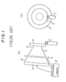
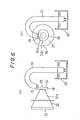
- the horn construction of a typical such ultrasonic atomizing inhaler is shown in Fig. la of the accompanying drawings in side view, and in Fig. lb in an end on view.
- the cone shaped horn construction e serves for concentrating ultrasound waves produced at its larger end a by the vibration of an ultrasonic oscillating element c which is driven by an oscillation circuit g, into its smaller end b, so as to vibrate an oscillating plate d integrally formed at its said smaller end b.
- a supply of liquid such as medicine is held in a storage bottle (not shown), and is picked up therefrom by a wick construction or absorptive bar f and is delivered little by little to the oscillating plate d by capillary action, whence it is atomized into the air by the vibrations of said oscillating plate d, to drift into the mouth and the throat and lungs of a user.
- the horn construction b is held in place by a flange h which is connected to a main body (not shown) of the inhaler.
- the oscillation member such as the plate d is typically a circular plate or disk, and proper atomization is possible only when the oscillation frequency produced by the oscillation circuit g and the resonance frequency of the oscillation plate d are well matched, so that said plate d becomes excited.
- the resonance frequency of the oscillation plate d with the load of liquid thereon accordingly changes, whereby the atomization action is weakened.
- the oscillation plate of the horn of a conventional ultrasonic atomizer is circular, it can have only one basic resonance frequency, and accordingly only can satisfactorily perform atomization at one frequency and at one particle size, with respect to a particular type of medication. Therefore, in order to change the average particle size of the atomized particles, it is necessary to prepare a plurality of ultrasonic atomizers (or, at least, horn assemblies) having different resonance frequencies.
- a flange has been integrally formed around the circumferential direction of the horn main body at a longitudinal position therealong corresponding to a node of the longitudinal oscillations thereof, said flange being coupled to said main body of said inhaler by its outer periphery being fitted into a groove therein (this structure is suggested in Fig.
- the mass and the dimension of the horn of a typical such ultrasonic atomizing inhaler, and particularly of the horn of such an inhaler intended for home use have become so small that, when an oscillation of frequency from 100 kHz to 300 kHz is to be produced in such a horn, although it may be possible in theory to compute an oscillation nodal point to be used as a support point, if a flange or groove is to be provided at said point as mentioned above, the dimensional precision of such a flange or groove must be very high. Accordingly, the machining process is caused to be very difficult, and accordingly the cost is raised. This problem has been a serious obstacle to providing an ultrasonic inhaler which is economical enough for home use.
- Figs. 12 and 13 of the appended drawings in side view: for the conical type horn assembly of Fig. 12, two lead wires 9a and 9b are soldered at their one ends to appropriate points on a circuit base board 8, and at their other ends, respectively, to an end surface of the ultrasonic oscillation element 3, and to a side wall 1 of the conical horn assembly. And, in a similar way, in the step type horn assembly of Fig.
- two lead wires 20a and 20b are soldered at their one ends to appropriate points on a circuit base board 19, and at their other ends, respectively, to an end surface of the ultrasonic oscillation element 3, and to a side wall 11 of the step type horn assembly.
- Another type of problem that occurs with ultrasonic atomizing inhalers of this sort has related to heating up of the horn assembly.
- the temperature of the horn assembly rises sharply during the action of the ultrasonic oscillation element, and may attain a level close to 100°C. Therefore, such heating up could cause an adverse effect in the adhesion portion between the horn assembly and the ultrasonic oscillation element, in the worst case causing peeling off of the ultrasonic oscillation element and damaging the oscillation capability of the horn assembly.
- an oscillating construction for an ultrasonic atomizing inhaler comprising an oscillation element which is excited to vibrate ultrasonically, wherein said oscillation element comprises two adjoining regions which have substantially different vibrational characteristics.
- liquid supply is made to one of the regions having substantially different vibrational characteristics, and the oscillation for atomization takes place in the other region, according to the particular frequency of ultrasonic excitation of the oscillation element which is appropriately chosen.
- the region to which liquid is supplied has a resonance frequency which is different from that of the region for atomization, and substantially no atomization takes place in the liquid supply region. Therefore, even when the load imposed on the oscillation element by liquid thereon has changed, as for example if the amount of the liquid on the liquid supply region thereof has changed, the oscillation of a constant frequency continues in the atomization region, and thereby proper atomization is maintained.
- an ultrasonic atomizer which effects proper supply of liquid to be atomized, which does not cause oversupply or undersupply of liquid to be atomized, and which further can handle fluids of various different viscosities, including even quite viscous liquid, and is not wasteful of atomization liquid.
- this ultrasonic atomizer is not uneconomical during use. Further, it is not prone to dribbling of atomization liquid, and thus is not liable to cause a mess.
- an oscillating construction for an ultrasonic atomizing inhaler as described above, further comprising a means for exciting said oscillation element so as to cause it to vibrate ultrasonically, selectable to either of two different frequencies.
- the oscillation means when the oscillation means is selected to oscillate at one of the frequencies and the ultrasonic oscillation element is driven by it, one of the two regions corresponding to this frequency alone oscillates, so that atomization is performed by this region, but when the oscillation means is selected to oscillate at the other frequency, then accordingly the other region of the ultrasonic oscillation element oscillates, and this region performs the atomization action. Since the two regions of the oscillation element have different oscillation frequencies, the two regions can perform atomization to produce different particle diameters.
- an oscillating construction for an ultrasonic atomizing inhaler comprising: a horn assembly, formed as a metallic unitary rigid body, having a major diameter end and a minor diameter end with an atomization portion formed thereon, and with a plurality of small holes formed around the circumferential direction of said horn assembly at points which are nodes with regard to longitudinal oscillation of said horn assembly; an ultrasonic oscillation element mounted on said major diameter end of said horn assembly; and a circlip the outer periphery of which is supported, with inwardly projecting portions which are engaged into said small holes to support said horn assembly.
- the horn assembly is supported at a plurality of points by the holes of the horn assembly and by the inwardly projecting engagement portions of the E ring. Therefore, the supporting means has very little influence on the longitudinal mode oscillation of the horn assembly, and further the machining work for the horn assembly during manufacture is simple, because all that is required is the drilling of these small holes in the horn.
- an oscillating construction for an ultrasonic atomizing inhaler comprising: a horn assembly,. formed as a metallic unitary rigid body, having an atomization portion formed thereon and an ultrasonic oscillation element, remote from said atomization portion, mounted on a mounting portion thereof; wherein: a shaft portion is erected at a central portion of said mounting portion of said horn assembly integrally therewith, extending away from the direction of the atomization portion, and said ultrasonic oscillation element is fitted over said shaft portion and is securely attached to said mounting portion of said horn assembly, said shaft portion being supported by a base board of said inhaler so as to keep said base board and said ultrasonic oscillation element are mutually separated.
- the horn assembly since no flange or groove for support is required to be provided in the horn assembly main body, the horn assembly therefore becomes relatively simple in shape. As a result, machining becomes simpler and the adverse influences from.a flange or groove on the oscillation mode are reduced. Furthermore, since the ultrasonic oscillation element may be attached to the horn assembly by fitting an annular hole formed in it over said shaft portion for guide action and then may be securely attached, positioning and adhesion of the ultrasonic oscillation element become relatively simple. Furthermore, one end surface of the ultrasonic oscillation element can be electrically connected to a base board by way of the shaft portion, which accordingly can additionally serve as an electrical connection member.
- the heat from the horn assembly is transmitted to the heat dissipation member for heat dissipation by way of the shaft portion of the horn assembly which is supported on the base board for supporting said horn assembly, thus without causing any ill effect on the oscillation of the horn assembly.
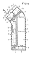
- Fig. 4 is a longitudinal sectional view of an ultrasonic atomizing inhaler which incorporates the first preferred embodiment of the oscillating construction of the present invention.
- reference numeral 1 generally denotes the ultrasonic inhaler as a whole, and this is made up of a main body assembly 2, a liquid supply assembly 3, and an inhalation unit 4.
- the main body assembly 2 defines the external contour of the ultrasonic inhaler, and comprises a main body casing 5 and a bottom plate 6.
- a pair of batteries 9, 9 in a battery receiving portion thereof, and a power plug 8 with a power source circuit board 7 is further held within the main body casing 5 below said batteries 9, 9.
- the bottom plate 6 serves for closing the bottom of the main body casing 5 and for retaining the batteries 9, 9 and the power plug 8 therein.
- An oscillation circuit base board 11 is fitted parallel to the batteries 9, 9 at one side thereof, and bears an electronic circuit unit 10 including for example an oscillation circuit, as will be described later.
- a micro switch 12 is provided for controlling the apparatus, and is covered by a slidable switch cover 15.
- a drive circuit base board 14 is provided at the top end of the main body 5, just below a top wall portion 5a thereof, for driving an oscillation element 13 which will be particularly described hereinafter.
- the liquid supply assembly 3 On the other side of the top wall portion 5a are provided the liquid supply assembly 3 and the inhalation unit 4.
- the liquid supply assembly 3, which will be discussed in greater detail later, comprises a storage bottle 16 for containing water or liquid medication and a liquid supply nozzle 17 fitted into said storage bottle 16 for allowing the controlled removal of liquid therefrom to the inhalation unit 4.
- the inhalation unit 4 comprises an inhalation nozzle 20 adapted to be approached to the nose and mouth of a user, and a horn unit 19 which has an oscillating atomization plate 18 integrally formed at the small end 32 of a rigid cone shaped portion 19a and an ultrasonic oscillation element 13 fitted at the larger end 31 of said rigid cone shaped portion 19a.
- the main body casing 5, the bottom plate 6, the switch cover 15, and the hygienic cap 21 are made of a material such as ABS resin, while the storage bottle 16, the liquid supply nozzle 17, and the inhalation nozzle 20 are made of a material such as styrene resin.
- the horn unit 19 is mounted at the lower portion of the top wall portion 5a of the main body casing 5 of the ultrasonic inhaler, with the ultrasonic oscillating element 13 facing towards the inside and the oscillating atomization plate 18 facing outwards, and the inhalation nozzle 20 is detachably mounted to said top wall portion 5a over said horn unit 19 with its opening confronting the oscillating plate 18 and facing outwards.
- the storage bottle 16 is detachably mounted at the upper portion of the top wall portion 5a, with the liquid supply nozzle 17 fitted thereinto substantially positioned at the lowest point thereof, and with the lower end of said liquid supply nozzle 17 positioned very close to the oscillating atomization plate 18 as will be explained hereinafter in detail.
- the oscillation circuit of the electronic circuit unit 10 drives the ultrasonic oscillating element 13 of the horn unit 19 to oscillate at an ultrasonic frequency, as will be particularly described later, and this causes the atomization plate 18 to similarly oscillate with a considerable amplitude, due to the amplifying effect provided by the rigid cone shaped portion 19a.
- a controlled supply of the liquid in the storage bottle 16 is provided to this atomization plate 18, and thus the vibration at ultrasonic frequency of the oscillation plate 18 atomizes this liquid into very minute droplets, which drift away from the atomization plate 18 in the direction indicated by the arrow A in Fig. 4 through the inhalation nozzle 20 to enter the mouth and nose of the user of the ultrasonic inhaler 1, as desired, to provide medication and/or humidification of the user's larynx.
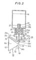
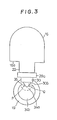
- Fig. 2 there is shown a sectional view of the bottle 16, the nozzle 17 fitted thereinto, and the horn unit 19 taken in the same plane as in Fig. 4, but in enlarged scale; and Fig. 3 shows these parts as fitted to the top wall portion 5a of the main body casing 5.
- the storage bottle 16 is shaped in an inverted U shape as seen from the front, as in Fig. 3, and further is shaped in a rectangular shape as seen from the side as in Fig. 3. As previously mentioned, the bottle 16 is formed from a transparent or translucent styrene resin. And from the bottom surface 16a of the storage bottle 16 there projects a tubular nozzle fitting member 22.
- this tubular nozzle fitting member 22 there is fitted the aforementioned liquid supply nozzle 17, with the interposition therebetween of a tube 23 made of a rubber like elastic material.
- This tube 23 is required to be somewhat distended, in order to be fitted over the nozzle 17, and further is then required to be somewhat compressed, in order for the nozzle 17 with said tube 23 fitted thereover to be fitted into the nozzle fitting member 22; accordingly, when this fitting has been accomplished, the inner cylindrical surface of the tube 23 is closely and sealingly contacted to the portions of the outer surface of the nozzle 17 with which it is in contact, and the outer cylindrical surface of said tube 23 is similarly closely and sealingly contacted to the inner cylindrical surface of the tubular nozzle fitting member 22. And thereby the nozzle 17 is securely held in said nozzle fitting member 22.
- This nozzle 17 has a generally cylindrical shape, with a flange 28a formed near its one end 30 which is outside the storage bottle 16 and another smaller flange 28b formed near its other end 23 which is inside said storage bottle 16.
- the tube 23 is fitted between these two flanges 28a and 28b and is axially retained between them.
- the larger lower flange 28a further serves for locating the nozzle 17 relative to the bottle 16, when said nozzle is fitted into the tubular nozzle fitting member 22 of said bottle 16.
- a plurality of circumferential grooves 26 are formed as extending round the portion of the nozzle 17 between said two flanges 28a and 28b; and a pair of liquid supply grooves 24 extending in the axial direction of the nozzle 17, thus being orthogonal to the circumferential grooves 26, and spaced diametrically opposite from one another around said nozzle 17, are formed as cut quite deeply into the material of said nozzle 17; these liquid supply grooves 24 are extremely fine, for proper obtaining of capillary action as will be explained hereinafter, and function for leading liquid from the interior of the storage bottle 16 to the atomization plate 18 of the horn assembly 19.
- the circumferential grooves 26 are provided for forming temporary storage reservoirs for fluid which is being taken out from the storage bottle 16 through the liquid supply grooves 24, as will be explained in greater detail later. And through the two flanges 28a and 28b and through the flange portions remaining between the grooves 26 on either side thereof there are cut, superimposed upon the outer portion of the liquid supply grooves 24 and wider than said liquid supply grooves 24, two air supply grooves 25; these air supply grooves 25 are substantially wider than the liquid supply grooves 24, and function for leading air from the outside to the interior of the storage bottle 16.
- the end 27 of the liquid supply nozzle 17 inside the storage bottle 16 is quite long, and has the continued end portion of the liquid supply grooves 24 formed on it, thus appropriately leading said liquid supply grooves 24 well into the liquid inside said bottle 16.
- the lower end 30 of the liquid supply nozzle 17 is formed with two projecting end portions 29a and 29b separated by the two liquid supply grooves 24: the longer projecting end portion 29b is substantially longer than the other portion 29a, being formed in a substantially triangular shape, and its inside surface 29d is substantially planar; while the shorter projecting end portion 29a is cut off straight, having a substantially straight downwardly facing edge 29c.
- the horn unit 19 comprises the rigid cone shaped portion 19a, and at the larger end 31 of said portion 19a is fitted the ultrasonic oscillation element 13.
- the oscillating atomization plate 18 At the smaller end 32 of said rigid cone shaped portion 19a there is integrally formed the oscillating atomization plate 18, in an orientation perpendicular to the axis of said cone shape thereof; and this atomization plate 18 is in this first preferred embodiment of the present invention formed as a disk with a portion thereof defined by a chord 35 cut away, leaving the remainder 33 of its circumferential circle intact.
- the surface 34 of the plate 18 facing away from the cone shaped portion 19a is substantially planar. As best shown in Fig.
- the horn unit 19 is so mounted to the top wall portion 5a of the main body casing 5, relative to the storage bottle 16, that this surface 34 of said atomization plate 18 confronts the aforementioned substantially planar inside surface 29d of the longer projecting lower end portion 29b of the liquid supply nozzle 17 with a certain very narrow gap 36 being defined therebetween. And, moreover, in this position the edge of the plate 18 defined by the chord 35 confronts the flat lower edge 29c of the shorter projecting end portion 29a of the liquid supply nozzle 17 with another very narrow gap 37 being defined therebetween.
- the atomization plate 18 is formed with a boundary divided into two parts, which are generally at different distances from the center of said atomization plate 18.
- the surface 34 of said-atomization plate 18 can be considered as made up of two regions 34a and 34b: the region 34a is the one principally delimited by the chord line 35, while the other region 34b is the one principally delimited by the remainder 33 of the circumference of the disk shape of said atomization plate 18.
- the boundary between these two regions is necessarily conceptually vague, and it is accordingly indicated in Fig. 3 by a dashed line.
- the atomization plate 18 is caused to vibrate at ultrasonic frequency as explained above; or, more exactly, the region 34b of said atomization plate 18, which is the one principally delimited by the remainder 33 of the circumference of the disk shape of said atomization plate 18, is caused to vibrate at high amplitude, since the frequency of the ultrasonic excitation provided to the ultrasonic oscillating element 13 by the oscillation circuit of the electronic circuit unit 10 is so chosen; but, since the region 34a of the atomization plate 18 which is principally delimited by the chord line 35 has a different fundamental frequency, it does not vibrate so much or with such a high amplitude.
- liquid in the storage bottle 16 passes by the action of gravity and also by capillary action from the interior of said bottle 16, into the upper ends of the liquid supply grooves 24 where they are formed in the inwardly projecting portion 27 of the nozzle 17, and down through these grooves 24.
- the two circumferential grooves 26 define intermediate fluid reservoirs along this fluid flow path, said reservoirs being communicated to the sides of the grooves 24 at intermediate points therealong.
- the liquid flows to the outside of the bottle 16 down through the portions of the liquid supply grooves 24 formed in the outwardly projecting portion 30 of the nozzle 17, and therefrom flows to the surfaces 29c and 29d of the projecting end portions 29a and 29b, from which it flows across the narrow gaps 37 and 36 respectively, to the surface 34 of the atomization plate 18 - in particular, to the region 34a thereof which is principally delimited by the chord line 35, and which, as explained above, is not vibrating with a very great amplitude.
- the supplied liquid quickly creeps to the other region 34b, which is the one principally delimited by the remainder 33 of the circumference of the disk shape of said atomization plate 18, and which as explained above is vibrating at an ultrasonic frequency with a comparatively great amplitude.
- this liquid is atomized by the vibration at ultrasonic frequency of said portion 34b of the atomization plate 18, and drifts away from said plate 18 to pass through the aperture of the inhalation nozzle 20, in the direction indicated in Fig. 4 by the arrow A, to enter the mouth and nose of the user of the ultrasonic inhaler 1.
- an amount of air substantially equal in volume to the amount of fluid thus taken out from the bottle 16 enters into the interior of said bottle 16 through the two air supply grooves 25.
- a relatively large volume of liquid may be satisfactorily supplied by the action of gravitation and by capillary action through the two liquid supply grooves 24, and since further reservoirs of liquid en route are provided by the circumferential grooves 26, this supply of liquid to be atomized is performed smoothly and efficiently, according to the amount required, and interruption of liquid supply is never likely to occur.
- the area of the atomization plate 18 utilized for atomization is broadened. Furthermore, even when the conditions of liquid supply, such as the volume thereof, or the viscosity of the liquid and so on, at the non strongly vibrating region 34a of the oscillation plate 18 have changed, since this portion of the oscillation plate 18 does not substantially contribute to the atomization action for the liquid, no problems arise, and the oscillation of the strongly vibrating region 34b of said atomization plate 18 is not substantially influenced or affected. Therefore, even when the load imposed on the oscillation plate 18 by the liquid changes, the resonance frequency of the operative portion thereof, i.e. of the strongly vibrating region 34b thereof, is not substantially altered, and the atomization action can be maintained.
- this second preferred embodiment of the present invention has the same advantages as outlined above with regard to the first preferred embodiment.
- Figs. 6a and 6b there are shown the horn assembly 19 and the liquid supply system relating to a third preferred embodiment of the present invention.
- the orientation of the atomization plate 18 is the same as the orientation of the corresponding atomization plate of the first preferred embodiment of the present invention as shown in Figs. 2 and 3, and is opposite to that of the second preferred embodiment.
- parts which correspond to parts of the first preferred embodiment shown in Figs. 2 through 4 and discussed above, and of the second preferred embodiment shown in Figs. 5a and 5b, and which have the same functions, are denoted by the same reference symbols.
- the liquid is supplied, by an absorptive bar 51 this time which is shaped in an inverted J shape and leads said liquid by capillary action from a tank 50, to a region 34a of the surface 34 of the atomization plate 18 which is not vibrating with a very great amplitude. From this region 34a, the supplied liquid quickly creeps to the other strongly vibrating region 34b. Then, as outlined previously, this liquid is atomized and drifts away to enter the mouth and nose of the user.
- this third preferred embodiment of the present invention has the same advantages as outlined above with regard to the first and second preferred embodiments.
- Figs. 6a and 6b there are shown the horn assembly 19 and the liquid supply system relating to a fourth preferred embodiment of the present invention.
- the horn assembly is configured differently, being a stepped shape horn 60; however, the oscillating plate 18 is of the same type as in the first through the third preferred embodiments discussed above.
- parts which correspond to parts of the first through third preferred embodiments shown in Figs. 2 through 6 and discussed above, and which have the same functions, are denoted by the same reference symbols.
- the liquid is supplied by an absorptive bar 64 to a region 34a of the surface 34 of the atomization plate 18 which is not vibrating with a very great amplitude.
- this fourth preferred embodiment operates will be clear to one of ordinary skill in the ultrasonic atomizer art, based upon the disclosure hereinabove, and hence will not be expatiated upon; and it has the same advantages as outlined above with regard to the first through the third preferred embodiments.
- the oscillation plate 18 is formed as a rectangular m ember with long sides and short sides.
- the oscillation plate comprises two regions having different vibrational characteristics, and in the shown preferred embodiments having different distances between their edges and their center, by supplying liquid to one of the regions and producing atomization action in the other region, the fluctuations in the load imposed by the liquid do not affect the atomization action, whereby an ultrasonic atomizer which is immune to fluctuations in load can be obtained. Furthermore, since the liquid is supplied to the oscillation plate in two directions separately (from the regions around the points P and Q in Fig. 3), the oscillation surface of the oscillating plate is well utilized, and the atomization efficiency is improved.
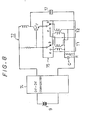
- Fig. 8 shows a circuit diagram for a drive circuit 72 on the base board 14-for driving the oscillation element 13, which is provided at the top end of the main body 5 just below the top wall portion 5a thereof, in a fifth preferred embodiment of the present invention; the remainder of this fifth preferred embodiment is like the first preferred embodiment shown above and described with reference to Figs. 2 through 4, and hence will not be described in detail.
- the voltage of the batteries 9 is raised by a DC - DC converter 74 and is supplied as a power source voltage to this drive circuit 72.
- the drive circuit 72 is a per se known type of blocking oscillator, and comprises a transistor Tr, _a pair of transformers Tl and T2, a capacitor C, a resistor R, and so on, and by the action of a switch 75 it is possible to select one of the transformers Tl and T2 for use therein. In other words, depending upon whether the switch 75 is set to the a side or to the b side, one or the other of the transformers Tl and T2 of the oscillation circuit 72 is selected, and thus the oscillation circuit 72 can oscillate at two different frequencies.
- the frequencies which may be switched over are designed so as to correspond to the resonance frequencies of the portion 34a of the oscillation plate 18 largely delimited by the chord 35 and the other portion 34b of said oscillation plate 18 largely delimited by the remainder 33 of the circumference of the disk shape thereof.
- the switch 75 when the switch 75 is set to the side a or to the side of the transformer Tl, and the power is turned ON for starting oscillation for instance at the higher of the two frequencies, the ultrasonic oscillation element 13 oscillates at this higher frequency, and the ultrasonic waves thereby generated are transmitted through the main body 19a of the horn assembly 19 to the oscillation plate 18, causing the portion 34a thereof largely delimited by the chord 35 to vibrate strongly; and thus the liquid existing adjacent to said portion 34a is atomized.
- the switch 75 when the switch 75 is set to the side b or to the side of the transformer T2, the oscillation circuit 72 starts oscillating while connected to the transformer T2.
- the ultrasonic oscillation element 13 oscillates at a frequency which is lower than the one which was produced when the switch 75 was selected to the side of the transformer Tl. Accordingly, this time, the other portion 34b of said oscillation plate 18 largely delimited by the remainder 33 of the circumference of the disk shape of the oscillation plate 18 oscillates. And the liquid existing adjacent to this other portion 34b is atomized. And, since the resonance frequencies of the two portions 34a and 34b differ from each other, the resulting particle diameters of the atomized liquid also differ.
- the horn was of a conical type in the above described fifth preferred embodiment, the concept thereof could be likewise implemented by using horns of other types, such as a step horn and so on.
- the oscillation plate was defined into two regions having different resonance frequencies by cutting off a portion of a circular plate delimited by a chord in the above described embodiment, it is also possible to define the atomization portion with a rectangular shape having long sides and short sides, so as similarly to define two regions having different resonance frequencies.
- supply of liquid to the atomization portion was made by an absorptive band, it is also possible to use other means such as a liquid supply nozzle and so on.
- the ultrasonic inhaler can perform the treatment of both the deep part of the trachea and the shallow part of the larynx, according to the current medical requirements, and the present invention can further be adapted to a wide variety of medications.
- Fig. 9a there is shown a side view
- Fig. 9b there is shown an end on view, of a sixth preferred embodiment of the present invention; again, like parts are denoted by like reference numerals.
- This structure is intended for use with a two frequency type of drive circuit 72 like that of Fig. 8, and differs from the previous ones in that the oscillation plate 18 is formed as a disk shape with two diametrically opposite portions cut away by two chords, so as to define two portions 34a thereof largely delimited by the chord 35 which tend to vibrate at one characteristic frequency and one intermediate portion 34b of said oscillation plate l8 largely delimited by the remainder 33 of the circumference of the disk shape thereof which tends to vibrate at the other characteristic frequency.
- the effects and advantages are the same as in the fifth preferred embodiment described above, and hence detailed discussion thereof will be omitted.
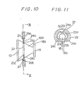
- FIG. 10 there is shown a schematic partly sectional side view of the horn assembly 19, and of the support construction therefor, in a seventh preferred embodiment of the present invention; in this construction, like parts to parts in the previous embodiments are not necessarily denoted by like reference numerals. And, in Fig. 11, a sectional view of these portions of this seventh preferred embodiment taken in a plane indicated by the arrows XI - XI in Fig. 10 is shown.
- the support construction for the horn 19 in this embodiment of the present invention will now be described.
- Three small holes 23a, 23b, and 23c are formed around the body 19a of the horn assembly 19 spaced apart at intervals of about 120° in the circumferential direction, at a longitudinal position therealong which corresponds to a nodal point of the longitudinal oscillation of said horn assembly 19. And inwardly projecting engagement portions 24a, 24b, and 24c of an E ring or circlip 22 are respectively engaged with these small holes 23a, 23b, and 23c.
- the upper wall portion 5a of the main body case 5 of the ultrasonic inhaler (see Fig. 4) is divided into two case halves 5b and 5c, and each half is provided with a groove 26b and 26c respectively of a semi circular shape for supporting the outer periphery 27 of the E ring 22.
- each of the grooves 26a and 26b of the main body case halves 5b and 5c are made asymmetrically so as to be adapted to the shape of the E ring 22, and if the E ring 22 is positioned in an inverted orientation said E ring 22 cannot be properly fitted into the grooves 26 and 26. Therefore, when the small holes 23a, 23b, and 23c of the horn 19 are engaged to the engagement pieces 24a, 24b, and 24c of the E ring 22, once the E ring 22 is properly fitted into the grooves 26a and 26b of the main body case 26, the horn 19 is definitely guaranteed to be properly positioned and supported on the main body case 5.
- the oscillation plate 18 is provided with a cut away portion 18a as indicated by a broken line, as in the previously outlined embodiments of the present invention, it becomes possible to align the cut away portion 18a properly with the liquid supply nozzle 17 (not shown, but as described above) by means of the above mentioned positioning means, thus obtaining a great constructional advantage.
- the support mechanism for the horn assembly 19 because the horn assembly 19 is supported at three points by the three small holes of the horn main body 19a and by the three corresponding projections on the E ring, as compared to the case in which a conventional flange or groove is used for support, the load imposed on the longitudinal oscillation mode of the horn assembly 19 is reduced, and the consequent influence on the acoustic properties and the impedance properties of said horn assembly 19 is reduced, so that the atomization efficiency may be increased. Since it is only necessary to drill small holes in the horn assembly 19, the machining is simple, and it becomes possible to provide an ultrasonic atomizer which is economical as a whole.
- FIG. 14 there is shown a schematic longitudinal sectional view of the horn assembly 19, and of the support construction therefor, in an eighth preferred embodiment of the present invention; in this construction, like parts to parts in the previous embodiments are not necessarily denoted by like reference numerals. And, in Fig. 15, a sectional view of these portions of this eighth preferred embodiment as fitted to the base board 14 of the ultrasonic atomizing inhaler and thus mounted is shown.
- the support construction for the horn assembly 19 in this embodiment of the present invention will now be described.
- the main body of the horn assembly 19 is made as a metallic rigid body, and has a conical shape as in previous embodiments. Its minor diameter end is provided with an atomization plate 18, while a central -portion of its major diameter end is provided with a shaft portion 84 which projects in a direction opposite to the atomization plate 18. A middle portion of this shaft portion 84 is provided with a flange 85 for positioning the horn assembly 19 when supporting the horn assembly 19 on the base board 14 of the drive circuit for the ultrasonic inhaler, and a step portion 86 which has substantially the same diameter as this flange 85 is provided at the base end of this shaft portion 84, abutting the major diameter end of the horn assembly 19.
- the shaft portion 84 may guide the ultrasonic oscillation element 13 so that the ultrasonic oscillation element 13 may be adhered to an end surface of said major diameter end of the horn assembly 19 in proper alignment.
- the shaft portion 84 is passed through a hole in the circuit base board 14 from the left hand of the base board 14 and, when the flange 45 engages the base board 14, the horn assembly 19 is secured by fastening a nut 88 on the screw threaded projecting end of said shaft portion 84.
- one of the electrodes, i.e. the left electrode as seen in Fig. 14, of the ultrasonic oscillation element 13 is connected to a point of the electrical pattern printed on the circuit base board 14 by way of the shaft portion 84 of the horn assembly 19.
- the horn assembly 19 may be supported on the main body case of the ultrasonic inhaler by way of a cushion ring made of rubber or the like fitted at a nodal point thereof:
- Fig. 16 shows the case in which the horn assembly 19 is step shaped, as opposed to the conical horn assembly 19 of Fig. 14, and this ninth preferred embodiment is supported in substantially the same way as that of Fig. 14 and 15.
- the shaft portion acts as a guide when mounting the ultrasonic oscillation element to the horn assembly, and guides the ultrasonic oscillation element by its annular hole, the ultrasonic oscillation element may be adhered with a proper positioning to the horn assembly, and accordingly misalignment of the oscillation element may be avoided.
- the horn assembly according to these embodiments of the present invention does not require any flange or groove to be formed in the side wall of the main body of said horn assembly for support, the shape of said main body of said horn assembly is simplified, and through improved facility of machining a horn assembly of high precision may be obtained.
- the shaft portion for supporting the horn assembly can be used also as one of the lead wires for driving the ultrasonic oscillation element, thereby the means such as a partition for supporting the horn oscillation unit and the circuit base board may be consolidated into one.
- a horn assembly of the above type is made of stainless steel in consideration of corrosion resistance and pressure resistance, and conventionally soldering on such a horn assembly has not been well controllable in terms of the quantity of solder used, thereby giving rise to various problems of quality control. However, this point is also improved upon, according to this invention.
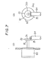
- FIG. 17 there is shown a schematic longitudinal sectional view of the horn assembly 19, and of the support construction therefor, as fitted to the base board 14 of the ultrasonic atomizing inhaler and thus mounted, in an tenth preferred embodiment of the present invention; in this construction, like parts to parts in the previous embodiments are not necessarily denoted by like reference numerals.
- the support construction for the horn assembly 19 in this embodiment of the present invention will now be described.
- the main body of the horn assembly 19 is conical in shape as in many of the previous embodiments, and its minor diameter end is formed with the atomization portion 18, while a central portion of its major diameter end is provided with a shaft portion 84 which projects away from the atomization portion 18 in a projecting manner.
- a step portion 86 is provided in the base portion of this shaft portion 84, and a flange 85 of substantially the same diameter as said step portion 86 is formed at an intermediate position on the shaft portion 84.
- the annular shaped ultrasonic oscillation element 13 is fitted over the shaft portion 84 and is adhered to an end surface of the major diameter end of the horn assembly 19.
- the shaft portion 84 is fitted through a hole provided in the base board 14 and is fixedly secured to the base board 14 with the flange 85 and a screw 87 clamping said base board 14 between them.
- a fin 90 for heat dissipation is fixedly secured by the screw 87 to the shaft portion 84, on the other side of said base board 14 from the horn assembly 19.
- the ultrasonic inhaler With the ultrasonic inhaler incorporating this horn assembly, when the action is started and the ultrasonic oscillation element 13 starts oscillation, its oscillation energy is transmitted through the main body of the horn 19 and is concentrated on the atomization portion 18 for atomization action.
- the horn 19 becomes hot from this oscillation, the heat is efficiently dissipated to the space in the main body casing from the fin 90 by way of the shaft portion 84. Therefore, rising of the temperature of the horn assembly 19 is controlled, and peeling off of the ultrasonic oscillation element 13 from the horn assembly 19 is avoided.
- Fig. 18 is a drawing showing an eleventh preferred embodiment, in which a step shaped horn assembly 19 is supported instead of the conical horn assembly 19 of the tenth preferred embodiment shown in Fig. 17, and this embodiment does not differ from the one shown in F ig. 17, except in that the shape of the horn assembly 19 is different.
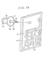
- a fin 90 was used as the heat dissipation member, it is also possible to use a portion of the ground wiring metallic layer 91 of the wiring pattern 92 formed as a printed circuit on the base board 14 as the heat dissipation member; this is schematically shown in perspective view, as the twelfth preferred embodiment of the present invention, in Fig. 19 in perspective view. By doing so, without providing any special fin for heat dissipation, a very high heat dissipation efficiency may be obtained, because the whole pattern of the ground wiring metallic layer 30 can be used as a heat dissipating surface.
- the ultrasonic atomizer of this aspect of the present invention since heat dissipation is performed by the heat dissipating member which is supported on the base board, by way of the shaft portion, without providing the heat dissipation member directly on the horn assembly main body and without thus disrupting the oscillation of the horn assembly, the horn assembly is well cooled and the durability of the oscillation construction may be extended.
- FIG. 20 there is shown a schematic longitudinal sectional view of the horn assembly 19, and of the support construction therefor, as fitted to the base board 14 of the ultrasonic atomizing inhaler and thus mounted, in an thirteenth preferred embodiment of the present invention; in this construction, like parts to parts in the previous embodiments are not necessarily denoted by like reference numerals.
- the support construction for the horn assembly 19 in this embodiment of the present invention will now be described.
- the horn assembly 19 is made as a metallic rigid body as in previous embodiments, and its minor diameter end is integrally formed with an atomization portion or oscillation plate 18, while a central portion of its major diameter end has a shaft portion 84 which projects away from the atomization portion 18 or towards the circuit base board 14.
- a middle portion of this shaft portion 84 is provided with a flange 85 for positioning the horn 19 when supporting it on the base board 14, and a step portion 86 of the same diameter as the flange 85 is provided in the base portion of the shaft portion 84.
- the ultrasonic oscillation element 13 which is annular in shape is fitted over the shaft portion 84, and one of its electrodes 13a is adhered and electrically connected to the end surface of the major diameter end of the horn 19.
- the shaft portion 84 is fixedly secured to the circuit base board 14 by the flange 85 and the nut 87 and is thus electrically connected to a grounding wire portion of the wiring pattern or printed circuit formed on the circuit base board 14.
- one of the electrodes 13a of the ultrasonic oscillation element 13 is connected to the minus side of an appropriate electrical circuit.
- the horn assembly 19 is supported by the main body of the ultrasonic inhaler without said horn assembly 19 being disturbed with regards to its oscillation which is necessary for proper atomization performance.
- Contact pieces 98a and 98b are soldered to the plus side of said electrical circuit on the circuit wiring pattern on the circuit base board 14, for applying positive voltage to the other electrode 13b of the ultrasonic oscillation element 13, and these contact pieces 98a and 98b contact said other electrode 13b of the ultrasonic oscillation element 13 by their inherent springiness and convey electricity thereto.
- the ultrasonic oscillation element 13 is connected to the positive and negative circuit portions of the circuit base board 14 by the contact pieces 98a and 98b and the shaft portion 84, and accordingly the ultrasonic oscillation element 13 is connected to the printed circuit on the circuit base board 14 without any lead wire requiring to be soldered to the ultrasonic oscillation element 13 or to the the horn assembly 19.
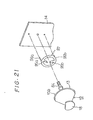
- Fig. 21 which is an exploded perspective view of the horn assembly 19 and of the support construction therefor as fitted to the base board 14 of the ultrasonic atomizing inhaler and thus mounted
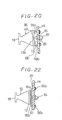
- Fig. 22 which is a sectional view similar to Fig. 20 relating to the thirteenth embodiment.
- the ultrasonic oscillation element is connected to the circuit base board by way of the horn assembly shaft portion and the contact pieces, as opposed to the conventional case in which direct soldering is made to the side surface of the horn assembly and/or to the electrodes of the ultrasonic oscillation element, soldering to the circuit base board is extremely simple, and the work required to electrically connect the ultrasonic oscillation element to the electric circuit becomes extremely simplified. Furthermore, because it is not necessary to solder or to attach extra lead wire to the circumferential side wall of the horn, the oscillation of the horn is not adversely affected by the (possibly hard to adequately control) weight of the mass of such solder.
Landscapes
- Health & Medical Sciences (AREA)
- Engineering & Computer Science (AREA)
- Bioinformatics & Cheminformatics (AREA)
- Pulmonology (AREA)
- Anesthesiology (AREA)
- Biomedical Technology (AREA)
- Heart & Thoracic Surgery (AREA)
- Hematology (AREA)
- Life Sciences & Earth Sciences (AREA)
- Animal Behavior & Ethology (AREA)
- General Health & Medical Sciences (AREA)
- Public Health (AREA)
- Veterinary Medicine (AREA)
- Special Spraying Apparatus (AREA)
Priority Applications (1)
| Application Number | Priority Date | Filing Date | Title |
|---|---|---|---|
| AT85111388T ATE61939T1 (de) | 1984-09-07 | 1985-09-09 | Schwingungserzeuger fuer ein inhalationsgeraet mit ultraschallzerstaeubung. |
Applications Claiming Priority (12)
| Application Number | Priority Date | Filing Date | Title |
|---|---|---|---|
| JP13628384U JPS6151968U (de) | 1984-09-07 | 1984-09-07 | |
| JP136283/84U | 1984-09-07 | ||
| JP18870284A JPS6168158A (ja) | 1984-09-07 | 1984-09-07 | 超音波霧化器 |
| JP188702/84 | 1984-09-07 | ||
| JP136311/84U | 1984-09-08 | ||
| JP13631184U JPS6151970U (de) | 1984-09-08 | 1984-09-08 | |
| JP13753384U JPS6151971U (de) | 1984-09-10 | 1984-09-10 | |
| JP137533/84U | 1984-09-10 | ||
| JP19227184A JPS6168060A (ja) | 1984-09-12 | 1984-09-12 | 超音波霧化器のホ−ン振動体 |
| JP192271/84 | 1984-09-12 | ||
| JP139891/84U | 1984-09-14 | ||
| JP13989184U JPS6155968U (de) | 1984-09-14 | 1984-09-14 |
Publications (3)
| Publication Number | Publication Date |
|---|---|
| EP0174033A2 true EP0174033A2 (de) | 1986-03-12 |
| EP0174033A3 EP0174033A3 (en) | 1987-09-02 |
| EP0174033B1 EP0174033B1 (de) | 1991-03-27 |
Family
ID=27552869
Family Applications (1)
| Application Number | Title | Priority Date | Filing Date |
|---|---|---|---|
| EP85111388A Expired EP0174033B1 (de) | 1984-09-07 | 1985-09-09 | Schwingungserzeuger für ein Inhalationsgerät mit Ultraschallzerstäubung |
Country Status (3)
| Country | Link |
|---|---|
| US (1) | US4790479A (de) |
| EP (1) | EP0174033B1 (de) |
| DE (1) | DE3582287D1 (de) |
Cited By (4)
| Publication number | Priority date | Publication date | Assignee | Title |
|---|---|---|---|---|
| US5515841A (en) * | 1993-11-25 | 1996-05-14 | Minnesota Mining And Manufacturing Company | Inhaler |
| US6026809A (en) * | 1996-01-25 | 2000-02-22 | Microdose Technologies, Inc. | Inhalation device |
| US6142146A (en) * | 1998-06-12 | 2000-11-07 | Microdose Technologies, Inc. | Inhalation device |
| US6152130A (en) * | 1998-06-12 | 2000-11-28 | Microdose Technologies, Inc. | Inhalation device with acoustic control |
Families Citing this family (99)
| Publication number | Priority date | Publication date | Assignee | Title |
|---|---|---|---|---|
| DE69002087T2 (de) * | 1989-05-31 | 1994-01-13 | Conceptair Anstalt Vaduz | Verfahren und elektrische, elektronische und mechanische Vorrichtung zum Verteilen, Dosieren oder Diffundieren, von flüssigen oder gasförmigen Aromen, Arzneien und anderen flüssigen oder viskösen Produkten. |
| US5152456A (en) * | 1989-12-12 | 1992-10-06 | Bespak, Plc | Dispensing apparatus having a perforate outlet member and a vibrating device |
| US7628339B2 (en) | 1991-04-24 | 2009-12-08 | Novartis Pharma Ag | Systems and methods for controlling fluid feed to an aerosol generator |
| US6540154B1 (en) | 1991-04-24 | 2003-04-01 | Aerogen, Inc. | Systems and methods for controlling fluid feed to an aerosol generator |
| US5938117A (en) | 1991-04-24 | 1999-08-17 | Aerogen, Inc. | Methods and apparatus for dispensing liquids as an atomized spray |
| US6629646B1 (en) * | 1991-04-24 | 2003-10-07 | Aerogen, Inc. | Droplet ejector with oscillating tapered aperture |
| US5497763A (en) * | 1993-05-21 | 1996-03-12 | Aradigm Corporation | Disposable package for intrapulmonary delivery of aerosolized formulations |
| FR2705911B1 (fr) * | 1993-06-02 | 1995-08-11 | Oreal | Appareil de nébulisation piézoélectrique. |
| CH686872A5 (de) * | 1993-08-09 | 1996-07-31 | Disetronic Ag | Medizinisches Inhalationsgeraet. |
| US5435282A (en) * | 1994-05-19 | 1995-07-25 | Habley Medical Technology Corporation | Nebulizer |
| JPH0824739A (ja) * | 1994-06-29 | 1996-01-30 | Siemens Ag | 超音波噴霧器 |
| IL117474A (en) * | 1995-03-14 | 2001-04-30 | Siemens Ag | Removable precise dosing unit containing inhaled drugs for a hearing aid device |
| ZA962077B (en) * | 1995-03-14 | 1997-03-26 | Siemens Ag | Ultrasonic atomizer device with removable precision dosating unit |
| US6205999B1 (en) | 1995-04-05 | 2001-03-27 | Aerogen, Inc. | Methods and apparatus for storing chemical compounds in a portable inhaler |
| US6782886B2 (en) | 1995-04-05 | 2004-08-31 | Aerogen, Inc. | Metering pumps for an aerosolizer |
| US5586550A (en) * | 1995-08-31 | 1996-12-24 | Fluid Propulsion Technologies, Inc. | Apparatus and methods for the delivery of therapeutic liquids to the respiratory system |
| US5758637A (en) | 1995-08-31 | 1998-06-02 | Aerogen, Inc. | Liquid dispensing apparatus and methods |
| US6014970A (en) * | 1998-06-11 | 2000-01-18 | Aerogen, Inc. | Methods and apparatus for storing chemical compounds in a portable inhaler |
| US6085740A (en) | 1996-02-21 | 2000-07-11 | Aerogen, Inc. | Liquid dispensing apparatus and methods |
| DE69834210T2 (de) * | 1997-11-19 | 2007-01-04 | Microflow Engineering S.A. | Sprühvorrichtung für einen Inhalator |
| US6397838B1 (en) * | 1998-12-23 | 2002-06-04 | Battelle Pulmonary Therapeutics, Inc. | Pulmonary aerosol delivery device and method |
| US6378780B1 (en) | 1999-02-09 | 2002-04-30 | S. C. Johnson & Son, Inc. | Delivery system for dispensing volatiles |
| DE60008074T2 (de) | 1999-03-05 | 2004-07-08 | S.C. Johnson & Son, Inc., Racine | Steuersystem zur zerstäubung von flüssigkeiten mit einem piezoelektrischen schwinger |
| US6235177B1 (en) | 1999-09-09 | 2001-05-22 | Aerogen, Inc. | Method for the construction of an aperture plate for dispensing liquid droplets |
| EP1151758A3 (de) * | 2000-05-04 | 2002-07-10 | Geok Weng Kong | Mit einem Kompressor betriebener Handvernebler |
| US6948491B2 (en) | 2001-03-20 | 2005-09-27 | Aerogen, Inc. | Convertible fluid feed system with comformable reservoir and methods |
| US7971588B2 (en) | 2000-05-05 | 2011-07-05 | Novartis Ag | Methods and systems for operating an aerosol generator |
| US7100600B2 (en) | 2001-03-20 | 2006-09-05 | Aerogen, Inc. | Fluid filled ampoules and methods for their use in aerosolizers |
| MXPA02010884A (es) | 2000-05-05 | 2003-03-27 | Aerogen Ireland Ltd | Aparato y metodo para el suministro de medicamentos al sistema respiratorio. |
| US7600511B2 (en) | 2001-11-01 | 2009-10-13 | Novartis Pharma Ag | Apparatus and methods for delivery of medicament to a respiratory system |
| US8336545B2 (en) | 2000-05-05 | 2012-12-25 | Novartis Pharma Ag | Methods and systems for operating an aerosol generator |
| US6786518B2 (en) * | 2000-06-13 | 2004-09-07 | Southco, Inc. | Load floor latch |
| US6543443B1 (en) | 2000-07-12 | 2003-04-08 | Aerogen, Inc. | Methods and devices for nebulizing fluids |
| US6386462B1 (en) | 2000-07-31 | 2002-05-14 | S. C. Johnson & Son, Inc. | Method and apparatus for dispensing liquids in aerosolized form with minimum spillage |
| US6964647B1 (en) | 2000-10-06 | 2005-11-15 | Ellaz Babaev | Nozzle for ultrasound wound treatment |
| US6450419B1 (en) | 2000-10-27 | 2002-09-17 | S.C. Johnson & Son, Inc. | Self contained liquid atomizer assembly |
| US6601581B1 (en) | 2000-11-01 | 2003-08-05 | Advanced Medical Applications, Inc. | Method and device for ultrasound drug delivery |
| US6482863B2 (en) | 2000-12-15 | 2002-11-19 | S. C. Johnson & Son, Inc. | Insect repellant formulation deliverable by piezoelectric device |
| US6761729B2 (en) | 2000-12-22 | 2004-07-13 | Advanced Medicalapplications, Inc. | Wound treatment method and device with combination of ultrasound and laser energy |
| US6533803B2 (en) | 2000-12-22 | 2003-03-18 | Advanced Medical Applications, Inc. | Wound treatment method and device with combination of ultrasound and laser energy |
| US7914470B2 (en) | 2001-01-12 | 2011-03-29 | Celleration, Inc. | Ultrasonic method and device for wound treatment |
| US8235919B2 (en) | 2001-01-12 | 2012-08-07 | Celleration, Inc. | Ultrasonic method and device for wound treatment |
| US6960173B2 (en) | 2001-01-30 | 2005-11-01 | Eilaz Babaev | Ultrasound wound treatment method and device using standing waves |
| US6546927B2 (en) | 2001-03-13 | 2003-04-15 | Aerogen, Inc. | Methods and apparatus for controlling piezoelectric vibration |
| US6550472B2 (en) | 2001-03-16 | 2003-04-22 | Aerogen, Inc. | Devices and methods for nebulizing fluids using flow directors |
| US6623444B2 (en) | 2001-03-21 | 2003-09-23 | Advanced Medical Applications, Inc. | Ultrasonic catheter drug delivery method and device |
| US6478754B1 (en) | 2001-04-23 | 2002-11-12 | Advanced Medical Applications, Inc. | Ultrasonic method and device for wound treatment |
| US6732944B2 (en) | 2001-05-02 | 2004-05-11 | Aerogen, Inc. | Base isolated nebulizing device and methods |
| US6554201B2 (en) | 2001-05-02 | 2003-04-29 | Aerogen, Inc. | Insert molded aerosol generator and methods |
| JP2005503238A (ja) * | 2001-09-12 | 2005-02-03 | ノートン ヘルスケアー リミテッド | 呼吸促進超音波噴霧器および専用ユニット服用アンプル |
| ATE298600T1 (de) * | 2001-10-18 | 2005-07-15 | Pari Gmbh | Inhalationstherapievorrichtung |
| EP1304130B1 (de) * | 2001-10-18 | 2004-06-23 | PARI GmbH Spezialisten für effektive Inhalation | Inhalationstherapievorrichtung |
| MXPA04006629A (es) | 2002-01-07 | 2004-11-10 | Aerogen Inc | Aparatos y metodos para nebulizar fluidos para inhalacion. |
| US7677467B2 (en) | 2002-01-07 | 2010-03-16 | Novartis Pharma Ag | Methods and devices for aerosolizing medicament |
| JP4761709B2 (ja) | 2002-01-15 | 2011-08-31 | エアロジェン,インコーポレイテッド | エアロゾル発生器を作動するための方法およびシステム |
| US7045934B2 (en) * | 2002-04-11 | 2006-05-16 | Ernest Geskin | Method for jet formation and the apparatus for the same |
| AU2003256253A1 (en) | 2002-05-20 | 2003-12-02 | Aerogen, Inc. | Aerosol for medical treatment and methods |
| US6752327B2 (en) | 2002-10-16 | 2004-06-22 | S. C. Johnson & Son, Inc. | Atomizer with tilted orifice plate and replacement reservoir for same |
| US7469844B2 (en) | 2002-11-08 | 2008-12-30 | S.C. Johnson & Son, Inc. | Diffusion device and method of diffusing |
| US7017829B2 (en) | 2003-04-14 | 2006-03-28 | S. C. Johnson & Son, Inc. | Atomizer wicking system |
| US7883031B2 (en) | 2003-05-20 | 2011-02-08 | James F. Collins, Jr. | Ophthalmic drug delivery system |
| US8012136B2 (en) | 2003-05-20 | 2011-09-06 | Optimyst Systems, Inc. | Ophthalmic fluid delivery device and method of operation |
| US8616195B2 (en) | 2003-07-18 | 2013-12-31 | Novartis Ag | Nebuliser for the production of aerosolized medication |
| US7095653B2 (en) * | 2003-10-08 | 2006-08-22 | Micron Technology, Inc. | Common wordline flash array architecture |
| US7290541B2 (en) | 2004-04-20 | 2007-11-06 | Aerogen, Inc. | Aerosol delivery apparatus and method for pressure-assisted breathing systems |
| US7267121B2 (en) | 2004-04-20 | 2007-09-11 | Aerogen, Inc. | Aerosol delivery apparatus and method for pressure-assisted breathing systems |
| US7946291B2 (en) | 2004-04-20 | 2011-05-24 | Novartis Ag | Ventilation systems and methods employing aerosol generators |
| US7775459B2 (en) * | 2004-06-17 | 2010-08-17 | S.C. Johnson & Son, Inc. | Liquid atomizing device with reduced settling of atomized liquid droplets |
| US7389943B2 (en) | 2004-06-30 | 2008-06-24 | S.C. Johnson & Son, Inc. | Electromechanical apparatus for dispensing volatile substances with single dispensing mechanism and cartridge for holding multiple receptacles |
| US7622073B2 (en) | 2005-04-12 | 2009-11-24 | S.C. Johnson & Son, Inc. | Apparatus for and method of dispensing active materials |
| WO2006127181A2 (en) | 2005-05-25 | 2006-11-30 | Aerogen, Inc. | Vibration systems and methods |
| US7785277B2 (en) | 2005-06-23 | 2010-08-31 | Celleration, Inc. | Removable applicator nozzle for ultrasound wound therapy device |
| US7713218B2 (en) | 2005-06-23 | 2010-05-11 | Celleration, Inc. | Removable applicator nozzle for ultrasound wound therapy device |
| US7490815B2 (en) * | 2005-11-14 | 2009-02-17 | The Procter & Gamble Company | Delivery system for dispensing volatile materials using an electromechanical transducer in combination with an air disturbance generator |
| US7712680B2 (en) * | 2006-01-30 | 2010-05-11 | Sono-Tek Corporation | Ultrasonic atomizing nozzle and method |
| US20070247555A1 (en) * | 2006-04-21 | 2007-10-25 | Diersing Steven L | Delivery system for dispensing volatile materials with high level of solids using an electromechanical transducer device |
| US20080183200A1 (en) * | 2006-06-07 | 2008-07-31 | Bacoustics Llc | Method of selective and contained ultrasound debridement |
| US8562547B2 (en) * | 2006-06-07 | 2013-10-22 | Eliaz Babaev | Method for debriding wounds |
| US7431704B2 (en) | 2006-06-07 | 2008-10-07 | Bacoustics, Llc | Apparatus and method for the treatment of tissue with ultrasound energy by direct contact |
| GB0615303D0 (en) * | 2006-08-02 | 2006-09-13 | Reckitt Benckiser Uk Ltd | An atomiser for the dispersal of a liquid |
| EP2086314B1 (de) * | 2006-09-22 | 2012-08-08 | The Procter & Gamble Company | Verfahren zur abgabe aktiver flüssigmaterialien mittels ultraschallwandler |
| WO2008035303A2 (en) * | 2006-09-22 | 2008-03-27 | The Procter & Gamble Company | Improved delivery system for dispensing volatiles |
| US7547004B2 (en) * | 2006-12-05 | 2009-06-16 | Tsang-Hung Hsu | Ergonomically operating portable humidifier |
| US8491521B2 (en) | 2007-01-04 | 2013-07-23 | Celleration, Inc. | Removable multi-channel applicator nozzle |
| JP2008301847A (ja) * | 2007-06-05 | 2008-12-18 | Canon Inc | 吸入装置及びその駆動方法 |
| CA2765882C (en) | 2008-06-17 | 2017-04-11 | Davicon Corporation | Liquid dispensing apparatus using a passive liquid metering method |
| US20120114809A1 (en) * | 2008-12-03 | 2012-05-10 | Edwards David A | Delivering aerosolizable food products |
| KR101545413B1 (ko) | 2010-07-15 | 2015-08-18 | 아이노비아 인코포레이티드 | 점적 발생 디바이스 |
| JP2013531548A (ja) | 2010-07-15 | 2013-08-08 | コリンシアン オフサルミック,インコーポレイティド | 遠隔治療及び遠隔モニタリングを実施する方法及びシステム |
| US10154923B2 (en) | 2010-07-15 | 2018-12-18 | Eyenovia, Inc. | Drop generating device |
| US9087145B2 (en) | 2010-07-15 | 2015-07-21 | Eyenovia, Inc. | Ophthalmic drug delivery |
| US9573154B2 (en) | 2011-10-24 | 2017-02-21 | Aerodesigns, Inc. | Dispensing aerosols |
| US20130172830A1 (en) | 2011-12-12 | 2013-07-04 | Corinthian Ophthalmic, Inc. | Ejector mechanism, ejector device, and methods of use |
| JP2016522690A (ja) | 2013-03-15 | 2016-08-04 | ベイパー コミュニケーションズ, インコーポレーテッドVapor Communications, Inc. | 嗅覚感覚を提供するためのシステム、方法及び物品 |
| EP3074089B1 (de) | 2013-11-26 | 2025-03-05 | Alliqua Biomedical, Inc. | Systeme zur herstellung und verabreichung von ultraschalltherapien für wundbehandlung und -heilung |
| KR102643190B1 (ko) | 2017-06-10 | 2024-03-04 | 아이노비아 인코포레이티드 | 유체를 취급하기 위한, 그리고 눈에 유체를 전달하기 위한 디바이스들 |
| US10440988B2 (en) * | 2017-08-10 | 2019-10-15 | Cigar Labs Inc. | Humidification apparatus |
| US12337064B2 (en) | 2018-09-05 | 2025-06-24 | Sensory Cloud, Inc. | Formulations and compositions for ortho- and/or retro-nasal delivery and associated systems, methods and articles |
| CN115038414A (zh) | 2019-12-11 | 2022-09-09 | 艾诺维亚股份有限公司 | 用于向眼睛输送流体的系统和装置及使用方法 |
Family Cites Families (12)
| Publication number | Priority date | Publication date | Assignee | Title |
|---|---|---|---|---|
| GB807080A (en) * | 1956-02-28 | 1959-01-07 | Technical Ceramics Ltd | Ultrasonic spray |
| US3346189A (en) * | 1964-10-05 | 1967-10-10 | Bernard J Eisenkraft | Electromechanical atomizer apparatus |
| US3433461A (en) * | 1967-05-22 | 1969-03-18 | Edison Instr Inc | High-frequency ultrasonic generators |
| US3648929A (en) * | 1971-02-08 | 1972-03-14 | Battelle Memorial Institute | Atomizer |
| US3966120A (en) * | 1975-03-12 | 1976-06-29 | Parker-Hannifin Corporation | Ultrasonic spraying device |
| GB1535743A (en) * | 1975-06-19 | 1978-12-13 | Matsushita Electric Industrial Co Ltd | Fuel burner |
| NL8102808A (nl) * | 1981-06-11 | 1983-01-03 | Philips Nv | Digitaal schuifregister. |
| JPS5861857A (ja) * | 1981-10-09 | 1983-04-13 | Matsushita Electric Works Ltd | 液体噴霧器 |
| US4474326A (en) * | 1981-11-24 | 1984-10-02 | Tdk Electronics Co., Ltd. | Ultrasonic atomizing device |
| DE3202597A1 (de) * | 1982-01-27 | 1983-08-04 | Siemens AG, 1000 Berlin und 8000 München | Vorrichtung zum zerstaeuben von fluessigkeiten |
| US4541564A (en) * | 1983-01-05 | 1985-09-17 | Sono-Tek Corporation | Ultrasonic liquid atomizer, particularly for high volume flow rates |
| DE3574344D1 (en) * | 1984-08-29 | 1989-12-28 | Omron Tateisi Electronics Co | Ultrasonic atomizer |
-
1985
- 1985-09-09 DE DE8585111388T patent/DE3582287D1/de not_active Expired - Fee Related
- 1985-09-09 EP EP85111388A patent/EP0174033B1/de not_active Expired
-
1988
- 1988-02-08 US US07/154,461 patent/US4790479A/en not_active Expired - Fee Related
Cited By (4)
| Publication number | Priority date | Publication date | Assignee | Title |
|---|---|---|---|---|
| US5515841A (en) * | 1993-11-25 | 1996-05-14 | Minnesota Mining And Manufacturing Company | Inhaler |
| US6026809A (en) * | 1996-01-25 | 2000-02-22 | Microdose Technologies, Inc. | Inhalation device |
| US6142146A (en) * | 1998-06-12 | 2000-11-07 | Microdose Technologies, Inc. | Inhalation device |
| US6152130A (en) * | 1998-06-12 | 2000-11-28 | Microdose Technologies, Inc. | Inhalation device with acoustic control |
Also Published As
| Publication number | Publication date |
|---|---|
| EP0174033A3 (en) | 1987-09-02 |
| EP0174033B1 (de) | 1991-03-27 |
| DE3582287D1 (de) | 1991-05-02 |
| US4790479A (en) | 1988-12-13 |
Similar Documents
| Publication | Publication Date | Title |
|---|---|---|
| US4790479A (en) | Oscillating construction for an ultrasonic atomizer inhaler | |
| EP0516565B1 (de) | Ultraschallzerstäuber | |
| US9718078B1 (en) | Piezoceramic based atomizer for high viscosity liquids | |
| KR100581527B1 (ko) | 자급식 액체 분무 어셈블리 | |
| US6676034B2 (en) | Atomizer and inhalator using same | |
| US5657926A (en) | Ultrasonic atomizing device | |
| US5297734A (en) | Ultrasonic vibrating device | |
| KR100477423B1 (ko) | 압전 진동기로 액체를 분무하는 제어시스템 | |
| US6978941B2 (en) | Base isolated nebulizing device and methods | |
| US20030218077A1 (en) | Low leakage liquid atomization device | |
| EP4225509B1 (de) | Aerosolgenerator für eine inhalationsvorrichtung | |
| JP7481731B2 (ja) | 超音波霧化装置 | |
| JP7607952B2 (ja) | 超音波霧化装置 | |
| JP2644621B2 (ja) | 超音波霧化装置 | |
| JP2532006B2 (ja) | 超音波霧化器 | |
| JPH05184993A (ja) | 超音波霧化装置 | |
| JPH08281165A (ja) | 超音波霧化装置 | |
| JPS60132670A (ja) | 霧化装置 | |
| JPH0510149B2 (de) | ||
| JPS5810232B2 (ja) | インクキロクソウチ | |
| HK40099147A (en) | Aerosol generator for an inhalation device | |
| HK40099147B (en) | Aerosol generator for an inhalation device | |
| JPS6178459A (ja) | 超音波霧化器 | |
| JPS61187966A (ja) | 超音波式霧化器 | |
| JPH0223224B2 (de) |
Legal Events
| Date | Code | Title | Description |
|---|---|---|---|
| PUAI | Public reference made under article 153(3) epc to a published international application that has entered the european phase |
Free format text: ORIGINAL CODE: 0009012 |
|
| 17P | Request for examination filed |
Effective date: 19850909 |
|
| AK | Designated contracting states |
Kind code of ref document: A2 Designated state(s): AT BE CH DE FR GB IT LI LU NL SE |
|
| PUAL | Search report despatched |
Free format text: ORIGINAL CODE: 0009013 |
|
| AK | Designated contracting states |
Kind code of ref document: A3 Designated state(s): AT BE CH DE FR GB IT LI LU NL SE |
|
| 17Q | First examination report despatched |
Effective date: 19890413 |
|
| GRAA | (expected) grant |
Free format text: ORIGINAL CODE: 0009210 |
|
| AK | Designated contracting states |
Kind code of ref document: B1 Designated state(s): AT BE CH DE FR GB IT LI LU NL SE |
|
| PG25 | Lapsed in a contracting state [announced via postgrant information from national office to epo] |
Ref country code: SE Effective date: 19910327 Ref country code: NL Effective date: 19910327 Ref country code: LI Effective date: 19910327 Ref country code: FR Effective date: 19910327 Ref country code: CH Effective date: 19910327 Ref country code: BE Effective date: 19910327 |
|
| REF | Corresponds to: |
Ref document number: 61939 Country of ref document: AT Date of ref document: 19910415 Kind code of ref document: T |
|
| REF | Corresponds to: |
Ref document number: 3582287 Country of ref document: DE Date of ref document: 19910502 |
|
| ITF | It: translation for a ep patent filed | ||
| REG | Reference to a national code |
Ref country code: CH Ref legal event code: PL |
|
| EN | Fr: translation not filed | ||
| PGFP | Annual fee paid to national office [announced via postgrant information from national office to epo] |
Ref country code: GB Payment date: 19910816 Year of fee payment: 7 |
|
| NLV1 | Nl: lapsed or annulled due to failure to fulfill the requirements of art. 29p and 29m of the patents act | ||
| PGFP | Annual fee paid to national office [announced via postgrant information from national office to epo] |
Ref country code: AT Payment date: 19910917 Year of fee payment: 7 |
|
| PG25 | Lapsed in a contracting state [announced via postgrant information from national office to epo] |
Ref country code: LU Free format text: LAPSE BECAUSE OF NON-PAYMENT OF DUE FEES Effective date: 19910930 |
|
| PGFP | Annual fee paid to national office [announced via postgrant information from national office to epo] |
Ref country code: DE Payment date: 19910930 Year of fee payment: 7 |
|
| PLBE | No opposition filed within time limit |
Free format text: ORIGINAL CODE: 0009261 |
|
| STAA | Information on the status of an ep patent application or granted ep patent |
Free format text: STATUS: NO OPPOSITION FILED WITHIN TIME LIMIT |
|
| 26N | No opposition filed | ||
| PG25 | Lapsed in a contracting state [announced via postgrant information from national office to epo] |
Ref country code: GB Effective date: 19920909 Ref country code: AT Effective date: 19920909 |
|
| GBPC | Gb: european patent ceased through non-payment of renewal fee |
Effective date: 19920909 |
|
| PG25 | Lapsed in a contracting state [announced via postgrant information from national office to epo] |
Ref country code: DE Effective date: 19930602 |