EP0171029A2 - Gerät zur Kontrolle von Umkehrfilmen - Google Patents
Gerät zur Kontrolle von Umkehrfilmen Download PDFInfo
- Publication number
- EP0171029A2 EP0171029A2 EP85109598A EP85109598A EP0171029A2 EP 0171029 A2 EP0171029 A2 EP 0171029A2 EP 85109598 A EP85109598 A EP 85109598A EP 85109598 A EP85109598 A EP 85109598A EP 0171029 A2 EP0171029 A2 EP 0171029A2
- Authority
- EP
- European Patent Office
- Prior art keywords
- reversal film
- magazine
- slide
- inspecting apparatus
- photographic paper
- Prior art date
- Legal status (The legal status is an assumption and is not a legal conclusion. Google has not performed a legal analysis and makes no representation as to the accuracy of the status listed.)
- Granted
Links
Images


Classifications
-
- G—PHYSICS
- G03—PHOTOGRAPHY; CINEMATOGRAPHY; ANALOGOUS TECHNIQUES USING WAVES OTHER THAN OPTICAL WAVES; ELECTROGRAPHY; HOLOGRAPHY
- G03D—APPARATUS FOR PROCESSING EXPOSED PHOTOGRAPHIC MATERIALS; ACCESSORIES THEREFOR
- G03D15/00—Apparatus for treating processed material
- G03D15/001—Counting; Classifying; Marking
- G03D15/003—Marking, e.g. for re-printing
Definitions
- the present invention relates to a reversal film inspecting apparatus which allows an operator to check pictures on a roll of photographic paper which has been printed from mounted reversal film slides and subjected to development and to take out reversal film slides corresponding to the inspected pictures for the purpose of correcting printing conditions in accordance with need.
- a reversal film slide which allows an image thereon to be projected by means of a projector is mounted in a frame-like mount made of thick paper, a synthetic resin or the like.
- the invention provides a reversal film inspecting apparatus in which a roll of photographic paper to which has been subjected/printing is successively fed from one of the takeup means to the other and which has a print paper inspection board disposed between these takeup means, characterized by comprising moving means which receives a reversal film slide from any desired one of a plurality of reversal film slide pockets formed in a magazine and moves this reversal film slide to an observation window, and reloading means which returns a reversal film slide which has been subjected to observation to the associated pocket of the magazine.
- a reversal film inspecting apparatus 10 in accordance with one embodiment of the invention includes an apparatus body 12 which has takeup shafts 14 and 16 rotatably supported on two sides thereof, respectively.
- the takeup shafts 14 and 16 are rotated in both forward and backward directions by means of the rotational forces respectively derived from motors 18 and 20.
- a roll of photographic paper 22 which is wound up on the takeup shaft 14 is passed over a print paper inspection board 24 and is then wound up onto the takeup shaft 16.
- the print paper inspection board 24 has guide bars 26 and 28 secured thereto on the upper and lower sides, respectively, of the photographic paper 22 for guiding the same.
- the mounting positions of the guide bars 26 and 28 are adjustable laterally of the print paper inspection board 24 in accordance with the lateral dimension of the photographic paper 22.
- Sensors 30 and 32 are respectively secured to the guide bars 26 and 28. It is possible by means of the sensors 30 and 32 to detect small perforations 34 and 36 which are previously formed in the photographic paper 22 in the printing process, as shown in Fig. 3. Each of the small perforations 34 represents the boundary between two adjacent frames 22A on the photographic paper 22, while each of the small perforations 36 serves as a sorting mark which represents the leading portion or the end of a series of frames 22A being processed for a single customer.
- the guide bar 28 further has a check plate 38 secured thereto in such a manner as to oppose the photographic paper 22 passing through the space between the inspection board 24 and the check plate 38.
- the check plate 38 is formed with a rectangular window 40 which enables an operator to check the frames 22A and to put a check mark 42 on a frame 22A which has an image in an inappropriately printed condition, thereby allowing such a frame to be distinguished from frames 22A which carry images in an appropriately printed condition.
- the check mark 42 enables a frame 22A with the mark 42 to be detected in accordance with any difference in terms of the infrared reflectance in a process carried out thereafter in another section (not shown).
- Fig. 4 shows a feed roller 44 and press rollers 46, 48, which are disposed between the print paper inspection board 24 and the takeup shaft 16.
- the feed roller 44 is larger in diameter than the press rollers 46 and 48.
- the feed roller 44 engages with the portion of the photographic paper 22 which extends from the inspection board 24 to the takeup shaft 16 in such a manner as to change the course of the photographic paper 22.
- a motor (not shown) is connected to the feed roller 44 so as to apply a driving force to the photographic paper 22.
- the press rollers 46 and 48 are pressed against the feed roller 44 and clamp the photographic paper 22 between the same and the feed roller 44, thereby allowing the driving force of the feed roller 44 to be reliably transmitted to the photographic paper 22.
- the press rollers 46 and 48 respectively have smaller-diameter portions 46A and 48A at their axially central portions and therefore are separated at these portions from the surface of the photographic paper 22.
- the press rollers 46 and 48 are designed to cause both lateral edge portions alone to be pressed against the feed roller 44.
- the length of the smaller-diameter portions 46A and 48A is substantially equal to or larger than the lateral dimension of the rectangular window 40 of the check plate 38 disposed on the inspection board 24.
- the apparatus body 12 further includes an input board 50 which has a control lever 52 disposed in its central portion.
- an input board 50 which has a control lever 52 disposed in its central portion.
- the input board 50 is provided with a display window 54 and input buttons 56 corresponding thereto, whereby it is possible to input information required to correct the printing conditions in relation to a frame 22A which needs to be re-printed.
- the input board 50 is further provided with an observation window 58 which permits observation, by means of an illuminator, of the image of light transmitted by a mounted reversal film slide 60 (see Fig. 15) which corresponds to a frame 22A on the photographic paper 22 requiring input of correction information and fed out from a reversal film slide housing magazine 62.
- an observation window 58 which permits observation, by means of an illuminator, of the image of light transmitted by a mounted reversal film slide 60 (see Fig. 15) which corresponds to a frame 22A on the photographic paper 22 requiring input of correction information and fed out from a reversal film slide housing magazine 62.
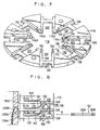
- the reversal film slide housing magazine 62 in accordance with this embodiment is constituted by a plurality of trays 116 which are piled up one upon another in such a manner as to form a hollow cylinder as a whole.
- Each of the trays 116 has the shape of a plate-like ring having a bore 118 in its center and is formed from a synthetic resin by means of molding.
- Each tray 116 has eight pockets 120 radially formed thereon, as also shown in Figs. 7 and 8.
- Each pocket 120 is designed to receive one reversal film slide 60 which is constituted by a piece of reversal film 60A retained on a frame-like mount 60B.
- the pockets 120 on each tray 116 are constituted by grooves which are formed radially thereon.
- One reversal film slide 60 is inserted into each pocket 120 in the direction of the arrow A and housed therein.
- each pocket 120 has notches 126 and 128 respectively cut therein from its inner and outer ends. These notches 126 and 128 are rectangular in plan view.
- each tray 116 has a planar configuration in which it is constituted by portions which are connected together at the pockets 120 through'cross pieces 130 each constituted by the portion of the bottom of each pocket 120 which is left between the notches 126 and 128.
- the trays 116 are piled up one upon another such as to form a multistage structure. Connecting bolts 132 are received through the piled trays 116, and top and bottom plates 134 and 136 are respectively secured to the upper and lower ends of the piled trays 116, thus forming a cylindrical shape as a whole. In an assembled state, therefore, the upper side of each of the pockets 120 on one tray 116 is closed by the bottom surface of the tray 116 which is placed thereon, thus forming a reversal film slide housing magazine 62 of a cylindrical structure with through-holes extending radially thereof.
- one end of a leaf spring 140 is secured to the bottom surface of each tray 116 by a rivet 138.
- the distal end of the leaf spring 140 presses both lateral edges of an inserted reversal film slide 60 against the bottom surface of the corresponding pocket 120, thereby preventing the slide 60 from undesirably coming out of the pocket 120.
- the top plate 134 has its axis portion rotatably supported by an upper frame plate 142.
- the bottom plate 136 has a cylindrical shaft 144 projecting axially from its inner peripheral portion and is rotatably supported by a lower frame plate 148 through a bearing 146 which is mounted on the outer periphery of the cylindrical shaft 144.
- Four supports 150 are interposed between the upper and lower frame plates 142 and 148 in such a manner as to firmly fix them to each other.
- a synthetic resin cover 152 is interposed between the upper and lower frame plates 142 and 148 such as to cover the outer periphery of the piled trays 116.
- the cover 152 has, as also shown in Fig. 9, an opening 154 formed in one portion thereof, the longitudinal axis of the opening 154 extending axially of the piled trays 116. More specifically, since in this embodiment a plurality of trays 116 are piled up such as to form a multistage structure, each of the pockets 120 allows a reversal film slide 60 to be inserted and removed in the radial direction of the piled trays 116.
- the pockets 120 are arranged such that those which are formed on the respective trays 116 constitute a multistage pocket structure which has its longitudinal axis extending axially of the piled trays 116, and eight rows of pockets 120 are therefore provided around the axis of the piled trays 116. Among the eight rows of pockets 120, only one row is permitted to communicate with the outside through the opening 154.
- the opening 154 is defined by a protuberant portion 156 of the cover 152 which projects outwardly therefrom with a gradually narrowing shape in plan view. Accordingly, even when a reversal film slide 60 is in a state wherein it has not been completely forced into a pocket 120 and a portion of the slide 60 therefore projects from the outer end of the pocket 120, this slide 60 is properly pushed into the pocket 120 when the trays 116 are rotated within the cover 152 since at that time the projecting portion of the slide 60 is pressed inwardly by the protuberant portion 156.
- the bottom plate 136 has a click groove 158 formed in a portion of its bottom surface, the click groove 158 having its longitudinal axis extending radially of the bottom plate 136.
- the click groove 158 receives the distal end portion of a click leaf spring 160 which has its proximal end secured to the lower frame plate 148.
- a pair of arms 162 are respectively secured at their central portions to two edge portions of the upper frame plate 142.
- Grip rods 164 are stretched between the arms 162 at both ends thereof, each grip rod 164 having both ends thereof secured to the arms 162.
- One of the arms 162 is formed on its outer side with a pair of power supply terminals 166 and a pair of positioning bores 168.
- the terminals 166 are used for supplying electric power to a memory device 170 which is secured to the upper surface of the upper frame plate 142 and is constituted by an IC memory or the like.
- the positioning bores 168 respectively receive positioning pins of an associated machine, thereby accurately positioning the magazine 62 relative to the machine.
- the arm 162 is provided at its central portion with upper and lower photocouplers 172 and 174. When receiving a signal from an associated machine, the photocoupler 172 sends this signal to the memory device 170, while the photocoupler 174 delivers the signal processed in the memory device 170 to the associated machine.
- the memory device 170 has stored therein data about the location of each of the slides 60, that is, information as to which slide 60 is housed in which pocket 120. In addition to the above-described data, the memory device 170 can store printing correction conditions for each reversal film 60A, the number of prints required and so forth. Construction of Magazine.Driver:
- a magazine driver 175 includes a tubular member 178 standing on the upper surface of a machine board 176.
- a feed screw 180 is rotatably supported at the axis portion of the tubular member 178 in such a manner that the longitudinal axis of the feed screw 180 extends vertically.
- a gear 182 is secured to the lower end portion of the feed screw 180, while a gear 186 is secured to the output shaft of a motor 184 which is mounted on the machine board 176, and a timing belt 188 is stretched between the gears 182 and 186.
- the feed screw 180 is rotated about its vertical axis by the rotation of the motor 184.
- the feed screw 180 has a ball screw nut 190 screwed thereon.
- the nut 190 is secured to the central portion of a support plate 192. Both end portions of the support plate 192 respectively extend through openings 194 which are formed in the tubular member 178 in such a manner that the longitudinal axis of each of the openings 194 extends longitudinally of the tubular member 178.
- the ends of the support plate 192 are then secured to a lifting board 196 through respective brackets 195.
- the lifting board 196 has the tubular member 178 extending through its central portion, one end of the lifting board 196 being secured to a lifting wall 198.
- the lifting wall 198 is adapted to be able to move vertically while being guided by a fixed wall 200 which stands on the machine board 176.
- a cylindrical wall 201 is secured to the support plate 192, and an externally toothed ring gear 204 is rotatably supported by the cylindrical wall 201 through a bearing 202.
- the ring gear 204 is meshed with a gear 208 secured to the output shaft of a motor 206 which is mounted on the support plate 192.
- a motor 206 which is mounted on the support plate 192.
- the lower end portion of a cylindrical mounting board 210 is secured to the externally toothed ring gear 204.
- the mounting board 210 extends through the area between the lifting board 196 and the tubular member 178 in such a manner that the upper end of the mounting board 210 projects upwardly beyond the lifting board 196.
- the cylindrical shaft 144 of the bottom plate 136 opposes the mounting board 210.
- the reversal film slide housing magazine 62 is mounted on the lifting wall 198.
- the cylindrical shaft 144 has a pair of engagement projections 212 and 214 projecting therefrom toward the cylindrical mounting board 210, each engagement projection having engagement slanted surfaces 216 formed at two sides thereof.
- the mounting board 210 is formed with engagement recesses 218 and 220 for respectively receiving the engagement projections 212 and 214.
- Each of the engagement recesses 218 and 220 has engagement slanted surfaces 222 which respectively abut against the engagement slanted surfaces 216.
- the engagement projection and recess 212, 218 have the same circumferential length as each other, and the engagement projection and recess 214, 220 also have the same circumferential length as each other. In this case, however, the circumferential length of the engagement projection and recess 212, 218 is shorter than that of the engagement projection and recess 214, 220. Accordingly, it is impossible for the engagement projection 214 to be inserted into the engagement recess 218.
- the reversal film slide housing magazine 62 is mounted on the cylindrical mounting board 210 only at a predetermined position in its rotation about its axis. After the magazine 62 has been mounted on the mounting board 210, the trays 116 can be rotated around the tubular member 178 by the rotation of the mounting board 210.
- the externally toothed ring gear 204 has a collar portion 205 extending radially from the upper end thereof.
- the collar portion 205 has eight pocket position detecting bores 205A formed therein in such a manner that they are spaced about the axis of the ring gear 204 such as to correspond to the eight rows of pockets 120 which are arranged about the axis of the magazine 62 when mounted on the mounting board 210.
- These pocket position detecting bores 205A can be detected by a sensor 223A which is mounted on the bottom surface of the lifting board 196.
- a loading/unloading position detecting bore 205 is formed in the collar portion 205 adjacent to one of the eight pocket position detecting bores 205A.
- the bore 205B can be detected by a sensor 223B which is disposed in parallel to the sensor 223A.
- a push-out means 224 is mounted on a top plate 223 of the tubular member 178.
- a pair of guide bars 228 are stretched between a pair of guide brackets 226 which stand on the top plate 223.
- a moving board 230 is slidably supported on the guide bars 228.
- a plate-like pusher 232 is secured to the moving board 230 in such a manner that it is possible for the pusher 232 to move together with the moving board 230.
- a rack 234 is secured to the moving board 230 and is meshed with a pinion 236 which is rotatably supported by the tubular member 178.
- the pinion 236 is rotated by means of the driving force of a motor 238, thereby allowing the moving board 230 to move along the guide bars 228.
- the pusher 232 pushes out a reversal film slide 60 which is disposed at an unloading/reloading position from the associated pocket 120, and the slide 60 thus pushed out is taken out through the opening 154 of the cover 152. More specifically, when a pocket 120 is disposed within the moving locus of the pusher 232, the slide 60 housed in this pocket 120 is placed at the unloading/reloading position. In the magazine 62, the cylindrical mounting board 210 is, as will be clear from Fig.
- a pair of optical fibers 239A and 239B are mounted on the tubular member 178 such as to face outwardly thereof and oppose each other, as shown in Fig. 8, and light is projected from the optical fiber 239A and received by the optical fiber 239B.
- the quantity of light received by the optical fiber 239B differs depending upon whether or not any of the ribs 116A which project radially from the inner end of each of the trays 116 is present within the optical path of the light projected from the optical fiber 239A. Therefore, a difference in terms of the quantity of light received by the optical fiber 239B is detected, and the height of the magazine 62 is thereby controlled.
- the rotation of the magazine 62 is suspended when the sensor 223A detects a particular pocket position detecting bore 205A, and a row of pockets which includes a desired pocket 120 is thereby disposed at the unloading/reloading position.
- the rotational position of the magazine 62 is not known at the time when the magazine driver 175 is started after the magazine 62 has been mounted on the cylindrical mounting board 210.
- the motor 206 is therefore adapted to rotate the magazine 62 until the loading/unloading position detecting bore 205B is detected by the sensor 223B.
- the moving board 230 has a striker 240 projecting therefrom in such a manner as to oppose sensors 242 and 244 which are previously mounted on the top plate 223 of the tubular member 178 at a predetermined distance.
- a striker 240 projecting therefrom in such a manner as to oppose sensors 242 and 244 which are previously mounted on the top plate 223 of the tubular member 178 at a predetermined distance.
- Fig. 12 shows a structure for securing the reversal film slide housing magazine 62 which is mounted at the upper end portion of the lifting wall 198.
- Each of parallel links 270 and 272 is pivotally supported at one end thereof by the upper end portion of the lifting wall 198 through a bracket 268.
- the respective upper end portions of the links 270 and 272 are pivotally supported by a connecting block 274, thereby allowing the connecting block 274 to come in and out of contact with the magazine 62 while maintaining its horizontal state.
- Handle levers 278 are pivotally supported through pins 276 by brackets 269, respectively, which are secured to the lifting wall 198.
- a grip rod 280 is secured to the respective distal ends of the handle levers 278, and a pin 282 is stretched between the respective intermediate portions of the handle levers 278.
- the pin 282 opposes arms 284 each projecting from one end of each of the parallel links 270.
- a tension coil spring 286 is stretched between each of the handle levers 278 and the associated bracket 269.
- the connecting block 274 By pulling and pivoting the tension coil springs 286 in such a manner that their axes respectively pass the prolongation lines of the axes of the pins 276, it is possible for the connecting block 274 to be selectively placed at two positions, that is, one in which the connecting block 274 is separated from the magazine 62 and the other in which the former is in contact with the latter. More specifically, when each of the tension coil springs 286 is disposed on one side of the prolongation line of the axis of the corresponding pin 276, the springs 286 maintain the connecting block 274 in a position which is most extreme with respect to the magazine 62.
- the connecting block 274 is provided with positioning pins 290, power supply terminals 292 and photocouplers 294, 296, which respectively correspond to those which are provided on the magazine 62.
- the apparatus body 12 has conveyor belts 380 and 382 rotatably supported by respective sprockets 384 and 386 in such a manner as to oppose the insertion opening 64.
- a reversal film slide 60 fed through the insertion opening 64 is transferred to the conveyor belts 380 and 382 and is moved by the action of the sprockets 384 which are connected to a motor (not shown).
- a pair of press rollers 388 and 390 are disposed on each of the conveyor belts 380 and 382. These press rollers 388 and 390 are rotatably supported by a lifting bracket 392 and are pressed against the respective conveyor belts 380 and 382 by means of the biasing force of tension coil springs 394 which are interposed between the lifting bracket 392 and the apparatus body 12. Thus, the slide 60 is pressed against the conveyor belts 380 and 382 so that the driving force is reliably transmitted to the slide 60 from the conveyor belts 380 and 382.
- a pivoting arm 396 is pivotally supported at its distal end portion by the lifting bracket 392.
- the proximal portion of the arm 396 is pivotally supported by a fixed bracket 402 through a pin 400. Accordingly, it is possible for the lifting bracket 392 to move vertically while maintaining its horizontal state and for the rollers 388 and 390 to individually come in and out of contact with the conveyor belts 380 and 382.
- a pivoting arm 404 is disposed on the side of the conveyor belts 380 and 382 which is remote from the magazine 62 in such a manner that the distal end portion of the arm 404 can oppose the belts 380 and 382.
- the pivoting arm 404 has a shaft 406 secured to the other end thereof as shown in Fig. 15.
- the shaft 406 is rotated by a motor 408, and it is thereby possible for the pivoting arm 404 to pivot by about 90° from the solid-line position to the imaginary-line position shown in Fig. 15.
- the pivoting arm 404 has a pair of arms 410 and 412 projecting from its distal end portion at right angles.
- the arms 410 have an L-shaped cross-section and are adapted to support a reversal film slide 60.
- a leaf spring 414 is secured to one end of each of the arms 410 and 412 by a screw 416 for the purpose of retaining a slide 60 which is inserted into the area defined between the spring 414 and each of the arms 410, 412.
- observation window 58 is closed by a shutter exclusive of the time when a slide 60 is positioned at the observation window 58 as shown by the imaginary line in Fig. 15.
- a rod 418 which serves as a reloading means is, as shown in Figs. 13 and 14, disposed above the conveyor belts 380 and 382.
- a pair of parallel links 420 and 422 are pivotally supported at their respective distal ends by the rod 418,through respective screws 424 and 426.
- the other ends of the parallel links 420 and 422 are pivotally supported by a slide block 432 through respective screws 428 and 430. Accordingly, as the parallel links 420 and 422 pivot, the rod 418 lowers while maintaining its horizontal state and can enter the moving locus of the slide 60.
- the slide block 432 is supported by a guide bar 434 and is moved in the moving direction of the slide 60. Further, a pin 421 projects from the central portion of the link 420, and an arm 437 which is driven by a rotary solenoid 436 mounted on the apparatus body 12 abuts against the pin 421.
- the slide block 432 is moved toward the magazine 62.
- Reversal film slides 60 which have already been subjected to printing are respectively housed in the pockets 120 of the reversal film slide housing magazine 62 in accordance with the order in which they have been printed.
- This magazine 62 is mounted on the rear of the reversal film inspecting apparatus 10.
- a roll of photographic paper 22 which has already been subjected to printing is mounted on the takeup shaft 14 of the inspecting apparatus 10, and the leading end portion of the photographic paper 22 is retained by the takeup shaft 16.
- the photographic paper 22 is wound up onto the takeup shaft 16 at an appropriate speed, and while doing so, the operator inspects the printed state of each of the frames 22A on the photographic paper 22 which passes along the print paper inspection board 24.
- the perforations 34 and 36 are respectively detected by the sensors 30 and 32 as the photographic paper 22 moves on the inspection board 24. Accordingly, the frames 22A passing along the inspection board 24 can be identified at any time in the inspecting operation in terms of which frame 22A corresponds to which reversal film slide 60 in the magazine 62.
- the operator inputs printing conditions which are required to effect re-printing by actuating the input buttons 56 and thereby stores the printing conditions in the memory device 170.
- the pocket 120 housing the reversal film slide 60 which corresponds to the frame 22A formed with the check or NG mark 42 is retrieved and moved such as to oppose the insertion opening 64 by the action of the lifting board 196 which is moved vertically and that of the cylindrical mounting board 110 which is rotated by the motor 106.
- the slide 60 is then pushed out toward the insertion opening 64 by the action of the pusher 232.
- the conveyor belts 380 and 382 are actuated to move in such a manner as to receive the slide 60 as well as feed the same to the arms 410 and 412 and cause the slide 60 to be retained by the leaf springs 414.
- the pivoting arm 404 is moved from the solid-line position to the imaginary-line position in Fig. 15 by driving the motor 408 in such a manner that the distal end portion of the arm 404 is disposed at the observation window 58.
- the slide 60 is turned by 90 0 , which fact makes it possible for the operator to observe and check the picture on the slide 60 in its natural or correctly placed position and hence to input accurate printing conditions for a re-printing operation and store them in the memory device 170.
- the pivoting arm 404 is pivoted by 90° to return to the solid-line position in Fig. 15, and the central portion of the slide 60 is retained by the conveyor belts 380 and 382.
- the slide 60 is then moved toward the insertion opening 64 by means of the driving force of the conveyor belts 380 and 382.
- the rod 418 is lowered by means of the driving force of the rotary solenoid 436 in such a manner as to oppose the rear of the slide 60, and the slide 60 is then reloaded into the associated pocket 120 of the magazine 62 by the movement of the rod 418.
- Fig. 17 shows the arrangement in which a reversal film slide housing magazine 62 is connected to an input machine 500.
- the magazine 62 is connected to the input machine 500 through a magazine driver 175 in a manner similar to that in the case of the above-described inspecting apparatus.
- This arrangement is similar to that which has already been described in that it is possible for any desired pocket 120 to be aligned with an unloading/reloading position which is coaxial with a conveying path 502 of the input machine 500.
- the input machine 500 is arranged such that a plurality of slides 60 are disposed on an illuminator 504, and the operator provides a visual check for each of the slides 60 to judge the printed state of the picture on each slide 60 and records printing conditions required to re-print any slide 60 which carries an improperly printed picture into the memory device 170 mounted in the associated magazine 62 by the use of operating buttons 506.
- Those of the slides 60 which have already had their re-printing conditions input are passed through an obverse/reverse judging means 508 which is disposed at an intermediate portion of the slide conveying path 502 and are successively reloaded into respective pockets 120 of the magazine 62, data on their respective housed positions being stored in the memory device 170.
- Fig. 18 shows the arrangement in which a reversal film slide housing magazine 62 which has already been subjected to the processing carried out in the input machine 500 shown in Fig. 17 is mounted on the supply side of a printer 510 through a magazine driver 175.
- a similar magazine 62 is disposed on a magazine driver 175 on the reception side of the printer 510 which is opposite to the supply side thereof. In this state, the magazine 62 on the reception side is empty, that is, no slide 60 has yet been housed therein.
- reversal film slides 60 in the respective pockets 120 are successively fed to a printing board 514 through a conveying path 512.
- the slides 60 After the slides 60 have been printed on a roll of photographic paper 22, the slides 60 are successively housed in the magazine 62 on the reception side through a conveying path 516.
- each of the conveying paths 512 and 516 is provided at one end thereof with an unloading means which is similar to the conveyor belts 382, 384 and a reloading means which pushes a slide 60 into a pocket 120.
- a reversal film slide housing magazine 62 which has already been subjected to the processing carried out in the reversal film inspecting apparatus 10 is connected to a checking machine 518 through a magazine driver 175 in a manner similar to the above.
- the checking machine 518 as the final process, the reversal film slides 60 are successively pushed out of the respective pockets 120 and are fed out by means of a conveyor 520 and then deposited on a conveyor 524 through a mounting board 522.
- a sorting card 60C which is disposed at the top of a series of slides 60 ordered by an individual customer is pushed out by a pusher 526 in a direction orthogonal to the slide discharging direction when it is discharged onto the mounting board 522, the sorting card 60C thus being housed in a stock casing 528.
- the slides 60 which are deposited on the conveyor 524 are piled up in series for each of the orders placed by individual customers and are checked against corresponding sheets of photographic paper which have been cut into individual picture frames by a cutting machine (not shown) before being put into respective bags.
- a magazine 62 containing any slide 60 which needs to be re-printed is returned to the printer 510, and after a re-printing operation, the magazine 62 is sent to the inspecting apparatus 10 again and is then transported to the checking machine 518.
- the inspecting apparatus 10 the input machine 500, the printer 510 and the checking machine 518 are previously provided with the respective magazine drivers 175, and a magazine 62 alone is successively mounted on these magazine drivers 175 so as to move reversal film slides 60.
- the arrangement may be such that the magazine 62 is moved together with a magazine driver 175.
Landscapes
- Physics & Mathematics (AREA)
- General Physics & Mathematics (AREA)
- Projection-Type Copiers In General (AREA)
Applications Claiming Priority (8)
| Application Number | Priority Date | Filing Date | Title |
|---|---|---|---|
| JP163606/84 | 1984-08-03 | ||
| JP12018284U JPS6136846U (ja) | 1984-08-03 | 1984-08-03 | プリントペ−パ−検査装置 |
| JP120181/84 | 1984-08-03 | ||
| JP163607/84 | 1984-08-03 | ||
| JP59163607A JPH0672998B2 (ja) | 1984-08-03 | 1984-08-03 | リバ−サルスライド収納マガジン |
| JP120182/84 | 1984-08-03 | ||
| JP16360684A JPS6142639A (ja) | 1984-08-03 | 1984-08-03 | リバ−サルスライド収納マガジン駆動装置 |
| JP12018184U JPS6136845U (ja) | 1984-08-03 | 1984-08-03 | リバ−サルフイルム検査装置 |
Publications (3)
| Publication Number | Publication Date |
|---|---|
| EP0171029A2 true EP0171029A2 (de) | 1986-02-12 |
| EP0171029A3 EP0171029A3 (en) | 1986-08-27 |
| EP0171029B1 EP0171029B1 (de) | 1989-09-27 |
Family
ID=27470661
Family Applications (1)
| Application Number | Title | Priority Date | Filing Date |
|---|---|---|---|
| EP19850109598 Expired EP0171029B1 (de) | 1984-08-03 | 1985-07-30 | Gerät zur Kontrolle von Umkehrfilmen |
Country Status (2)
| Country | Link |
|---|---|
| EP (1) | EP0171029B1 (de) |
| DE (1) | DE3573322D1 (de) |
Cited By (1)
| Publication number | Priority date | Publication date | Assignee | Title |
|---|---|---|---|---|
| FR2798746A1 (fr) * | 1999-04-15 | 2001-03-23 | Cewe Color Ag & Co Ohg | Dispositif pour enrouler et derouler des rouleaux de bandes de papier photo |
Citations (8)
| Publication number | Priority date | Publication date | Assignee | Title |
|---|---|---|---|---|
| DE1181043B (de) * | 1963-07-11 | 1964-11-05 | Agfa Ag | Transporteinrichtung fuer gerahmte Diapositive fuer Kopiergeraete |
| DE1772458A1 (de) * | 1967-05-31 | 1971-04-08 | Ciba Geigy | Einrichtung zum automatischen Kopieren von Farbphotonegativen auf Positivpapier,ausgeruestet mit einem Printer und einem Betrachtertisch |
| DE1772513A1 (de) * | 1968-05-28 | 1971-04-22 | Photo Color Studio H Bircher & | Verfahren zum Kopieren oder Vergroessern von Diapositiven |
| US3768905A (en) * | 1972-03-15 | 1973-10-30 | Eastman Kodak Co | Method and apparatus for inspection of photographic prints |
| DE2438913A1 (de) * | 1974-08-09 | 1976-02-19 | Heinz Seiler | Projektionsgeraet mit vorratsmagazinwechselvorrichtung fuer scheibenfoermige bildtraeger |
| US4021114A (en) * | 1976-01-26 | 1977-05-03 | Lure Camera Ltd. | Film strip controller |
| EP0008557A2 (de) * | 1978-08-17 | 1980-03-05 | EASTMAN KODAK COMPANY (a New Jersey corporation) | Fotografisches Farbkopiergerät und Verfahren zur Bestimmung der Belichtungszeiten |
| DE3424799A1 (de) * | 1983-07-07 | 1985-01-17 | Fuji Photo Film Co., Ltd., Minami-Ashigara, Kanagawa | Diamagazin mit einer speichereinrichtung fuer ein diafilm-abziehsystem |
-
1985
- 1985-07-30 EP EP19850109598 patent/EP0171029B1/de not_active Expired
- 1985-07-30 DE DE8585109598T patent/DE3573322D1/de not_active Expired
Patent Citations (8)
| Publication number | Priority date | Publication date | Assignee | Title |
|---|---|---|---|---|
| DE1181043B (de) * | 1963-07-11 | 1964-11-05 | Agfa Ag | Transporteinrichtung fuer gerahmte Diapositive fuer Kopiergeraete |
| DE1772458A1 (de) * | 1967-05-31 | 1971-04-08 | Ciba Geigy | Einrichtung zum automatischen Kopieren von Farbphotonegativen auf Positivpapier,ausgeruestet mit einem Printer und einem Betrachtertisch |
| DE1772513A1 (de) * | 1968-05-28 | 1971-04-22 | Photo Color Studio H Bircher & | Verfahren zum Kopieren oder Vergroessern von Diapositiven |
| US3768905A (en) * | 1972-03-15 | 1973-10-30 | Eastman Kodak Co | Method and apparatus for inspection of photographic prints |
| DE2438913A1 (de) * | 1974-08-09 | 1976-02-19 | Heinz Seiler | Projektionsgeraet mit vorratsmagazinwechselvorrichtung fuer scheibenfoermige bildtraeger |
| US4021114A (en) * | 1976-01-26 | 1977-05-03 | Lure Camera Ltd. | Film strip controller |
| EP0008557A2 (de) * | 1978-08-17 | 1980-03-05 | EASTMAN KODAK COMPANY (a New Jersey corporation) | Fotografisches Farbkopiergerät und Verfahren zur Bestimmung der Belichtungszeiten |
| DE3424799A1 (de) * | 1983-07-07 | 1985-01-17 | Fuji Photo Film Co., Ltd., Minami-Ashigara, Kanagawa | Diamagazin mit einer speichereinrichtung fuer ein diafilm-abziehsystem |
Cited By (1)
| Publication number | Priority date | Publication date | Assignee | Title |
|---|---|---|---|---|
| FR2798746A1 (fr) * | 1999-04-15 | 2001-03-23 | Cewe Color Ag & Co Ohg | Dispositif pour enrouler et derouler des rouleaux de bandes de papier photo |
Also Published As
| Publication number | Publication date |
|---|---|
| DE3573322D1 (en) | 1989-11-02 |
| EP0171029B1 (de) | 1989-09-27 |
| EP0171029A3 (en) | 1986-08-27 |
Similar Documents
| Publication | Publication Date | Title |
|---|---|---|
| US7536938B2 (en) | Apparatus for cutting series of medicine packets | |
| EP0171029B1 (de) | Gerät zur Kontrolle von Umkehrfilmen | |
| EP1000701A2 (de) | Vorrichtung zum Erkennen und Ausrichten der Orientierung wiederverwendbarer Kameras | |
| US6018356A (en) | Printing apparatus and autocharger thereof | |
| EP0173097B1 (de) | Fotografisches Kopiersystem | |
| JPS6142639A (ja) | リバ−サルスライド収納マガジン駆動装置 | |
| JPH0672998B2 (ja) | リバ−サルスライド収納マガジン | |
| JPS63311253A (ja) | 仕上り印画検定装置 | |
| US5154409A (en) | Film storage device | |
| US6965425B2 (en) | Supplying apparatus for recording material | |
| US5218186A (en) | Film storage device | |
| JP2959168B2 (ja) | 絵柄面積率測定システム | |
| JP2724255B2 (ja) | 写真処理装置用パトローネ収納容器 | |
| EP1251393B1 (de) | Diarahmen-Trägereinheit und Film Scanner | |
| JP2006112972A (ja) | 測色装置、及びこれを備えた写真処理装置 | |
| JPH043732A (ja) | 原稿カセット供給装置 | |
| JPH0210530Y2 (de) | ||
| JP2959167B2 (ja) | 絵柄面積率測定システム | |
| JP2719461B2 (ja) | プリント集積装置及びプリント集積方法 | |
| JP2697324B2 (ja) | X線撮影装置 | |
| US7083339B2 (en) | Magazine shuttle for a photographic processor | |
| JP2702005B2 (ja) | 写真プリントの搬送方法 | |
| JP2511525B2 (ja) | フイルム送り装置 | |
| JP3606193B2 (ja) | マウントキャリアユニットおよびフィルムスキャナ | |
| JP2910294B2 (ja) | 絵柄面積率測定システム |
Legal Events
| Date | Code | Title | Description |
|---|---|---|---|
| PUAI | Public reference made under article 153(3) epc to a published international application that has entered the european phase |
Free format text: ORIGINAL CODE: 0009012 |
|
| AK | Designated contracting states |
Designated state(s): CH DE LI |
|
| PUAL | Search report despatched |
Free format text: ORIGINAL CODE: 0009013 |
|
| AK | Designated contracting states |
Kind code of ref document: A3 Designated state(s): CH DE LI |
|
| 17P | Request for examination filed |
Effective date: 19860909 |
|
| 17Q | First examination report despatched |
Effective date: 19880223 |
|
| GRAA | (expected) grant |
Free format text: ORIGINAL CODE: 0009210 |
|
| AK | Designated contracting states |
Kind code of ref document: B1 Designated state(s): CH DE LI |
|
| REF | Corresponds to: |
Ref document number: 3573322 Country of ref document: DE Date of ref document: 19891102 |
|
| PLBE | No opposition filed within time limit |
Free format text: ORIGINAL CODE: 0009261 |
|
| STAA | Information on the status of an ep patent application or granted ep patent |
Free format text: STATUS: NO OPPOSITION FILED WITHIN TIME LIMIT |
|
| 26N | No opposition filed | ||
| PGFP | Annual fee paid to national office [announced via postgrant information from national office to epo] |
Ref country code: DE Payment date: 20020919 Year of fee payment: 18 |
|
| PGFP | Annual fee paid to national office [announced via postgrant information from national office to epo] |
Ref country code: CH Payment date: 20021011 Year of fee payment: 18 |
|
| PG25 | Lapsed in a contracting state [announced via postgrant information from national office to epo] |
Ref country code: LI Free format text: LAPSE BECAUSE OF NON-PAYMENT OF DUE FEES Effective date: 20030731 Ref country code: CH Free format text: LAPSE BECAUSE OF NON-PAYMENT OF DUE FEES Effective date: 20030731 |
|
| PG25 | Lapsed in a contracting state [announced via postgrant information from national office to epo] |
Ref country code: DE Free format text: LAPSE BECAUSE OF NON-PAYMENT OF DUE FEES Effective date: 20040203 |
|
| REG | Reference to a national code |
Ref country code: CH Ref legal event code: PL |