EP0169661A2 - Vorrichtung zum Wiederherstellen von Ketten - Google Patents
Vorrichtung zum Wiederherstellen von Ketten Download PDFInfo
- Publication number
- EP0169661A2 EP0169661A2 EP85304399A EP85304399A EP0169661A2 EP 0169661 A2 EP0169661 A2 EP 0169661A2 EP 85304399 A EP85304399 A EP 85304399A EP 85304399 A EP85304399 A EP 85304399A EP 0169661 A2 EP0169661 A2 EP 0169661A2
- Authority
- EP
- European Patent Office
- Prior art keywords
- shoe
- holding member
- lug
- grouser
- welding
- Prior art date
- Legal status (The legal status is an assumption and is not a legal conclusion. Google has not performed a legal analysis and makes no representation as to the accuracy of the status listed.)
- Granted
Links
- 238000003466 welding Methods 0.000 claims abstract description 61
- 230000007246 mechanism Effects 0.000 claims description 10
- 125000006850 spacer group Chemical group 0.000 claims description 8
- 238000005096 rolling process Methods 0.000 claims description 2
- 238000005520 cutting process Methods 0.000 description 11
- 238000010276 construction Methods 0.000 description 3
- 230000001012 protector Effects 0.000 description 3
- 230000004907 flux Effects 0.000 description 2
- 230000003247 decreasing effect Effects 0.000 description 1
- 230000000881 depressing effect Effects 0.000 description 1
- 230000000694 effects Effects 0.000 description 1
- 230000006872 improvement Effects 0.000 description 1
- 238000009434 installation Methods 0.000 description 1
- 230000007257 malfunction Effects 0.000 description 1
- 239000002184 metal Substances 0.000 description 1
- 230000009467 reduction Effects 0.000 description 1
- 238000005493 welding type Methods 0.000 description 1
Images


Classifications
-
- B—PERFORMING OPERATIONS; TRANSPORTING
- B23—MACHINE TOOLS; METAL-WORKING NOT OTHERWISE PROVIDED FOR
- B23K—SOLDERING OR UNSOLDERING; WELDING; CLADDING OR PLATING BY SOLDERING OR WELDING; CUTTING BY APPLYING HEAT LOCALLY, e.g. FLAME CUTTING; WORKING BY LASER BEAM
- B23K37/00—Auxiliary devices or processes, not specially adapted to a procedure covered by only one of the preceding main groups
- B23K37/04—Auxiliary devices or processes, not specially adapted to a procedure covered by only one of the preceding main groups for holding or positioning work
- B23K37/0461—Welding tables
-
- B—PERFORMING OPERATIONS; TRANSPORTING
- B23—MACHINE TOOLS; METAL-WORKING NOT OTHERWISE PROVIDED FOR
- B23P—METAL-WORKING NOT OTHERWISE PROVIDED FOR; COMBINED OPERATIONS; UNIVERSAL MACHINE TOOLS
- B23P6/00—Restoring or reconditioning objects
-
- B—PERFORMING OPERATIONS; TRANSPORTING
- B23—MACHINE TOOLS; METAL-WORKING NOT OTHERWISE PROVIDED FOR
- B23K—SOLDERING OR UNSOLDERING; WELDING; CLADDING OR PLATING BY SOLDERING OR WELDING; CUTTING BY APPLYING HEAT LOCALLY, e.g. FLAME CUTTING; WORKING BY LASER BEAM
- B23K37/00—Auxiliary devices or processes, not specially adapted to a procedure covered by only one of the preceding main groups
- B23K37/02—Carriages for supporting the welding or cutting element
- B23K37/0211—Carriages for supporting the welding or cutting element travelling on a guide member, e.g. rail, track
-
- B—PERFORMING OPERATIONS; TRANSPORTING
- B23—MACHINE TOOLS; METAL-WORKING NOT OTHERWISE PROVIDED FOR
- B23K—SOLDERING OR UNSOLDERING; WELDING; CLADDING OR PLATING BY SOLDERING OR WELDING; CUTTING BY APPLYING HEAT LOCALLY, e.g. FLAME CUTTING; WORKING BY LASER BEAM
- B23K37/00—Auxiliary devices or processes, not specially adapted to a procedure covered by only one of the preceding main groups
- B23K37/02—Carriages for supporting the welding or cutting element
- B23K37/0294—Transport carriages or vehicles
-
- B—PERFORMING OPERATIONS; TRANSPORTING
- B23—MACHINE TOOLS; METAL-WORKING NOT OTHERWISE PROVIDED FOR
- B23K—SOLDERING OR UNSOLDERING; WELDING; CLADDING OR PLATING BY SOLDERING OR WELDING; CUTTING BY APPLYING HEAT LOCALLY, e.g. FLAME CUTTING; WORKING BY LASER BEAM
- B23K37/00—Auxiliary devices or processes, not specially adapted to a procedure covered by only one of the preceding main groups
- B23K37/04—Auxiliary devices or processes, not specially adapted to a procedure covered by only one of the preceding main groups for holding or positioning work
Definitions
- the present invention relates to an apparatus for rebuilding worn track shoe for a line of track chain usable for construction machine or the like and more particularly to improvement of or relating to an apparatus for rebuilding worn shoe by welding operation, werein an assembly of shoe and replacement lug is caused to turn upside down after completion of welding operation over the one welding area while they are brought in firm contact with one another.
- shoe mounted on a line of track chain for construction machine such as bulldozer or the like has a grouser projected outwardly of the surface and the grouser tends to wear increasingly as construction machine continues to operate.
- a high intensity of tracting force fails to be generated due to reduced depth of driving of the grouser into the ground, resulting in decreased capability of excavating and degraded operational efficiency.
- worn shoe should be repaired or rebuilt when the extent of wearing reached a predetermined level during running operation. Rebuilding of worn shoe is usually carried out by way of the steps of cutting off the worn part of grouser, fitting replacement lug having a certain height to the latter and then butt welding an assembly of replacement lug and grouser along the welding area.
- the present invention has been made with the foregoing background in mind and its object resides in providing an improved apparatus for rebuilding worn shoe by welding operation without any necessity for dismounting an assembly of shoe and replacement lug after completion of welding over the welding area on the one side.
- an apparatus for rebuilding worn shoe grouser for a line of track chain by welding operation essentially comprising a lug holding member having a groove formed thereon so as to allow a replacement lug to be fitted into the groove, the lug holding member including a rotary shaft extending at- a right angle relative to the groove on the opposite side to the latter, a shoe holding member located opposite to the groove of the lug holding member, the center line of the shoe holding member being held in alignment with the axis of the rotary shaft of the lug holding member, a shoe supporting member made integral with the shoe holding member, a thrusting mechanism for displacing the shoe holding member forward and backward along the axis of the rotary shaft, and a turning mechanism for turning an assembly of thrusting mechanism, shoe supporting member, shoe holding member, shoe grouser, replacement lug and lug holding member so that shoe grouser and replacement lug are turned upside down after completion of welding operation over the welding area on the one side while they are brought in firm contact with
- the lug holding member, the shoe holding member and the thrusting mechanism are arranged on the same axis of rotary shafts in the symmetrical relation whereby the whole assembly is easy to be turned upside down by rotating a handle.
- each of the spacers has a groove formed on the one side so as to allow a replacement lug to be fitted thereto, while it includes a shoe thrusting member on the other side.
- arrangement is made such that a single welder head is disposed to move along rail which extends through a plurality of apparatuses so that the latter are operated merely by using a single welder head.
- the apparatus is preferably provided with moving means such as caster or the like rolling means so that it is movable relative to a welding machine.
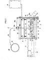
- the apparatus of the invention as identified by reference letter A includes a housing 1 which is provided with traverse frames la and 1b and moving wheels 2 such as caster or the like means.
- the apparatus A is movable relative to a welding machine B as identified by chain lines in FIGS. 1 and- 2.
- a grouser cutting device C is attached to the frame 1 of the apparatus A, as illustrated by chain lines in FIGS. 1 and 2.
- a lug holding member 4 is arranged on the fore traverse frame la to turn about the rotary shaft 3 and a groove 5 for holding a lug 32 while fitting the outer edge 32a thereto is formed on the rear side 4a of the lug holding member 4.
- reference numeral 6 designates a mounting member for replaceably mounting the lug holding member 4, reference numeral 6a does a fastening bolt, reference numeral 6b does a mounting head made integral with the shaft 3 and reference numeral 6c does a mounting bar through which the shaft 3 extends and reference numeral 6d does a mounting sleeve which is fitted through the center hole 7 on the traverse frame la.
- the sleeve 6d serves to rotatably hold the rotary shaft 3.
- reference numeral 8 designates a set screw for preventing the rotary shaft 3 from being disconnected from the sleeve 6d.
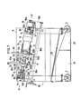
- Reference numeral 9 designates a shoe holding member which is secured to the foremost end of the piston rod 12a of the hydraulic cylinder 12 firmly assembled with the rotary shaft 11 which is rotatably inserted through a center hole 10 on the rear traverse frame lb.
- the center hole 10 is located on the extension line extending from the axis of the rotary shaft 3.
- the lug holding member 4, the shoe holding member 9 and the cylinder 12 are arranged on the same axis X - X' of the rotary shafts 3 and 11 in the symmetrical relation.
- Reference numeral 13 designates a shoe supporting member fixedly attached to the guide bar 14 of the shoe holding member 9.
- the guide bar 14 is secured to the shoe holding member 9 so that it moves in the direction of the axis X - X' of the rotary shafts 3 and 11 while it is carried by means of connecting rods 16 which serve to operatively connect the mounting bar 6c of the lug holding member 4 to the bar 15 which is integrally assembled with the rotary shaft 11 and the hydraulic cylinder 12.
- the connecting rods 16 serves also for guiding movement of the bar 15.
- the bars 6c, 14 and 15 are turned together with the connecting rods 16 about the rotary shafts 3 and 11.
- a rotary frame .17 is constituted by these members in the symmetrical relation relative to the axis X - X'.
- the rotary shaft 11 of the shoe holding member 9 is caused to rotate by means of a combination of handle 18, handle shaft 18a, endless chain 18b and shafts 19a and 19b in the speed reduction mechanism 19.
- Reference numeral 20 designates a spilling protector adapted to abut against both the ends of the welding area 33 as defined between the grouser 31 and the replacement lug 32.
- the protector 20 serves to inhibit molten metal from spilling over both the ends of the welding area 33 and it is carried on the uppermost end of a flexible arm 21 which extends upwardly of the magnet 22 on the housing 1.
- Reference numeral 23 designates a flux screen located at the lower part of the housing 1. The screen 23 serves to separate flux F into finer portion 24 and coarser portion 25 after completion of welding operation.
- Reference numeral 26 designates a welder head movable on the rail 26a of the welding machine B in the transverse direction and reference numeral 27 does a gas cutter in the grouser cutting device C for cutting off the worn part of the grouser 31.
- the gas cutter 27 is adapted to carry out cutting operation while following the configuration of the rear surface 30b of the shoe 30.
- Reference numeral 28 designates a welding rod which is fed to the welder head 26 through the guide 29.
- the rotary shafts 3 and 11 are inclined so that the tapered face in the welding area 33 assumes the horizontal posture. It should of cource be understood that the present invention should not be limited only to this but they may be laid in the horizontal direction.
- Grouser 31 wears in the different way from shoe to shoe. Therefore, there are previously provided several kinds of replacement lugs 32 having different height, for instance, 1", 11" or the like. Worn grouser 3 1 is first cut by means of the gas cutter 27 at the position L which is determined in consideration of the height of the replacement lug 32, as schematically illustrated in FIGS. 5A and 5B so that each grouser has the same height after completion of rebuilding. Then, the welding end face 32b of the replacement lug 32 is placed on the cut end face 31a (welding end face) of the grouser 31 under the effect of depressing force and thereafter welding operation is initiated (see FIG. 5C).
- the outer edge 32a of the replacement lug Prior to welding operation the outer edge 32a of the replacement lug is firmly fitted to the groove 5 of the lug holding member 4 and the end part 30a of the worn shoe 30 is supported on the shoe supporting member 13 while the welding end face 32b of the replacement lug 32 is located opposite to the welding end face 31a of the grouser _31 with the welder head 26 disposed above the welding area 33, as illustrated in FIG. 3.
- the hydraulic cylinder 12 is actuated and thereby the piston rod 12a moves forwardly until the shoe holding member 9 abuts against the rear surface 30b of the shoe 30 and the welding end face 3 1 e of the latter comes in firm contact with the welding end face 32b of the replacement lug 32.
- the shoe 30 is deformed to the configuration as illustrated in FIG. 6 under the influence of heat at an elevated temperature during cutting operation but this deformation is practically removed by thrusting operation of the piston rod 12a of the hydraulic cylinder 12.
- the one welding area 33 is ready to be worked by means of the welding head 26 while the spilling protectors 20 are sealably engaged to both the side ends of the welding area 33 (see FIG. 4).
- the welder head 26 After completion of welding operation over the one welding area the welder head 26 is retracted sideways from the operative position and the handle 18 is then rotated so that the assembly of lug, grouser and others is turned upside down.
- the other welding area located reverse to the first mentioned one is subjected to welding operation by means of the welder head 26 while the grouser 31 and the lug 32 are firmly clamped between the shoe holding member 9 and the lug holding member 4.
- the apparatus of the invention has the following advantageous features. Since the apparatus is constructed such that both welding areas on the assembly of grouser and lug are welded while they are brought in firm contact with one another, it is assured that deformation caused during cutting operation of shoe is removed to the straight configuration and thereby rebuilt shoe has the substantially same beautiful appearance as that of new one. Further, since welding operation is carried out at the same positional level over both the welding areas by rotating handle about the rotary shafts which extend at a right angle relative to the welding areas, there is no necessity for dismounting and remounting of grouser and lug after completion of welding operation over the one welding area and moreover there is no necessity for readjusting of their position after they are turned upside down. As a result, welding operation can be carried out at an operational efficiency remarkably higher than that in case of conventional apparatus.
- the apparatus is provided with a spacer 34 of which one side has a groove 35 for receiving lug therein and of which other side includes a shoe thrusting member 36.
- the spacer 34 serves also as shoe holding member.
- the spacer 34 is located between the grouser 31 of the fore shoe 30 and the replacement lug 32 of the rear shoe 30 in alignment with the rotary shafts 3 and 11 whereby welding operation is simultaneously carried out.for two worn shoes on the same apparatus. As a result, welding operation can be achieved at- an increased operational efficiency.
- two shoes are mounted on the apparatus for rebuilting work. Alternatively, more than two shoes may be mounted thereon for the same purpose.
- the apparatus A of the invention is installed separate from the welding machine B. Owing to this type of installation made in this way any other type of welding machine such as link welder, roller welder or the like each of which is installed for assembling a line of track chain at the position located on an extension line extending from the apparatus may be employed.
- any other type of welding machine such as link welder, roller welder or the like each of which is installed for assembling a line of track chain at the position located on an extension line extending from the apparatus may be employed.
- Another advantageous feature of the invention is that both cutting and welding operations can be simultaneously carried out when the apparatus A and the grouser cutting device C are arranged side by side.
Landscapes
- Engineering & Computer Science (AREA)
- Mechanical Engineering (AREA)
- Physics & Mathematics (AREA)
- Optics & Photonics (AREA)
- Machines For Laying And Maintaining Railways (AREA)
- Butt Welding And Welding Of Specific Article (AREA)
- Automatic Assembly (AREA)
Applications Claiming Priority (2)
| Application Number | Priority Date | Filing Date | Title |
|---|---|---|---|
| JP59127588A JPS617074A (ja) | 1984-06-22 | 1984-06-22 | シユ−グロ−サの矯正両面溶接修復装置 |
| JP127588/84 | 1984-06-22 |
Publications (3)
| Publication Number | Publication Date |
|---|---|
| EP0169661A2 true EP0169661A2 (de) | 1986-01-29 |
| EP0169661A3 EP0169661A3 (en) | 1988-01-07 |
| EP0169661B1 EP0169661B1 (de) | 1989-10-11 |
Family
ID=14963783
Family Applications (1)
| Application Number | Title | Priority Date | Filing Date |
|---|---|---|---|
| EP85304399A Expired EP0169661B1 (de) | 1984-06-22 | 1985-06-20 | Vorrichtung zum Wiederherstellen von Ketten |
Country Status (6)
| Country | Link |
|---|---|
| US (1) | US4622451A (de) |
| EP (1) | EP0169661B1 (de) |
| JP (1) | JPS617074A (de) |
| KR (1) | KR900000800B1 (de) |
| CA (1) | CA1250134A (de) |
| DE (1) | DE3573553D1 (de) |
Families Citing this family (7)
| Publication number | Priority date | Publication date | Assignee | Title |
|---|---|---|---|---|
| US6276056B1 (en) * | 1997-12-19 | 2001-08-21 | Ford Global Technologies, Inc. | Method for modifying a torque converter hub |
| JP4451340B2 (ja) * | 2005-03-25 | 2010-04-14 | カヤバ工業株式会社 | 溶接装置 |
| US20100016657A1 (en) * | 2006-04-24 | 2010-01-21 | Continence Control Systems International Pty Ltd | Method and Apparatus for Managing Erectile Dysfunction |
| US7858897B2 (en) | 2006-10-27 | 2010-12-28 | United Technologies Corporation | Insert weld repair |
| CN108526796B (zh) * | 2018-06-25 | 2019-08-06 | 安徽江淮汽车集团股份有限公司 | 一种后吊耳板总成焊接工装 |
| CN110744248B (zh) * | 2019-10-21 | 2021-12-14 | 内蒙古工业大学 | 一种履带链板牙条修复焊接装置 |
| CN111571051B (zh) * | 2020-05-06 | 2022-04-01 | 徐州徐工基础工程机械有限公司 | 一种旋挖钻钻杆外键焊前预热和焊后热处理系统及方法 |
Citations (6)
| Publication number | Priority date | Publication date | Assignee | Title |
|---|---|---|---|---|
| US2227688A (en) * | 1938-12-19 | 1941-01-07 | Goodman Mfg Co | Welding fixture |
| US3230616A (en) * | 1964-01-13 | 1966-01-25 | L & B Welding Equipment Inc | Method of welding replacement elements such as grouser bars, drive sprocket rims, and replacement element therefor |
| GB1290740A (de) * | 1970-04-23 | 1972-09-27 | ||
| SU507419A1 (ru) * | 1974-10-01 | 1976-03-25 | Специальное Конструкторское Бюро Скб Мосстрой | Поточна лини дл производства сварных изделий |
| JPS57209476A (en) * | 1981-06-17 | 1982-12-22 | Caterpillar Mitsubishi Ltd | Repairing device of lug part of infinite orbital shoe |
| JPS58126267A (ja) * | 1982-01-19 | 1983-07-27 | Caterpillar Mitsubishi Ltd | 履帯式車輛のシユ−のグロ−サ再生装置 |
Family Cites Families (3)
| Publication number | Priority date | Publication date | Assignee | Title |
|---|---|---|---|---|
| DE210858C (de) * | ||||
| US2927992A (en) * | 1958-06-23 | 1960-03-08 | Bateman William Henry | Automatic electric arc welding |
| JPS514271Y2 (de) * | 1972-12-21 | 1976-02-06 |
-
1984
- 1984-06-22 JP JP59127588A patent/JPS617074A/ja active Granted
-
1985
- 1985-02-07 US US06/698,934 patent/US4622451A/en not_active Expired - Lifetime
- 1985-02-18 CA CA000474556A patent/CA1250134A/en not_active Expired
- 1985-03-06 KR KR1019850001432A patent/KR900000800B1/ko not_active IP Right Cessation
- 1985-06-20 EP EP85304399A patent/EP0169661B1/de not_active Expired
- 1985-06-20 DE DE8585304399T patent/DE3573553D1/de not_active Expired
Patent Citations (6)
| Publication number | Priority date | Publication date | Assignee | Title |
|---|---|---|---|---|
| US2227688A (en) * | 1938-12-19 | 1941-01-07 | Goodman Mfg Co | Welding fixture |
| US3230616A (en) * | 1964-01-13 | 1966-01-25 | L & B Welding Equipment Inc | Method of welding replacement elements such as grouser bars, drive sprocket rims, and replacement element therefor |
| GB1290740A (de) * | 1970-04-23 | 1972-09-27 | ||
| SU507419A1 (ru) * | 1974-10-01 | 1976-03-25 | Специальное Конструкторское Бюро Скб Мосстрой | Поточна лини дл производства сварных изделий |
| JPS57209476A (en) * | 1981-06-17 | 1982-12-22 | Caterpillar Mitsubishi Ltd | Repairing device of lug part of infinite orbital shoe |
| JPS58126267A (ja) * | 1982-01-19 | 1983-07-27 | Caterpillar Mitsubishi Ltd | 履帯式車輛のシユ−のグロ−サ再生装置 |
Non-Patent Citations (2)
| Title |
|---|
| PATENT ABSTRACTS OF JAPAN, vol. 7, no. 237 (M-250)[1382], 21st October 1983; & JP-A-58 126 267 (KIYATAPIRAA MITSUBISHI K.K.) 27-07-1983 * |
| PATENT ABSTRACTS OF JAPAN, vol. 7, no. 68 (M-201)[1213], 19th March 1983; & JP-A-57 209 476 (KIYATAPIRAA MITSUBISHI K.K.) 22-12-1982 * |
Also Published As
| Publication number | Publication date |
|---|---|
| EP0169661A3 (en) | 1988-01-07 |
| CA1250134A (en) | 1989-02-21 |
| KR900000800B1 (ko) | 1990-02-17 |
| DE3573553D1 (en) | 1989-11-16 |
| EP0169661B1 (de) | 1989-10-11 |
| KR860000119A (ko) | 1986-01-25 |
| US4622451A (en) | 1986-11-11 |
| JPS617074A (ja) | 1986-01-13 |
| JPS6238076B2 (de) | 1987-08-15 |
Similar Documents
| Publication | Publication Date | Title |
|---|---|---|
| US3972570A (en) | Wear-resistant composite track shoe | |
| US8905493B2 (en) | Track link with replaceable rail and method of replacing worn rails on track links | |
| US4068897A (en) | Replaceable cutting bit holder assembly | |
| US4536037A (en) | Cutting tooth for strip mining apparatus | |
| EP0169661A2 (de) | Vorrichtung zum Wiederherstellen von Ketten | |
| JPH07501299A (ja) | 車両の下部構造体アセンブリ | |
| JPS5812423B2 (ja) | ブ−ムコウゾウ オヨビ ソノセイゾウホウホウ | |
| US9694862B2 (en) | Work vehicle | |
| DE112015006532B4 (de) | Bodenplatte als Bestandteil einer Kette einer Ketten-Fahreinrichtung und Verfahren zum Herstellen einer solchen Bodenplatte | |
| US5248188A (en) | Chain for trencher apparatus | |
| US4785560A (en) | Continuous excavating apparatus | |
| US3099130A (en) | Track press | |
| US3237999A (en) | Track link | |
| CA2047108C (en) | Guiding guard for crawler tracks | |
| JPH04234606A (ja) | 研磨切断装置 | |
| JPS62170695A (ja) | ドリルビットの再生方法 | |
| CN113634955A (zh) | 熔透焊缝一次成型设备 | |
| US4434642A (en) | Reverse forging or replacement grouser bars | |
| CN213646284U (zh) | 一种双枪焊接设备用防护装置 | |
| US20230105350A1 (en) | Track shoe assembly including a shoe plate and a grouser and related method of manufacture | |
| CN116618953B (zh) | 一种风机偏航刹车盘修复方法 | |
| JPH05305882A (ja) | 装軌式車両の下部走行体 | |
| JPS6240228B2 (de) | ||
| CA1269872A (en) | Welding apparatus assembled together with grinding device | |
| JP2533753Y2 (ja) | 自動板継ぎ用裏当て材装置 |
Legal Events
| Date | Code | Title | Description |
|---|---|---|---|
| PUAI | Public reference made under article 153(3) epc to a published international application that has entered the european phase |
Free format text: ORIGINAL CODE: 0009012 |
|
| AK | Designated contracting states |
Designated state(s): DE FR GB IT |
|
| PUAL | Search report despatched |
Free format text: ORIGINAL CODE: 0009013 |
|
| AK | Designated contracting states |
Kind code of ref document: A3 Designated state(s): DE FR GB IT |
|
| 17P | Request for examination filed |
Effective date: 19880128 |
|
| 17Q | First examination report despatched |
Effective date: 19890223 |
|
| GRAA | (expected) grant |
Free format text: ORIGINAL CODE: 0009210 |
|
| AK | Designated contracting states |
Kind code of ref document: B1 Designated state(s): DE FR GB IT |
|
| REF | Corresponds to: |
Ref document number: 3573553 Country of ref document: DE Date of ref document: 19891116 |
|
| ITF | It: translation for a ep patent filed |
Owner name: STUDIO TORTA SOCIETA' SEMPLICE |
|
| ET | Fr: translation filed | ||
| PLBE | No opposition filed within time limit |
Free format text: ORIGINAL CODE: 0009261 |
|
| STAA | Information on the status of an ep patent application or granted ep patent |
Free format text: STATUS: NO OPPOSITION FILED WITHIN TIME LIMIT |
|
| 26N | No opposition filed | ||
| ITTA | It: last paid annual fee | ||
| PGFP | Annual fee paid to national office [announced via postgrant information from national office to epo] |
Ref country code: FR Payment date: 19950516 Year of fee payment: 11 |
|
| PGFP | Annual fee paid to national office [announced via postgrant information from national office to epo] |
Ref country code: GB Payment date: 19950616 Year of fee payment: 11 |
|
| PGFP | Annual fee paid to national office [announced via postgrant information from national office to epo] |
Ref country code: DE Payment date: 19950629 Year of fee payment: 11 |
|
| PG25 | Lapsed in a contracting state [announced via postgrant information from national office to epo] |
Ref country code: GB Effective date: 19960620 |
|
| GBPC | Gb: european patent ceased through non-payment of renewal fee |
Effective date: 19960620 |
|
| PG25 | Lapsed in a contracting state [announced via postgrant information from national office to epo] |
Ref country code: FR Effective date: 19970228 |
|
| PG25 | Lapsed in a contracting state [announced via postgrant information from national office to epo] |
Ref country code: DE Effective date: 19970301 |
|
| REG | Reference to a national code |
Ref country code: FR Ref legal event code: ST |