EP0169331B1 - Dispositif de sécurité pour système électrique - Google Patents
Dispositif de sécurité pour système électrique Download PDFInfo
- Publication number
- EP0169331B1 EP0169331B1 EP85106261A EP85106261A EP0169331B1 EP 0169331 B1 EP0169331 B1 EP 0169331B1 EP 85106261 A EP85106261 A EP 85106261A EP 85106261 A EP85106261 A EP 85106261A EP 0169331 B1 EP0169331 B1 EP 0169331B1
- Authority
- EP
- European Patent Office
- Prior art keywords
- operating member
- switch
- safety device
- locking
- switch means
- Prior art date
- Legal status (The legal status is an assumption and is not a legal conclusion. Google has not performed a legal analysis and makes no representation as to the accuracy of the status listed.)
- Expired - Lifetime
Links
- 230000000712 assembly Effects 0.000 claims abstract 2
- 238000000429 assembly Methods 0.000 claims abstract 2
- 230000008878 coupling Effects 0.000 claims description 13
- 238000010168 coupling process Methods 0.000 claims description 13
- 238000005859 coupling reaction Methods 0.000 claims description 13
- 238000000034 method Methods 0.000 description 3
- 238000013461 design Methods 0.000 description 1
- 238000006073 displacement reaction Methods 0.000 description 1
- 230000000694 effects Effects 0.000 description 1
- 230000001771 impaired effect Effects 0.000 description 1
- 238000003780 insertion Methods 0.000 description 1
- 230000037431 insertion Effects 0.000 description 1
- 230000013011 mating Effects 0.000 description 1
- 238000012986 modification Methods 0.000 description 1
- 230000004048 modification Effects 0.000 description 1
- 238000012544 monitoring process Methods 0.000 description 1
- 230000001681 protective effect Effects 0.000 description 1
- 230000004043 responsiveness Effects 0.000 description 1
- 239000000725 suspension Substances 0.000 description 1
Images
Classifications
-
- H—ELECTRICITY
- H02—GENERATION; CONVERSION OR DISTRIBUTION OF ELECTRIC POWER
- H02B—BOARDS, SUBSTATIONS OR SWITCHING ARRANGEMENTS FOR THE SUPPLY OR DISTRIBUTION OF ELECTRIC POWER
- H02B1/00—Frameworks, boards, panels, desks, casings; Details of substations or switching arrangements
- H02B1/14—Shutters or guards for preventing access to contacts
Definitions
- the present invention relates to a safety arrangement on an electrical system, of which a part itself is provided with electrical units, is removable, a switch arrangement for separating the part from electrical energy and a locking arrangement for locking the part on the system against removal being provided, and wherein The locking arrangement and the switch arrangement are operatively connected such that the locking arrangement can only be unlocked for insertion or removal of the part when the switch arrangement is switched off and the switch arrangement can only be switched on when the locking is established.
- Such a safety arrangement of the aforementioned type is known from DE-A-30 15 259.
- An electrical switching arrangement acts on a locking arrangement designed as a lever on an electrical insert. In the switching position of the switching arrangement, in which the electrical energy is inserted, the switching arrangement does not engage the locking lever. When the slide-in module is removed, this lever is then in a position that prevents the slide-in module from being pushed in; when the slide-in module is pushed in, it locks it. If the switch arrangement is switched to a second switching position, into which the plug-in unit is separated from electrical energy, then the engagement of a switch-unit-side cam on the locking lever unlocks the latter, so that simultaneously with the electrical switch-off, the unlocking between the plug-in unit and the plug-in cabinet takes place.
- GB-A-2 111 631 it is known from GB-A-2 111 631 to couple a switching arrangement which is also in the form of a rotary switch to a locking slide on an electrical insert in such a way that, on the one hand, the withdrawn insert with a switching position of the switching arrangement, which enables electrical energy to be applied to the insert corresponds, can not be inserted into the cabinet, on the other hand, that when the insert is inserted, in this position of the switching arrangement, the insert cannot be removed from the cabinet.
- DE-A-30 15 259 here the movement of the rotary switch is converted into a linear movement of a locking slide, while in DE-A-30 15 259 the rotary movement of the switching arrangement tilts a locking lever.
- the present invention is based on the object of developing a safety arrangement of the type mentioned above in such a way that the switch arrangement can be switched on and off while the locking arrangement is locked.
- the actuating member is preferably designed as a rotary actuating member, which gives the possibility of using conventional rotary on / off switches for energizing, in their mode of operation also for controlling the locking according to the invention.
- the actuating member can be moved from the first position, away from the second, while overcoming a predetermined torque, with the release of the switch arrangement, ensures that the actuating member can also be used for further control functions, such as for switching functions, without the switch arrangement or the locking arrangement would be impaired.
- the coupling according to claim 13 is realized in that it is designed on the one hand as a tongue and groove coupling, and on the other hand as a spring-ball-locking coupling.
- the switch arrangement is an arrangement which can also be switched off by operating conditions
- a spring arrangement preferably adjustable, is provided to ensure that the operating conditions are switched off. This is particularly the case when the operational relapse of the switch arrangement is also intended to drive the actuator.
- the security arrangement according to the invention is particularly suitable for use with slide-in locks with regard to slide-in cabinets.
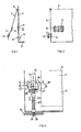
- the front panel of an electrical insert is designated by 1.
- 3 denotes the shelf.
- a circuit breaker, generally designated 5 is provided on the front plate 1 of the plug-in unit, with a bar 7 pivotably mounted in a knife-like manner about an axis 6, on which connecting contacts 9, usually for three network phases, are provided.
- a lever 15 is provided which can be operated manually from the outside.
- the axis 13 acts in a manner yet to be described on a locking arrangement, depending on the position of the lever 15.
- the lever 15 is shown in the locked position V.
- the unlocking of the locking arrangement takes place when the lever 15 is moved to the dash-dotted position E in FIG. 2.
- a schematically illustrated part 17 of the bar lies when the bar 7 is closed and consequently the voltage is switched on by closing of the contacts 9, 11 in the rotational path of the lever 15: the lever 15 cannot be rotated in the unlocking position corresponding to E when the switch bar 7 is closed. Accordingly, if the insert has already been removed, the latter cannot be inserted again with the switch bar 7 closed, because the lever 15 pivoted in the unlocking position in accordance with E prevents the switch bar 7 from being able to be closed. Thus, the procedure for removing the insert or.
- FIG. 3 shows a preferred embodiment variant of the technique generally shown in FIGS. 1 and 2.
- the lever 15 is pivotally mounted on the axis 13 on the front panel, the latter carrying a guide cam 19 on the inside of the front panel.
- the guide cam disc 19 is basically designed as a circular disc, but is formed along a chord 21.
- a locking armature 23 is mounted such that it can move linearly and at the end carries a contact plate 25, in engagement with the disk 19.
- the locking armature 23 is driven into the upper unlocking position by means of a spring 27, the armature end 29, depending on the position of the armature 23, in a locking opening 31, as driven in a support on the rack 33 respectively. pulled out. If the switching bar 7 is closed and thus rests on the front plate 1, the lever 15 cannot be pivoted into the unlocking position E shown in analogy to FIG. 2, in which the chord 21 of the disk 19 lies flush with the plate 25. In this circular disc position, the armature 23 assumes its uppermost position. In the locking position represented by V, the circular disc 19 rests with its circular arc on the plate 25 and the armature 23 is driven downwards in accordance with the difference in distance between the chord 21 and the axis 13 or the radius of the circular disc.
- the rotary movement of the lever 15 is very simply converted into a linear locking movement of the armature 23.
- the lever 15 can optionally be rotated further in the direction shown by P from the locking position V, because of the circular arc circumference of the disc 19, without effect on the locking anchor 23.
- the pivot lever 15 can be used to control other functions such as shown schematically, for example in positions P 1 and P 2 as an electrical switch.
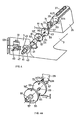
- a so-called automatic circuit breaker 35 is provided as an electrical switch for switching off the voltage, such as for a slide-in module that can be removed from a slide-in cabinet and which comprises a switching lever 37 for each phase, pivotable from an “off” position into an “on” position.
- the automat 35 allows, in addition to the manual switching on and off of the energy supply to the plug-in unit, the monitoring of operating conditions and switches automatically, for example when the current rises due to short-circuit reasons, to the "off” position.
- the automat 35 has an actuating bracket 39 known per se, with which the lever 37 can be actuated at the same time.
- An axis 41 is carried out on the front plate 1 of the insert, with an actuating button (not shown).
- a locking disk 43 with a groove 45 rides on the axis 41.
- a locking slide 47 is linearly guided and can be moved by means of a manually operated lever 49 against the restoring force of a schematically illustrated spring 51 from locking openings 69, such as on the side walls of the slide-in cabinet, provided the groove 45 is on the slide 47 is aligned.
- the axis 41 is mounted on a support 53 on the base 3 of the insert 1 and is fixed at its end, a first clutch disc 55 with a driving groove 57.
- On an axle stub 59 which, when assembled, protrudes into a corresponding coaxial bore 61 in the axis 41 and is supported there, rides a second clutch plate 63 with a driving pin 65 which protrudes into the groove 57 in the first clutch plate 55.
- the stub axle 59 also protruding on the opposite side of the clutch disc 63, runs freely in a corresponding bore 67 of a switch-side axle 69.
- a bracket 71 rides on the axle 69, into which a spring ball screw is screwed, axially parallel, with a sprung, the second Clutch disc 63 facing locking ball 73, aligned with a bore or recess 75 on the second clutch disc 63.
- the axis 69 is connected to the bracket 39, in the pivot axis of the lever 37 of the machine 35.
- a schematically illustrated spring 77 acts on the second clutch disc 63, with respect to the pivoting movement of the lever 37 in the off direction.
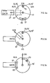
- FIGS. 5a to 5c are purely schematic and show the elements essential for the movement coupling between axis 41 and bracket 39 in different positions.
- the groove 45 and the slider are aligned with one another, the slider 47 can be moved in the direction shown by E against the force of the spring 51, which means that the Lock is released.
- the bolt 65 stands in the central region of the groove 57, the ball 73 is snapped into the recess 75. If, with the help of the rotary knob, the axis 41 is moved clockwise, as shown in FIG. 5b, into the "off” position, the locking slide 47 can no longer be pushed out of the openings 69, because it is on the part not provided with the groove 45 the locking disc 43. Due to the rotary movement of the axis 41, the groove 57 is also rotated on the first clutch disc 55 until the bolt 65 in the “off” position according to FIG.
- the spring 77 drives the second clutch disc 63 back and, via the latched ball 73 in the recess 75, also the lever 37 from the "on” to the "off” position.
- the automat 35 With the aid of the spring 77, the automat 35 can thus be set in the “on” or “off” position with the aid of the rotary knob on the axis 41, however, the slot can only be unlocked when it is returned to the unlocking position according to FIG. 5a.
- the automatic stop in the "off” position of the levers 37 holds the axis 69 and, via ball engagement, also the second clutch plate 63 with the bolt 65 in the position shown in FIG. 5a.
- the clutch disc 63 is rigidly connected to the axis 69.
- the spring 77 takes over the additional torque to be overcome by the automat 35 in the event of its operational relapse, so that it is ensured that the automat can respond with the required responsiveness, or the clutch disc 63 is provided with a continuous bore 75 'through which the ball 73 engages in a recess 75 "on the disk 55. Then the coupling torque takes over the latching connection, which is only released in the unlocking position according to FIG. 5a. In the latter case, the spring 77 supports the triggering moment from the automat 35.
- FIGS. 5a to 5c remain valid, with the omission or modification of the entered snap-in connection 73, 75 in 73, 75 ', 75 ".
- this safety arrangement is optimally connected to existing automatic machines.
Landscapes
- Engineering & Computer Science (AREA)
- Power Engineering (AREA)
- Switch Cases, Indication, And Locking (AREA)
- Driving Mechanisms And Operating Circuits Of Arc-Extinguishing High-Tension Switches (AREA)
- External Artificial Organs (AREA)
- Lock And Its Accessories (AREA)
- Cookers (AREA)
- Electrical Discharge Machining, Electrochemical Machining, And Combined Machining (AREA)
- Push-Button Switches (AREA)
Claims (16)
Priority Applications (1)
| Application Number | Priority Date | Filing Date | Title |
|---|---|---|---|
| AT85106261T ATE54778T1 (de) | 1984-07-10 | 1985-05-22 | Sicherheitsanordnung an einem elektrischen system. |
Applications Claiming Priority (2)
| Application Number | Priority Date | Filing Date | Title |
|---|---|---|---|
| CH3343/84A CH683882A5 (de) | 1984-07-10 | 1984-07-10 | Sicherheitsanordnung an einem elektrischen System. |
| CH3343/84 | 1984-07-10 |
Publications (2)
| Publication Number | Publication Date |
|---|---|
| EP0169331A1 EP0169331A1 (fr) | 1986-01-29 |
| EP0169331B1 true EP0169331B1 (fr) | 1990-07-18 |
Family
ID=4253914
Family Applications (1)
| Application Number | Title | Priority Date | Filing Date |
|---|---|---|---|
| EP85106261A Expired - Lifetime EP0169331B1 (fr) | 1984-07-10 | 1985-05-22 | Dispositif de sécurité pour système électrique |
Country Status (4)
| Country | Link |
|---|---|
| EP (1) | EP0169331B1 (fr) |
| AT (1) | ATE54778T1 (fr) |
| CH (1) | CH683882A5 (fr) |
| DE (1) | DE3578701D1 (fr) |
Families Citing this family (1)
| Publication number | Priority date | Publication date | Assignee | Title |
|---|---|---|---|---|
| DE202021102429U1 (de) | 2021-05-05 | 2022-08-08 | Feldbinder Spezialfahrzeugwerke Gmbh | Auslaufvorrichtung zum Entleeren eines Silobehälters, Silobehälter, Fahrzeug mit Silobehälter |
Family Cites Families (3)
| Publication number | Priority date | Publication date | Assignee | Title |
|---|---|---|---|---|
| FR2163379B1 (fr) * | 1971-12-16 | 1974-06-07 | Merlin Gerin | |
| DE3015259C2 (de) * | 1980-04-21 | 1982-04-15 | Siemens AG, 1000 Berlin und 8000 München | Schaltschrank |
| GB2111631B (en) * | 1981-12-19 | 1985-05-30 | Cutler Hammer Europa Limited | Electrical bay security device |
-
1984
- 1984-07-10 CH CH3343/84A patent/CH683882A5/de not_active IP Right Cessation
-
1985
- 1985-05-22 EP EP85106261A patent/EP0169331B1/fr not_active Expired - Lifetime
- 1985-05-22 DE DE8585106261T patent/DE3578701D1/de not_active Expired - Lifetime
- 1985-05-22 AT AT85106261T patent/ATE54778T1/de active
Also Published As
| Publication number | Publication date |
|---|---|
| ATE54778T1 (de) | 1990-08-15 |
| CH683882A5 (de) | 1994-05-31 |
| DE3578701D1 (de) | 1990-08-23 |
| EP0169331A1 (fr) | 1986-01-29 |
Similar Documents
| Publication | Publication Date | Title |
|---|---|---|
| DE69406026T2 (de) | Mechanische und elektrische Verriegelungsvorrichtung einer Fernbedienungseinheit für modulare Lastschalter | |
| DE3638305A1 (de) | Schliessmechanismus zur sicherung des kofferraumdeckels eines kraftfahrzeuges | |
| EP0621614A1 (fr) | Disjoncteur débrochable | |
| DE4409172C2 (de) | Sicherheitsvorrichtung zur gegenseitigen mechanischen Verriegelung von Schaltgeräten | |
| EP2135336B1 (fr) | Tiroir enfichable et armoire électrique pourvue d'une pluralité de tiroirs enfichables | |
| WO2013026518A1 (fr) | Dispositif d'entraînement pour un interrupteur à plusieurs positions | |
| DE10216594B4 (de) | Einschubkassette und Schaltschrank | |
| WO1994024743A1 (fr) | Installation de distribution electrique basse tension avec un support d'appareils et un dispositif de contact disjoncteur | |
| DE102009017559B3 (de) | Verriegelung | |
| EP1036400B1 (fr) | Unite appareil de commutation comprenant un appareil de commutation et un commutateur auxiliaire a avance de phase accouple | |
| EP1933345B1 (fr) | Système de verrouillage et de maneuvre d'un interrupteur pour générateur | |
| DE3701216A1 (de) | Universalantrieb | |
| DE10324209B4 (de) | Automatische Reaktivierungs- und Fernsteuerungsvorrichtung für zu steuernde modulare Schutzgeräte | |
| DE4312428C1 (de) | Handbetätigungsvorrichtung für gekapselte elektrische Schaltgeräte | |
| EP0169331B1 (fr) | Dispositif de sécurité pour système électrique | |
| EP1008712A1 (fr) | Gâche électrique | |
| EP0338328B1 (fr) | Armoire de commutation compartimentée | |
| EP0508041B1 (fr) | Commande de commutation pour appareils électriques à moyenne tension | |
| EP0500546B1 (fr) | Verrouillage pour un tiroir enfichable | |
| DE602004003949T2 (de) | Dreheingriffs-verriegelungsmechanismus für automatische sicherheitsabtrennung | |
| DE102007043137B3 (de) | Lasttrennschalter | |
| EP0710969A1 (fr) | Dispositif verrouillable entraîné manuellement pour appareils de commutation blindés | |
| DE3020593A1 (de) | Elektrischer schalter | |
| DE10061783C1 (de) | Verriegelungsvorrichtung | |
| EP1199395B1 (fr) | Verrouillage refermable pour verrou de porte |
Legal Events
| Date | Code | Title | Description |
|---|---|---|---|
| PUAI | Public reference made under article 153(3) epc to a published international application that has entered the european phase |
Free format text: ORIGINAL CODE: 0009012 |
|
| AK | Designated contracting states |
Designated state(s): AT BE CH DE FR GB IT LI LU NL SE |
|
| 17P | Request for examination filed |
Effective date: 19860719 |
|
| 17Q | First examination report despatched |
Effective date: 19880121 |
|
| GRAA | (expected) grant |
Free format text: ORIGINAL CODE: 0009210 |
|
| AK | Designated contracting states |
Kind code of ref document: B1 Designated state(s): AT BE CH DE FR GB IT LI LU NL SE |
|
| REF | Corresponds to: |
Ref document number: 54778 Country of ref document: AT Date of ref document: 19900815 Kind code of ref document: T |
|
| REF | Corresponds to: |
Ref document number: 3578701 Country of ref document: DE Date of ref document: 19900823 |
|
| ET | Fr: translation filed | ||
| ITF | It: translation for a ep patent filed | ||
| GBT | Gb: translation of ep patent filed (gb section 77(6)(a)/1977) | ||
| PLBE | No opposition filed within time limit |
Free format text: ORIGINAL CODE: 0009261 |
|
| STAA | Information on the status of an ep patent application or granted ep patent |
Free format text: STATUS: NO OPPOSITION FILED WITHIN TIME LIMIT |
|
| ITTA | It: last paid annual fee | ||
| 26N | No opposition filed | ||
| EPTA | Lu: last paid annual fee | ||
| EAL | Se: european patent in force in sweden |
Ref document number: 85106261.2 |
|
| PGFP | Annual fee paid to national office [announced via postgrant information from national office to epo] |
Ref country code: SE Payment date: 19960312 Year of fee payment: 12 |
|
| PGFP | Annual fee paid to national office [announced via postgrant information from national office to epo] |
Ref country code: LU Payment date: 19960401 Year of fee payment: 12 |
|
| PGFP | Annual fee paid to national office [announced via postgrant information from national office to epo] |
Ref country code: BE Payment date: 19960412 Year of fee payment: 12 |
|
| PGFP | Annual fee paid to national office [announced via postgrant information from national office to epo] |
Ref country code: GB Payment date: 19960507 Year of fee payment: 12 |
|
| PGFP | Annual fee paid to national office [announced via postgrant information from national office to epo] |
Ref country code: NL Payment date: 19960531 Year of fee payment: 12 Ref country code: AT Payment date: 19960531 Year of fee payment: 12 |
|
| PG25 | Lapsed in a contracting state [announced via postgrant information from national office to epo] |
Ref country code: LU Free format text: LAPSE BECAUSE OF NON-PAYMENT OF DUE FEES Effective date: 19970522 Ref country code: GB Effective date: 19970522 Ref country code: AT Effective date: 19970522 |
|
| PG25 | Lapsed in a contracting state [announced via postgrant information from national office to epo] |
Ref country code: SE Effective date: 19970523 |
|
| PG25 | Lapsed in a contracting state [announced via postgrant information from national office to epo] |
Ref country code: BE Effective date: 19970531 |
|
| BERE | Be: lapsed |
Owner name: KARL SCHWEIZER A.G. Effective date: 19970531 |
|
| PG25 | Lapsed in a contracting state [announced via postgrant information from national office to epo] |
Ref country code: NL Effective date: 19971201 |
|
| GBPC | Gb: european patent ceased through non-payment of renewal fee |
Effective date: 19970522 |
|
| EUG | Se: european patent has lapsed |
Ref document number: 85106261.2 |
|
| NLV4 | Nl: lapsed or anulled due to non-payment of the annual fee |
Effective date: 19971201 |
|
| PGFP | Annual fee paid to national office [announced via postgrant information from national office to epo] |
Ref country code: FR Payment date: 20040510 Year of fee payment: 20 |
|
| PGFP | Annual fee paid to national office [announced via postgrant information from national office to epo] |
Ref country code: DE Payment date: 20040603 Year of fee payment: 20 |
|
| PGFP | Annual fee paid to national office [announced via postgrant information from national office to epo] |
Ref country code: CH Payment date: 20040729 Year of fee payment: 20 |
|
| REG | Reference to a national code |
Ref country code: CH Ref legal event code: PL |