EP0166532B1 - Mécanisme de changement de vitesses à deux câbles pour transmissions - Google Patents
Mécanisme de changement de vitesses à deux câbles pour transmissions Download PDFInfo
- Publication number
- EP0166532B1 EP0166532B1 EP85303759A EP85303759A EP0166532B1 EP 0166532 B1 EP0166532 B1 EP 0166532B1 EP 85303759 A EP85303759 A EP 85303759A EP 85303759 A EP85303759 A EP 85303759A EP 0166532 B1 EP0166532 B1 EP 0166532B1
- Authority
- EP
- European Patent Office
- Prior art keywords
- axis
- movement
- motion
- crank
- pin
- Prior art date
- Legal status (The legal status is an assumption and is not a legal conclusion. Google has not performed a legal analysis and makes no representation as to the accuracy of the status listed.)
- Expired
Links
- 230000005540 biological transmission Effects 0.000 title claims abstract description 55
- 230000007246 mechanism Effects 0.000 title description 7
- 230000033001 locomotion Effects 0.000 claims abstract description 158
- 230000008878 coupling Effects 0.000 claims description 20
- 238000010168 coupling process Methods 0.000 claims description 20
- 238000005859 coupling reaction Methods 0.000 claims description 20
- 230000000694 effects Effects 0.000 description 7
- 238000006073 displacement reaction Methods 0.000 description 5
- 230000007935 neutral effect Effects 0.000 description 5
- 230000004044 response Effects 0.000 description 5
- 230000003993 interaction Effects 0.000 description 4
- 230000000712 assembly Effects 0.000 description 1
- 238000000429 assembly Methods 0.000 description 1
- 230000008859 change Effects 0.000 description 1
- 230000009977 dual effect Effects 0.000 description 1
- 210000005069 ears Anatomy 0.000 description 1
- 238000009434 installation Methods 0.000 description 1
- 230000009347 mechanical transmission Effects 0.000 description 1
- 230000003245 working effect Effects 0.000 description 1
Images


Classifications
-
- F—MECHANICAL ENGINEERING; LIGHTING; HEATING; WEAPONS; BLASTING
- F16—ENGINEERING ELEMENTS AND UNITS; GENERAL MEASURES FOR PRODUCING AND MAINTAINING EFFECTIVE FUNCTIONING OF MACHINES OR INSTALLATIONS; THERMAL INSULATION IN GENERAL
- F16H—GEARING
- F16H61/00—Control functions within control units of change-speed- or reversing-gearings for conveying rotary motion ; Control of exclusively fluid gearing, friction gearing, gearings with endless flexible members or other particular types of gearing
- F16H61/26—Generation or transmission of movements for final actuating mechanisms
- F16H61/36—Generation or transmission of movements for final actuating mechanisms with at least one movement being transmitted by a cable
-
- Y—GENERAL TAGGING OF NEW TECHNOLOGICAL DEVELOPMENTS; GENERAL TAGGING OF CROSS-SECTIONAL TECHNOLOGIES SPANNING OVER SEVERAL SECTIONS OF THE IPC; TECHNICAL SUBJECTS COVERED BY FORMER USPC CROSS-REFERENCE ART COLLECTIONS [XRACs] AND DIGESTS
- Y10—TECHNICAL SUBJECTS COVERED BY FORMER USPC
- Y10T—TECHNICAL SUBJECTS COVERED BY FORMER US CLASSIFICATION
- Y10T74/00—Machine element or mechanism
- Y10T74/20—Control lever and linkage systems
- Y10T74/20012—Multiple controlled elements
- Y10T74/20018—Transmission control
- Y10T74/20049—Transmission controlled by flexible cable
-
- Y—GENERAL TAGGING OF NEW TECHNOLOGICAL DEVELOPMENTS; GENERAL TAGGING OF CROSS-SECTIONAL TECHNOLOGIES SPANNING OVER SEVERAL SECTIONS OF THE IPC; TECHNICAL SUBJECTS COVERED BY FORMER USPC CROSS-REFERENCE ART COLLECTIONS [XRACs] AND DIGESTS
- Y10—TECHNICAL SUBJECTS COVERED BY FORMER USPC
- Y10T—TECHNICAL SUBJECTS COVERED BY FORMER US CLASSIFICATION
- Y10T74/00—Machine element or mechanism
- Y10T74/20—Control lever and linkage systems
- Y10T74/20012—Multiple controlled elements
- Y10T74/20018—Transmission control
- Y10T74/2014—Manually operated selector [e.g., remotely controlled device, lever, push button, rotary dial, etc.]
- Y10T74/20159—Control lever movable through plural planes
-
- Y—GENERAL TAGGING OF NEW TECHNOLOGICAL DEVELOPMENTS; GENERAL TAGGING OF CROSS-SECTIONAL TECHNOLOGIES SPANNING OVER SEVERAL SECTIONS OF THE IPC; TECHNICAL SUBJECTS COVERED BY FORMER USPC CROSS-REFERENCE ART COLLECTIONS [XRACs] AND DIGESTS
- Y10—TECHNICAL SUBJECTS COVERED BY FORMER USPC
- Y10T—TECHNICAL SUBJECTS COVERED BY FORMER US CLASSIFICATION
- Y10T74/00—Machine element or mechanism
- Y10T74/20—Control lever and linkage systems
- Y10T74/20012—Multiple controlled elements
- Y10T74/20201—Control moves in two planes
-
- Y—GENERAL TAGGING OF NEW TECHNOLOGICAL DEVELOPMENTS; GENERAL TAGGING OF CROSS-SECTIONAL TECHNOLOGIES SPANNING OVER SEVERAL SECTIONS OF THE IPC; TECHNICAL SUBJECTS COVERED BY FORMER USPC CROSS-REFERENCE ART COLLECTIONS [XRACs] AND DIGESTS
- Y10—TECHNICAL SUBJECTS COVERED BY FORMER USPC
- Y10T—TECHNICAL SUBJECTS COVERED BY FORMER US CLASSIFICATION
- Y10T74/00—Machine element or mechanism
- Y10T74/20—Control lever and linkage systems
- Y10T74/20396—Hand operated
- Y10T74/20402—Flexible transmitter [e.g., Bowden cable]
- Y10T74/2042—Flexible transmitter [e.g., Bowden cable] and hand operator
Definitions
- This invention relates to improvements in remotely controlled actuator mechanisms requiring two independent modes of motion and, more particularly, relates to an improved push-pull cable system for shifting gears in a vehicle transmission by operation of a gearshift lever remotely located from the transmission.
- a transmitter unit is located in close proximity to the vehicle operator and is under the operator's control through means of a transmitter unit control member, for example, the gearshift lever.
- the lever is guided for motion in a first mode, such as fore and aft, so as to move a crank arm through an angular range and produce longitudinal displacement of a first push-pull cable that will be designated as the shift cable through a coupling of such cable to a receiver unit, which is located adjacent the transmission to effect shifting of the transmission.
- the gearshift lever is also movable in a side-to-side motion by the operator pivoting the lever about the fore/aft axis of the cab.
- the side-to-side motion is transformed by a linkage mechanism to a longitudinal displacement of a second push-pull cable that will be designated as the select cable, which, again, is coupled to a linkage in the receiver unit to effectuate selection of the desired gear rail in the transmission.
- the linkage connecting the gearshift lever with the shift cable is so related to the linkage connecting the gearshift lever to the select cable that there is substantially no interaction between the longitudinal movement of the two push-pull cables as the gearshift lever is moved in each of the two modes of motion.
- While the transmitter described can be used with any receiver capable of accepting longitudinal movement of two independent cables to effect operation of the transmission, for example, the receiver unit described in our copending US Patent Application Serial No. 340,537, filed January 19, 1982, (corresponding to EP 0084239) a preferred embodiment of the receiver of the present system is useful for connection of the transmitter to a transmission of the type manufactured by Zahnradfabrik Friedrichshafen of Friedrichshafen, West Germany and provides a selection linkage connected to the select cable that transforms the longitudinal motion of the select cable into a longitudinal linear motion of an output rod connected to the transmission to select the desired gear rail.
- the shift cable from the transmitter is connected to a second linkage in the receiver that transforms the longitudinal motion of the shift cable to a rotational motion of the output rod to effectuate actual engagement of the desired gears in the selected gear rail.
- the motion of the first and second linkages in response to the motion of the shift and select cables is independent, one of the other.
- FIG 1 illustrates a preferred embodiment of a transmitter assembly T made in accordance with the principles of the present invention for allowing an operator located remotely from a mechanical transmission to shift the gears in the transmission.
- the transmitter assembly T is housed within a casing 10 and is typically mounted beneath the floor of a truck cab adjacent the operator and a shift lever 12, a portion of which is illustrated in Figure 1, extends upwardly through the floor of the cab to be grasped by the operator.
- the gearshift lever 12 is typically operable in two modes of motion. Movement in a first mode of motion effectuates selection of one of the gear rails in the remote transmission unit (not shown) and operation in the second mode causes selective engagement of one of the drive gears in the transmission unit associated with the gear rail that has been selected.
- the gear rail selection is accomplished by movement of the shift lever 12 side to side as shown by arrow 11, while engagement of the gear selected is accomplished by movement of the gearshift lever 12 in a fore/aft direction, as shown by arrow 13.
- movement of the gearshift lever 12 is transformed into associated longitudinal movement of first and second push-pull cables 14 and 16 that are connected to linkages in a receiver unit R, also shown in Figure 1, mounted adjacent the transmission unit T.
- the receiver accepts the longitudinal movement of the respective push-pull cables and transforms the motion into the proper motion required to accomplish gear selection and engagement in the transmission.
- the gearshift lever 12 fits within a bore of collar 18 and is shown in Figures 1, and 4 in essentially the neutral position.
- the lever 12 is pinned to the collar 18 so that the lever 12 cannot rotate within the collar.
- the collar 18 is integrally formed with a yoke 20 that includes first and second arms 20a and 20b, each of the arms having associated collars 22a and 22b formed at their ends.
- Coaxial bores are formed within the collars 22a and 22b, the axis of the bores being oriented transversely with respect to the cab.
- the yoke 20 is pivotally connected to a center arm 24 by a pin 26 that passes through the bores in each of the collars 22a and 22b and a bore formed coaxially in an ear 28 formed at the top of the center arm 24.
- the gearshift lever can then be moved in a fore/aft direction and will pivot about the transversely oriented pin 26.
- the center arm 24 includes a downwardly extending finger 24a and an upwardly opening yoke portion that culminates in two spaced collars 24b and 24c located on opposite sides of the ear 28.
- the collars 24b and 24c have coaxial bores formed therein, the axis of the bores lying parallel to the fore/aft axis of the cab.
- Pins 30 and 32 are inserted into the bores in the collars 24b and 24c and are mounted within holes formed in the casing 10 of the transmitter assembly.
- the center arm 24 is therefore mounted for swinging movement about the axis of the pins 30 and 32 as the gearshift lever 12 is moved in a transverse direction.
- the collar 22b has a fork member extending downwardly and integrally formed with the collar, the fork member having fingers 34a and 34b spaced from one another to form an elongated slot between the fingers. Trapped within the slot is a pin 36 that extends in a transverse direction from a shift crank arm 38 that is mounted for swinging movement about an axis parallel to the transverse axis of the cab on a pin 40 that passes through a collar 42 formed on the lower end of the finger 24a of center arm 24.
- the upper end of the shift crank arm has mounted thereon the ball element 44 of a ball-and-socket coupling.
- the complemental socket member 46 is carried by a slide rod 48 that is a part of a terminal assembly 49 attached to shift cable 16.
- Movement of the shift lever 12 in the fore/aft direction pivots the yoke 20 about the pin 26 and causes the fork fingers 34a and 34b to move the pin 36 in a fore/ aft direction, which, in turn, pivots the shift crank 38 about the pin 40.
- the ball-and-socket coupling 44, 46 is carried with the crank and causes a linear movement of the shift cable 16 in the fore/aft or longitudinal direction.
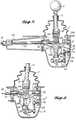
- FIGs 2 and 3 The interaction between the movement of the shift lever 12 and the shift capable 16 is more clearly shown in Figures 2 and 3.
- the shift lever is in essentially a neutral position.
- a boot 17 of rubber or other flexible material surrounds the lever 12 and seals the transmitter unit against entry of dirt and moisture without impeding motion of the gearshift lever 12 in either mode.
- the fork fingers 34a and 34b are upright as is shift crank 38.
- the shift lever 12 is shown canted to the right, which corresponds to a forward movement of the lever.
- the yoke 20 and the fork member pivot about pin 26 and the finger 34a pushes the pin 36 to the left.
- the force on pin 36 causes the shift crank 38 to pivot to the left about the pin 40 thereby moving the ball and socket coupling 44, 46 to the left.
- a fork is used to engage the pin on the shift crank, it would be possible simply to use a slot cut in a closed member; however, the fork permits a change in ratio of movement between the shift lever and the cable to accommodate changes in ratio of the transmission, which is being controlled by the transmitter assembly. As the ratio is changed, the relationship between the fork and the crank arm can be adjusted to slide the pin upwardly or downwardly within the slot formed between the fingers to accommodate such ratio changes. If a closed member were used, and the system designed for a single type of transmission with a fixed ratio it would still be necessary to make the opening for the pin slightly larger than the diameter of the pin to provide some small vertical clearance as there is some minor vertical movement of the pin 36 during operation of the shift crank 38 and gearshift lever 12.
- the shift cable 16 moves ⁇ 1 inch, i.e., a total of two inches of travel, in shifting the transmission.
- the desired handle stroke of the gearshift lever handle 15 is ⁇ 3 inches to ⁇ 5 inches; for a range of six to ten inches of total motion. Since the gearshift lever is approximately 24 inches long in order to place the end of the gearshift lever at a correct height for easy operation by a truck operator, the linkage created by the fork member and the shift crank is arranged to provide the correct travel of the respective members of the transmitter assembly.
- the selection of the gear rail in the transmission is effected by movement of the gearshift lever in a transverse or side-to-side direction.
- the select cable 14 moves in a longitudinal direction to transmit the control from the operator to the receiver unit located adjacent the transmission. It is therefore necessary that the transmitter linkage transform the transverse motion of the gearshift lever to a longitudinal motion of the shift cable 14.
- transverse movement of the shift lever 12 pivots the entire center arm assembly 24 about pins 30 and 32.
- Such motion of the center arm 24 carries with it the shift crank but does not cause any longitudinal motion of the shift cable 16.
- a select crank 50 is pivotally mounted on the pin 40 passing through the collar formed at the bottom of the finger 24a of center arm 24 and is capable of pivotal motion in a fore/ aft direction.
- a ball 52 that is one element of the ball-and-socket coupling, the socket member 54 being attached to a slide rod 56 that is part of the terminal assembly 57 attached to select cable 14. Pivotal motion of the select crank 50 in the fore/aft direction therefore effectuates longitudinal or fore/aft linear movement of the select cable 14.
- a ball member 58 is mounted at the end of a pin 60 and then the pin 60 is inserted into a bore in the lower end of the select crank 50 vertically aligned with the axis of rotation of the select crank. The ball 58 engages a socket 64 at a first end of a select link member 66.
- a second end of the select link member 66 has a socket member 68 affixed thereto that engages a ball 70 on the end of a pin 72 which is supported in member 10' and which, in turn is mounted to the case of the transmitter unit.
- the length of the link member 66 is chosen such that upon pivotal movement of the center arm 24 about the longitudinal axis the select link 66, since it is affixed at one end to the case, forces a fore/aft pivotal motion of the select link 50. In this manner, the transverse pivotal motion of the gearshift lever 12 is transformed into a fore/aft pivotal motion of the select link 50 and in turn a linear longitudinal movement in the fore/aft direction of the select cable 14.
- Figure 4 shows the shift lever 12 in the neutral or vertical position. In this state, the select crank 50 is also in the vertical position.
- the center arm 24 is pivoted to the right about the axis of pins 30 and 32.
- the lower end of link member 66 is carried with the center arm; however, the upper end of the link member 66 is affixed to the case and cannot translate.
- the link member 66 Since the link member 66 is inextensible, the otherwise binding effect of the motion of the lower end of the rod is transformed by the ball-and-socket couplings at the ends of the rod into a fore/aft displacement of the lower end of the link member 66, which causes a cooperative fore/aft tilt of the select crank 50.
- the select crank 50 pivots about pin 40 to the right, which corresponds to a forward motion since Figure 6 is a side view.
- the select crank 50 carries with it the ball-and-socket coupling 52, 54 and thereby the slide rod 56.
- the select 14 cable is also moved in a forward direction by the sideward tilt of the gearshift lever 12.
- the casing 10 of the transmitter will contain a series of holes at predetermined locations so that the fixation point of the pin 72 to the casing can be changed to accommodate transmissions of different ratios, a particular hole in the casing being associated with a transmission of given ratio.
- the typical movement of the select cable to cause proper selection of the transmission gears is ⁇ 1 inch or a total travel of two inches.
- the shift crank 50, select link 66, and center arm 24 are typically designed to provide a handle movement by the operator of a range of ⁇ 2 inches to ⁇ 3 inches for a total movement range of four to six inches to effectuate such two-inch range of travel of the select cable.
- select cable 14 has a terminal assembly 80 that includes an extendable rod 82 that terminates in a socket fitting 84 of a ball-and-socket coupling.
- the ball fitting 86 of that coupling is mounted to an ear 88 of a crank arm assembly 90 that is pivotable about a transverse axis and is mounted on a pin 92 affixed to the case 94 of the receiver assembly.
- the crank assembly 90 includes a planar portion 90a vertically oriented as shown in Figure 1, and parallel to the longitudinal axis of the receiver.
- the ear member 88 extends transversely from the planar member 90a and essentially orthogonal to it.
- a second ear 90b extends obliquely from the planar member 90a and is oriented and positioned such that pivotal motion of the ear 88 about the axis of pin 92 is translated into an arcuate motion of the ear 90b.
- the ear 90b has a ball element 96 mounted to it, which is a part of a ball-and-socket coupling.
- the socket portion 98 of the ball-and-socket coupling is at one end of a linear link member 100 and the other end of the link member 100 has a socket member 102 attached to it that engages a ball member 104 attached to an ear 106a integrally formed with a rotational coupling member 106 that surrounds a shaft 108 that extends out from the case of the receiver unit.
- the link member 100 is designed such that the arcuate motion of the ear 90b is transformed into a linear motion in a vertical direction, as pictured in Figure 1, of the ear 106a.
- the collar member 106 is tightly clamped on the rod 108 by a threaded bolt 109 so that motion of the ear 106a carries with it the rod 108.
- the rod 108 extending from the receiver case extends into the transmission associated with the receiver and is utilized to move a member in the transmission that selects the desired gear rail in the transmission. Engagement of the gears in the transmission is caused by a rotational movement of the same rod 108 and the rotation of the rod 108 is caused by the movement of the shift cable 14 in response to motion of the gearshift lever 12.
- the shift cable 16 enters the receiver unit and has a terminal assembly 110 attached to it.
- the terminal assembly 110 includes an extendable rod 112 that terminates in a socket fitting 114 of a ball-and-socket coupling.
- the ball member 116 of that ball-and-socket coupling is mounted to the end of an arm 118 that extends from the rotational collar 106 clamped to rod 108.
- Fore/aft movement of the cable 16 causes fore/aft movement of the extendable rod 112, which, in turn, causes a rotational movement about its own axis of the rod 108.
- the rotational movement of the rod 108 in response to the movement of the cable 16, which, in turn, is in response to the movement of the shift lever 12, causes engagement of the selected gears in the transmission to which the receiver unit is coupled.
- the critical feature of the receiver unit is that while the same rod 108 is utilized to actuate both selection and engagement of the gears in the transmission, it is necessary to keep the selection and shifting motions independent of one another.
- the length of the link 100 and the position and angle of the ears 90b and 106a are chosen such that the rotational movement of the collar 106 in response to the linear movement of the shift cable 16 does not in any way affect the linear position of the rod 108 as determined by the select cable 14 and link 100.
- linear up and down movement of the rod 108 induced by movement of select cable 14 will not have an effect on the movement of the shift cable 16 because of their orthogonal relationship.
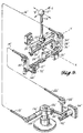
- the transmitter and receiver are shown in somewhat schematic form and are reduced to their basic moving parts.
- the transmitter consists of the gearshift lever 12' that moves in two basic modes, both fore/aft and in a transverse plane.
- the yoke assembly 20' and the center arm assembly 24' form essentially a universal joint that permits motion of the gearshift lever in the fore/aft plane about pivot pin 26' without causing any motion in the transverse direction.
- motion in a transverse direction causes the center arm to pivot about pins 30' and 32' without causing any fore/aft motion of either the gearshift lever or the yoke 20'.
- Figure 9 clearly shows the select link 66' tied at its upper end to the casing 10' of the transmitter and attached at the lower end to the select crank arm 50'.
- Each end of the select link 66' has a ball-and-socket assembly associated with it to provide the necessary freedom of motion to translate the transverse motion of gearshift lever 12' into longitudinal linear motion of the select cable 14'.
- the schematic representation of the receiver shown in Figure 9 more clearly shows the connecting link 100' having a ball and socket on each end thereof for translating the longitudinal linear motion of select cable 14' into a linear motion of the rod 108' in a vertical direction.
- the shift cable 16' is connected by a ball-and-socket joint directly to a lever arm 118' extending from the collar 106' clamped to the rod 108' so that the linear motion of the shift cable 16' is translated to rotational movement of the rod 108'.
- link 100' must be sized and the angle such that even though both the shift cable 16' and select cable 14' are connected to the rod 108', the rotational motion of the rod does not have an effect on the vertical/linear motion of the rod caused by movement of the select cable and, likewise, the movement of the select cable does not cause any rotational movement of the rod so that the two cable inputs remain independent of one another at all times.
- the essential function of the transmitter is to cause the motion of the gearshift lever by the operator to be translated into independent linear motions of two cables exiting the transmitter.
- the function of the receiver is to take an input that consists of linear motion of two independent push-pull cables, one of which indicates gear selection and one that indicates shifting, and couple those inputs to a transmission in a manner to actually cause a shift of gears in the transmission.
- any receiver that accepts the linear motion of two independent shift and select cables can be operated through use of the transmitter of the present invention and, likewise, the receiver of the present invention can accept an input in the form of linear motion of two independent shift and select cables from any transmitter that outputs those types of signals.
- the transmitter of the present invention could be used with a receiver, for example, of the type described in my copending United States patent application, Serial No. 340,537 (corresponding to EP-A-0084239) and, likewise, the receiver of the present invention could be used with a transmitter of the type described in my copending patent application Serial No.
Landscapes
- Engineering & Computer Science (AREA)
- General Engineering & Computer Science (AREA)
- Mechanical Engineering (AREA)
- Gear-Shifting Mechanisms (AREA)
- Arrangement Or Mounting Of Control Devices For Change-Speed Gearing (AREA)
- Mechanical Control Devices (AREA)
Claims (5)
Priority Applications (1)
| Application Number | Priority Date | Filing Date | Title |
|---|---|---|---|
| AT85303759T ATE46974T1 (de) | 1984-06-25 | 1985-05-29 | Getriebeschalteinrichtung mit zwei drahtzuegen. |
Applications Claiming Priority (2)
| Application Number | Priority Date | Filing Date | Title |
|---|---|---|---|
| US06/623,977 US4583417A (en) | 1984-06-25 | 1984-06-25 | Two-cable shifting mechanism for transmissions |
| US623977 | 1996-03-29 |
Publications (2)
| Publication Number | Publication Date |
|---|---|
| EP0166532A1 EP0166532A1 (fr) | 1986-01-02 |
| EP0166532B1 true EP0166532B1 (fr) | 1989-10-04 |
Family
ID=24500112
Family Applications (1)
| Application Number | Title | Priority Date | Filing Date |
|---|---|---|---|
| EP85303759A Expired EP0166532B1 (fr) | 1984-06-25 | 1985-05-29 | Mécanisme de changement de vitesses à deux câbles pour transmissions |
Country Status (5)
| Country | Link |
|---|---|
| US (1) | US4583417A (fr) |
| EP (1) | EP0166532B1 (fr) |
| AT (1) | ATE46974T1 (fr) |
| CA (1) | CA1242957A (fr) |
| DE (1) | DE3573481D1 (fr) |
Families Citing this family (30)
| Publication number | Priority date | Publication date | Assignee | Title |
|---|---|---|---|---|
| WO1986001161A1 (fr) * | 1984-08-04 | 1986-02-27 | Zahnradfabrik Friedrichshafen Ag | Organe de couplage |
| US4671131A (en) * | 1986-02-18 | 1987-06-09 | Cablecraft, Inc. | Transmitter for use with a two-cable shifting mechanism for a transmission |
| US4693135A (en) * | 1986-06-05 | 1987-09-15 | Wickes Manufacturing Company | Manually operable gearshift mechanism |
| JP2629871B2 (ja) * | 1988-08-29 | 1997-07-16 | スズキ株式会社 | 車両用変速機 |
| JP2524826B2 (ja) * | 1988-11-17 | 1996-08-14 | トヨタ自動車株式会社 | 手動変速機の変速操作装置 |
| US6955915B2 (en) * | 1989-06-07 | 2005-10-18 | Affymetrix, Inc. | Apparatus comprising polymers |
| JPH0333561A (ja) * | 1989-06-29 | 1991-02-13 | Suzuki Motor Corp | シフト機構 |
| US5179867A (en) * | 1989-12-28 | 1993-01-19 | Aisin Aw Co., Ltd. | Automatic transmission for vehicle |
| JPH0415363A (ja) * | 1990-05-02 | 1992-01-20 | Nippon Cable Syst Inc | 変速機操作装置 |
| US5321993A (en) * | 1991-03-08 | 1994-06-21 | Chrysler Corporation | Transmission shift control apparatus |
| JPH0655951A (ja) * | 1992-08-05 | 1994-03-01 | Nippon Cable Syst Inc | 変速機操作装置 |
| US5287743A (en) * | 1992-09-24 | 1994-02-22 | Dura Mechanical Components, Inc. | Manual transmission shifter |
| ES2104486B1 (es) * | 1992-10-21 | 2006-10-01 | Nippon Cable System Inc | Dispositivo de operacion de transmision. |
| BR7401842U (pt) * | 1994-10-19 | 1995-03-21 | Paolo Paparoni | Disposição introduzida em mecanismo de articulação para alavanca de câmbio automotivo com acionamento por cabos. |
| IT1280789B1 (it) * | 1995-01-18 | 1998-02-11 | Sila Telecomandi Srl | Gruppo di comando di un cambio di velocita' per un autoveicolo. |
| SE506227C2 (sv) * | 1996-03-05 | 1997-11-24 | Scandmec Ab | Manöveranordning |
| SE508010C2 (sv) * | 1996-11-27 | 1998-08-10 | Scandmec Ab | Växelreglage till en växellåda |
| US5845536A (en) * | 1997-03-21 | 1998-12-08 | Saturn Corporation | Transmission shift control mechanism |
| JP3167958B2 (ja) * | 1997-05-08 | 2001-05-21 | コナミ株式会社 | 多方向切替操作装置 |
| DE10127765A1 (de) * | 2000-06-23 | 2002-01-03 | Luk Lamellen & Kupplungsbau | Verfahren und Steuerungseinrichtung zur Steuerung von Betriebskennwerten eines Antriebsstranges |
| US6539822B1 (en) * | 2000-08-09 | 2003-04-01 | Trw Inc. | Transmission shifter assembly with indicator |
| JP3611111B2 (ja) * | 2001-04-17 | 2005-01-19 | 川崎重工業株式会社 | 車両用変速レバー装置 |
| FR2919845B1 (fr) * | 2007-08-09 | 2010-02-19 | Europ De Fabrications Ind Sefi | Systeme de commande par cable d'une boite de vitesses pour poids lourd a cabine basculante |
| IT1391422B1 (it) * | 2008-08-01 | 2011-12-23 | Ultraflex Spa | Comando monoleva per il controllo combinato della alimentazione di motori marini e dell'invertitore |
| FR2946112B1 (fr) * | 2009-05-28 | 2012-12-21 | Dura Automotive Systems Sas | Dispositif de commande par cables d'une boite de vitesses mecanique pour vehicule automobile au moyen d'un levier |
| JP5809504B2 (ja) * | 2011-09-22 | 2015-11-11 | 富士機工株式会社 | シフトレバー装置 |
| CN105020382B (zh) * | 2014-04-29 | 2017-02-22 | 中国科学院沈阳自动化研究所 | 一种基于手动挡汽车的自动换挡机构 |
| KR101905950B1 (ko) * | 2016-04-08 | 2018-10-08 | 현대자동차주식회사 | 수동변속기의 변속레버 어셈블리 |
| IT201600121952A1 (it) * | 2016-12-01 | 2018-06-01 | Silatech S R L | Cambio di velocità per autoveicolo con sistema di comando manuale o servoassistito. |
| TR201809305A2 (tr) * | 2017-06-30 | 2019-01-21 | Cnh Industrial India Private Ltd | Zi̇rai̇ bi̇çerdöver şanziman si̇stemleri̇ ve usulleri̇ |
Family Cites Families (15)
| Publication number | Priority date | Publication date | Assignee | Title |
|---|---|---|---|---|
| US2250820A (en) * | 1938-12-17 | 1941-07-29 | Fuller Mfg Co | Remote control for transmissions |
| US2280047A (en) * | 1939-01-07 | 1942-04-14 | Automatic Shifters Inc | Gear shifting mechanism |
| US2280157A (en) * | 1940-07-13 | 1942-04-21 | Divco Twin Truck Company | Stand drive vehicle |
| US2497930A (en) * | 1948-04-02 | 1950-02-21 | Ross Gear & Tool Co | Transmission control |
| US2547317A (en) * | 1948-12-17 | 1951-04-03 | Caterpillar Tractor Co | Transmission shifting device |
| US3517568A (en) * | 1968-07-05 | 1970-06-30 | North American Rockwell | Single lever control |
| US3541877A (en) * | 1969-01-23 | 1970-11-24 | Richard D Houk | Single lever control for coordinating multiple motion transmitting devices |
| US3604284A (en) * | 1970-05-25 | 1971-09-14 | North American Rockwell | Control device for applying balanced forces to a pair of servient mechanisms |
| US4152950A (en) * | 1977-05-10 | 1979-05-08 | Incom International Inc. | Differential and push-pull control system |
| US4143560A (en) * | 1977-10-19 | 1979-03-13 | General Motors Corporation | Transmission shift control |
| US4328712A (en) * | 1980-01-24 | 1982-05-11 | Jsj Corporation | Lockout for gimbal-type automotive transmission gear shifter |
| US4270403A (en) * | 1979-02-26 | 1981-06-02 | Cablecraft, Inc. | Push-pull cable motor truck remote gear shift system and two-dimensional motion conversion and transmission apparatus therein |
| US4458549A (en) * | 1981-08-12 | 1984-07-10 | Toyota Jidosha Kogyo Kabushiki Kaisha | Select return mechanism for a transmission |
| US4483211A (en) * | 1982-01-19 | 1984-11-20 | Cablecraft, Inc. | Dual cable transmission gearshift mechanism |
| JPS5936829A (ja) * | 1982-08-26 | 1984-02-29 | Chuo Spring Co Ltd | 自動車用変速機操作装置 |
-
1984
- 1984-06-25 US US06/623,977 patent/US4583417A/en not_active Expired - Lifetime
-
1985
- 1985-05-29 AT AT85303759T patent/ATE46974T1/de active
- 1985-05-29 DE DE8585303759T patent/DE3573481D1/de not_active Expired
- 1985-05-29 EP EP85303759A patent/EP0166532B1/fr not_active Expired
- 1985-06-07 CA CA000483409A patent/CA1242957A/fr not_active Expired
Also Published As
| Publication number | Publication date |
|---|---|
| DE3573481D1 (en) | 1989-11-09 |
| EP0166532A1 (fr) | 1986-01-02 |
| ATE46974T1 (de) | 1989-10-15 |
| US4583417A (en) | 1986-04-22 |
| CA1242957A (fr) | 1988-10-11 |
Similar Documents
| Publication | Publication Date | Title |
|---|---|---|
| EP0166532B1 (fr) | Mécanisme de changement de vitesses à deux câbles pour transmissions | |
| EP0084239B1 (fr) | Appareil de commande à distance à double tringlerie | |
| US4671131A (en) | Transmitter for use with a two-cable shifting mechanism for a transmission | |
| EP0333429B1 (fr) | Dispositif de commande à distance | |
| CN1267663C (zh) | 电子选择汽车变速箱挡位的换挡装置 | |
| US4934208A (en) | Vehicle transmission shifter | |
| US4509384A (en) | Manual gearbox ratio change control device | |
| US5129278A (en) | Transmission operating device | |
| CA1151056A (fr) | Mecanisme de changement de vitesse | |
| JPS63815B2 (fr) | ||
| US4799397A (en) | Control device for a motor vehicle gearbox | |
| CA1081090A (fr) | Commande de transmission hydrostatique | |
| US5870929A (en) | Gear-shift device for an automatic gearbox | |
| US4276953A (en) | Shift linkage for a tilt cab truck | |
| KR20010015886A (ko) | 조정 장치 | |
| US4524634A (en) | Transmission shifting mechanism | |
| EP0448526A1 (fr) | Dispositif de commande de la boîte de vitesses d'un véhicule automobile | |
| US6951151B2 (en) | Manual transmission shifting device | |
| CA1237638A (fr) | Telecommande maitresse de passage des vitesses | |
| JPS622672Y2 (fr) | ||
| EP2596267B1 (fr) | Mécanisme de fonctionnement pour un câble bowden | |
| CN113700852A (zh) | 换挡器、换挡变速系统以及自动挡汽车 | |
| EP1555464A1 (fr) | Dispositif de commande externe pour la transmission d'un véhicule utilitaire. | |
| JPS61110221A (ja) | トランスミツシヨン操作装置 | |
| GB2129074A (en) | A steering column mounted gear change mechanism |
Legal Events
| Date | Code | Title | Description |
|---|---|---|---|
| PUAI | Public reference made under article 153(3) epc to a published international application that has entered the european phase |
Free format text: ORIGINAL CODE: 0009012 |
|
| AK | Designated contracting states |
Designated state(s): AT BE CH DE FR GB IT LI LU NL SE |
|
| 17P | Request for examination filed |
Effective date: 19860627 |
|
| 17Q | First examination report despatched |
Effective date: 19861208 |
|
| GRAA | (expected) grant |
Free format text: ORIGINAL CODE: 0009210 |
|
| AK | Designated contracting states |
Kind code of ref document: B1 Designated state(s): AT BE CH DE FR GB IT LI LU NL SE |
|
| PG25 | Lapsed in a contracting state [announced via postgrant information from national office to epo] |
Ref country code: LI Effective date: 19891004 Ref country code: CH Effective date: 19891004 |
|
| REF | Corresponds to: |
Ref document number: 46974 Country of ref document: AT Date of ref document: 19891015 Kind code of ref document: T |
|
| ET | Fr: translation filed | ||
| ITF | It: translation for a ep patent filed |
Owner name: JACOBACCI & PERANI S.P.A. |
|
| REF | Corresponds to: |
Ref document number: 3573481 Country of ref document: DE Date of ref document: 19891109 |
|
| REG | Reference to a national code |
Ref country code: CH Ref legal event code: PL |
|
| PG25 | Lapsed in a contracting state [announced via postgrant information from national office to epo] |
Ref country code: LU Free format text: LAPSE BECAUSE OF NON-PAYMENT OF DUE FEES Effective date: 19900531 |
|
| PLBE | No opposition filed within time limit |
Free format text: ORIGINAL CODE: 0009261 |
|
| STAA | Information on the status of an ep patent application or granted ep patent |
Free format text: STATUS: NO OPPOSITION FILED WITHIN TIME LIMIT |
|
| 26N | No opposition filed | ||
| PGFP | Annual fee paid to national office [announced via postgrant information from national office to epo] |
Ref country code: BE Payment date: 19930426 Year of fee payment: 9 |
|
| PGFP | Annual fee paid to national office [announced via postgrant information from national office to epo] |
Ref country code: AT Payment date: 19930504 Year of fee payment: 9 |
|
| ITTA | It: last paid annual fee | ||
| PG25 | Lapsed in a contracting state [announced via postgrant information from national office to epo] |
Ref country code: AT Effective date: 19940529 |
|
| PG25 | Lapsed in a contracting state [announced via postgrant information from national office to epo] |
Ref country code: BE Effective date: 19940531 |
|
| BERE | Be: lapsed |
Owner name: CABLECRAFT INC. Effective date: 19940531 |
|
| EAL | Se: european patent in force in sweden |
Ref document number: 85303759.6 |
|
| PGFP | Annual fee paid to national office [announced via postgrant information from national office to epo] |
Ref country code: GB Payment date: 20000420 Year of fee payment: 16 |
|
| PGFP | Annual fee paid to national office [announced via postgrant information from national office to epo] |
Ref country code: SE Payment date: 20000508 Year of fee payment: 16 |
|
| PGFP | Annual fee paid to national office [announced via postgrant information from national office to epo] |
Ref country code: NL Payment date: 20000530 Year of fee payment: 16 Ref country code: FR Payment date: 20000530 Year of fee payment: 16 |
|
| PGFP | Annual fee paid to national office [announced via postgrant information from national office to epo] |
Ref country code: DE Payment date: 20010423 Year of fee payment: 17 |
|
| PG25 | Lapsed in a contracting state [announced via postgrant information from national office to epo] |
Ref country code: GB Free format text: LAPSE BECAUSE OF NON-PAYMENT OF DUE FEES Effective date: 20010529 |
|
| PG25 | Lapsed in a contracting state [announced via postgrant information from national office to epo] |
Ref country code: SE Free format text: LAPSE BECAUSE OF NON-PAYMENT OF DUE FEES Effective date: 20010530 |
|
| PG25 | Lapsed in a contracting state [announced via postgrant information from national office to epo] |
Ref country code: NL Free format text: LAPSE BECAUSE OF NON-PAYMENT OF DUE FEES Effective date: 20011201 |
|
| GBPC | Gb: european patent ceased through non-payment of renewal fee |
Effective date: 20010529 |
|
| PG25 | Lapsed in a contracting state [announced via postgrant information from national office to epo] |
Ref country code: FR Free format text: LAPSE BECAUSE OF NON-PAYMENT OF DUE FEES Effective date: 20020131 |
|
| NLV4 | Nl: lapsed or anulled due to non-payment of the annual fee |
Effective date: 20011201 |
|
| PG25 | Lapsed in a contracting state [announced via postgrant information from national office to epo] |
Ref country code: DE Free format text: LAPSE BECAUSE OF NON-PAYMENT OF DUE FEES Effective date: 20021203 |