EP0165321A1 - Commutateur d'alimentation - Google Patents
Commutateur d'alimentation Download PDFInfo
- Publication number
- EP0165321A1 EP0165321A1 EP85900176A EP85900176A EP0165321A1 EP 0165321 A1 EP0165321 A1 EP 0165321A1 EP 85900176 A EP85900176 A EP 85900176A EP 85900176 A EP85900176 A EP 85900176A EP 0165321 A1 EP0165321 A1 EP 0165321A1
- Authority
- EP
- European Patent Office
- Prior art keywords
- fixed contact
- plate
- contact member
- arc
- movable contact
- Prior art date
- Legal status (The legal status is an assumption and is not a legal conclusion. Google has not performed a legal analysis and makes no representation as to the accuracy of the status listed.)
- Granted
Links
Images


Classifications
-
- H—ELECTRICITY
- H01—ELECTRIC ELEMENTS
- H01H—ELECTRIC SWITCHES; RELAYS; SELECTORS; EMERGENCY PROTECTIVE DEVICES
- H01H9/00—Details of switching devices, not covered by groups H01H1/00 - H01H7/00
- H01H9/30—Means for extinguishing or preventing arc between current-carrying parts
- H01H9/46—Means for extinguishing or preventing arc between current-carrying parts using arcing horns
Definitions
- the present invention relates to a power switch for switching on and off a current, and more particularly to an improvement in the circuit breaking performance of an electromagnetic contactor or a no-fuse circuit breaker, for example.
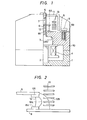
- FIG. 1 One conventional electromagnetic contactor is illustrated in Fig. 1.
- Designated at 1 is an attachment base molded of plastics, 2 a fixed laminated iron core r composed of silicon steel plates, 3 a movable laminated iron core composed of silicon steel plates, 4 a control coil for imposing a driving force to attract the movable iron core 3 and the fixed iron core 2 against the force of a tripping spring (not shown), 5 a cross bar molded of plastics and having a rectangular window, the cross bar 5 supporting the movable iron core 3 on a lower end thereof, 6 a movable contact member inserted through the rectangular window of the cross bar 5, 6A a movable contact on one end of the movable contact member 6, 7 a presser spring for pressing the movable contact member 6, 8 a fixed contact member disposed in confronting relation to the movable contact member 6 and supporting on one end a fixed contact 8A, the movable contact 6A being movable into and out of contact with the fixed contact 8A, and 88 a terminal
- Denoted at 9 is a terminal screw for connecting the body of the electromagnetic contactor to an external circuit, 10 a base to which the fixed contact 8 is attached, 11 an arc cover disposed in covering relation to the electromagnetic contactor, 12 an arc generated between the fixed contact 8A and the movable contact 6A, and 13 a plurality of parallel metal extinguishing plates of a magnetic material which lie parallel to the surface of the fixed contact member 8 to which the fixed contact 8A is joined.
- the arrangement of Fig. 1 is symmetrical, and only a righthand portion thereof is shown in cross section.
- the movable iron core 3 is separated from the fixed iron core 2 by a tripping mechanism (not shown), and the cross bar 5 is positioned as shown in Fig. 1.
- the fixed contact 8A and the movable contact 6A are separated from each other while an electric current is flowing therethrough to produce the arc 12 between the contacts 8A, 6A as shown in Figs. 1 and 3.
- the arc 12 is attracted to the magnetic metal extinguishing plates 13, and moved successively through positions 12A, 12B as shown in Fig. 2.
- the arc 12 is finally extinguished between the metal extinguishing plates 13 to thereby cut off the current.
- the conventional power switch (electromagnetic contactor) operates in the foregoing manner.
- the arc is extinguished, only those of the parallel metal extinguishing plates 13 which are positioned between the movable contact member 6 and the fixed contact member 8 are involved, but not all of the metal extinguishing plates 13 are utilized. Therefore, the circuit breaking performance is poor, and the contacts tend to wear at a high rate. Disclosure of the Invention:
- the leg of the arc 12 on the movable contact 6A is therefore easily transferred onto the commutation electrode 15, and the arc 12 is moved to a position 12A shown in Fig. 6.
- a current flows through the arc runner in the direction of the arrows A to drive the arc toward the metal extinguishing plates 13.
- the arc 12A is moved due to the magnetic field produced by the current flowing through the arc runner 14 and also due to the current flowing through the communication electrode 15.
- the arc 12 A is therefore transferred through positions 12B, 12C to a position 12D.
- the arc 12D is extinguished between the first plate 15A and the arc runner 14, whereupon the current is shut off.
- arc runner 14 is employed in the above embodiment, it may be dispensed with for improved circuit breaking performance and reduced wear on the movable contact.
- the present invention can be applied to a power switch having a fixed contact member 8 having a cross-sectional shape as shown in Fig. 7.
- the leg of the arc 12 is transferred from the fixed contact 8A to the fixed contact 8 under the magnetic field generated by a current (indicated by the arrow) flowing through the fixed contact member 8.
- a current indicated by the arrow
- the invention can be appleid to a power switch such as a no-fuse circuit breaker as illustrated in Fig. 8 for the same advantages.
- Designated at 17 is a shaft about which the movable contact member is rotatable, and 18 a stranded wire by which the commutation electrode 15 and the movable contact member 6 are electrically connected to each other.
- the reference numeral 14 indicatess an arc runner identical to that of Fig. 3.
- a high-tension power switch When a high-tension power switch is to be manufactured, it is necessary to increase the number of metal extinguishing plates 13. Since the excellent circuit breaking performance can be obtained by arranging the metal extinguishing plates 13 parallel to the surface of the fixed contact 8A, a high-tension power switch can be achieved without having to increase the area of installation of the power switch.
- Fig. 9 shows still another embodiment of the present invention. According to this embodiment, there is provided a power switch capable of quickly driving an arc generated between movable and fixed contacts by forming a slit extending from a recess in a commutation electrode to a first plate thereof, the slit having a width smaller than that of the recess.
- Fig. 9 is a perspective view of a commutation electrode according to this embodiment.
- Designated at 15F is a slit extending from a recess 15E to a first plate 15A and having a width smaller than that of the recess 15E.
- the electromagnetic contactor according to this embodiment is identical to that shown in Fig. 3, except for the commutation electrode 15.
- Fig. 10 is a perspective view of a commutation electrode according to a still further embodiment of the present invention.
- a slit 15F extends not only in the third plate 15C but also in a portion of the first plate 15A. Therefore, the difference between the path TBP and the path TCP is larger than that in Fig. 9.
- the arc 12A can be driven at a higher speed than the speed with the embodiment of Fig. 9, and the circuit breaking performance is further improved.
- the slit 15F should be narrower than the recess 15E.
- the present invention is applied to an electromagnetic contactor.
- the invention may be applied to a no-fuse circuit breaker.
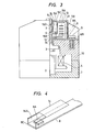
- Fig. 11 illustrates an arc extinguishing process in such a no-fuse circuit breaker to which the invention is applied.
- Denoted at 17 is a'shaft about which a movable contact member 6 is rotatable, and 18 a flexible stranded wire connecting a commutation electrode 15 to the movable contact member 6.
- the movable contact member 6 is rotatable about the shaft 17 for opening and closing the contacts 6A, 8A.
- the no-fuse circuit breaker is associated with an overcurrent detector and a control mechanism.
- the slit 15F is defined in the third plate 15C of the commutation plate 15, so that the arc 12 can be driven quickly for increased circuit breaking performance for hte same reasons as those in the embodiment of Fig. 9.
- the slit 15F may extend partly into the first plate 15A, instead of being defined only in the third plate 15C, for attaining the same advantages.
- the recess 15E extends from the fourth plate 15D tghrough the second plate 15B to the third plate 15C.
- the recess 15E may be defined only in the fourth plate 15D and the second plate 15B for the same advantages as those in the foregoing embodiments.
- the slit extending from the recess in the commutation electrode toward the first plate and narrower than the recess, as shown in Figs. 9 through 11, is effective in quickly driving an arc produced between the contacts, with the result that the circuit breaking performance can be increased.
- the third through first plates of the commutation electrode 15 are divided into lateral parts by a slit extending from the third plate to the first plate for quickly driving an arc for improved circuit breaking performance.
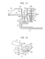
- Fig. 12 The embodiment of Fig. 12 is the same as the electromagnetic contactor shown in Fig. 3 except for the commutation electrode 15. Therefore, Fig. 12 fragmentarily shows a central portion including the commutation electrode 15.
- the commutation electrode 15 has a slit 15F extending from the third plate 15C to the first plate to divide the third plate 15C through the first plate 15A into lateral parts.
- Operation of the embodiment fragmentarily shown in Fig. 12 is the same as that of the electromagnetic contactor shown in Fig. 3, except for the following operation: When one leg of an arc 12A is produced at the point P in Fig.
- the arc is not influenced by a current IB flowing through a path TBP, but is largely affected by a current IC flowing through a path TCP since the commutation plate 15 is divided by the slit 15F up to the third plate 15A. Therefore, the arc 12A is forcibly driven upwardly under an increased upward driving force against being stuck at the point P.
- the arcing time is shortened and the arc energy is reduced. Since the arc energy is reduced, the circuit breaking performancecan be increased.
- the present invention can be applied to a no-fuse circuit breaker.
- a no-fuse circuit breaker to which the invention is applied is fragmentarily shown in Fig. 13.
- a movable contact member 6' is rotatable about a shaft 17 for opening and closing the contacts.
- a commutation electrode 15 is connected to the movable contact member 6 through a flexible stranded wire 18.
- the no-fuse circuit breaker is associated with an overcurrent detector and a control mechanism. When an overcurrent flows, it is detected by the overcurrent detector which causes the control mechanism to separate the movable contact 6A from the fixed contact 8A, producing an arc 12A which is extinguished in a process which is the same as that employed in the embodiment of Fig.
- the third plate 15C through the first plate 15A of the commutation electrode 15 are divided into lateral parts by a slit 15F extending from the third plate 15C to the first plate 15A, so that the circuit breaking performance can be improved for the same reasons as those in the embodiment of Fig. 12.
- the circuit breaking performance can be improved.
- Embodiments shown in Figs. 14 through 16 are designed to prevent the contacting area between the movable and fixed contact members from being abnormally heated.
- the fixed contact member 8 is of a C-shaped cross section as shown in Fig. 7 for increasing magnetic driving forces for driving the arc 12
- the heat produced in the contact area bewteen the movable contact 6A and the fixed contact 8A when a load current is continuously passed cannot easily be radiated toward the terminal 8B (Fig. 1), and hence the current passing capability of the electromagnetic contactor is lowered.
- the fixed contact member 8 and the movable contact member 6 is subject to an abnormal temperature rise, causing the cross bar 5 molded as of plastics to damage the base 10.
- Figs. 14 through 16 show modifications of the fixed contact and the arc runner.
- the fixed contact member has a contacting portion and a fixed portion integrally formed with the contact joint area and extending in the direction in which an arc runs.
- the length of the contacting portion in the direction in which the contacts are brought into and out of contact with each other is larger than the length of the fixed portion in the same direction.
- the arc runner has a recess through which the movable contact can pass and a free end, and also has an arc running portion positioned closer to the movable contact than the surface on which the fixed contact is joined to the fixed contact member.
- Figs. a4(a) and 14(b) are plan and side elevational views of a modified fixed contact member 8 according to the present invention.
- the fixed contact member 8 includes a contacting portion 8C ad a fixed portion 3D integrally-formed-with the contacting portion 8C and extending in the direction in which the arc runs.
- the length fl of the contacting portion 8C in the direction in which the contacts are brought into and out of contact with each other is larger than the length J2 of the fixed portion 8D in the same direction.
- the contacting portion 8C is in the form of a rectangular parallelepiped.
- Figs. 15(a) and 15(b) illustrate a modified combination of an arc runner 14 and a fixed contact member 8.
- Fig. 15(a) is a plan view
- Fig. 15(b) is a cross-sectional view taken along line X - X of Fig. 15(a).
- Designated at 14A is a recess through which the movable contact can pass when it is brought into and out of contact with the fixed contact 8A, 14B a free end, and 14C an arc running portion positioned closer to the movable contact (disposed above in Fig. 15(b)) than the surface on which the fixed contact 8A is joined to the fixed contact member 8.
- An arc runner 14 having these portions 14A, 14B, 14C is joined as by a screw or brazing to the fixed contact member 8 such that the direction of a current flowing in the arc runnng portion 14C after the leg of an arc on the fixed contact 8A has been transferred to the arc running portion 14C will be aligned with the direction of a current flowing through the movable contact member.
- the fixed contact member 8 and the arc runner 14 according to the above modification are incorporated in the electromagnetic contactor as-shown-in Fig. 3, and used as fragmentarily shown in Fig. 16 at an enlarged scale.
- the contacting portion 8C in the form of a rectangular parallelepiped can store a certain amount of heat for thereby preventing the cross bar 5 and the base 10 from being damaged by an abnormal temperature rise of the contact members 6, 8.
- the movable iron core 3 When the coil 4 is de-energiied, the movable iron core 3 is separated from the fixed iron core 2 by the non- illustrated tripping spring.
- The-movable contact 6A is therefore brought out of contact with the fixed conatct 8A, whereupon an arc 12 is generated between the contacts 6A, 8A as shown in Fig. 16.
- the arc 12 is attracted to the metal extinguishing plates 13 and transferred to a position 12A between the commutation electrode 15 and the arc runner 14.
- the arc 12A is then-attracted by the metal extinguishing plates 13 and driven by the magnetic field generated by currents flowing through the commutation electrode 15 and the arc runner 14.
- the arc 12A is therefore moved through a position 12B to a position 12C while being driven by the first plate 14A and the free end 14B of the arc runner 14, and then extinguished by the metal extinguishing plates 13.
- an arced gas produced while the arc is being generated is cooled as it passes through the pores in the porous metal plate 16, and then discharged out of the holes 11A in the arc cover 11. Since the arc runner 14 is provided as shown in Figs. 14 and 15, the circuit breaking performance can be improved even without using a fixed contact member 8 of a C-shaped in cross section.
- the contacting portion 8C is in the form of a rectangular parallelepiped for preventing the contacts 6A, 8A and the contact members 6, 8 from being heated to high temperature due to the heat generated where the contacts 6A, 6B contact each other when a load current flows therethrough.
- the current passing capability can be increased.
- the circuit breaking performance is not lowered.
- the contacting portion 8C is in the form of a rectangular parallelepiped, it may be cube-shaped for attaining the same advantages.
- the present invention is applied to an electromagnetic contactor, the invention is also applicable to other power switches such as a no-fuse circuit breaker as shown in Figs. 8, 11, and 13.
Abstract
Applications Claiming Priority (8)
| Application Number | Priority Date | Filing Date | Title |
|---|---|---|---|
| JP23114083A JPS60124321A (ja) | 1983-12-07 | 1983-12-07 | 電力開閉器 |
| JP231136/83 | 1983-12-07 | ||
| JP231140/83 | 1983-12-07 | ||
| JP23113683A JPS60124320A (ja) | 1983-12-07 | 1983-12-07 | 電力開閉器 |
| JP5310384A JPS60198014A (ja) | 1984-03-19 | 1984-03-19 | 電力開閉器 |
| JP53103/84 | 1984-03-19 | ||
| JP5310684A JPS60198017A (ja) | 1984-03-19 | 1984-03-19 | 電力開閉器 |
| JP53106/84 | 1984-03-19 |
Publications (3)
| Publication Number | Publication Date |
|---|---|
| EP0165321A1 true EP0165321A1 (fr) | 1985-12-27 |
| EP0165321A4 EP0165321A4 (fr) | 1988-10-06 |
| EP0165321B1 EP0165321B1 (fr) | 1992-01-08 |
Family
ID=27462866
Family Applications (1)
| Application Number | Title | Priority Date | Filing Date |
|---|---|---|---|
| EP85900176A Expired - Lifetime EP0165321B1 (fr) | 1983-12-07 | 1984-12-07 | Commutateur d'alimentation |
Country Status (4)
| Country | Link |
|---|---|
| US (1) | US4628163A (fr) |
| EP (1) | EP0165321B1 (fr) |
| DE (1) | DE3485440D1 (fr) |
| WO (1) | WO1985002711A1 (fr) |
Cited By (3)
| Publication number | Priority date | Publication date | Assignee | Title |
|---|---|---|---|---|
| EP0165332B1 (fr) * | 1984-06-22 | 1989-05-31 | Mitsubishi Denki Kabushiki Kaisha | Interrupteur électrique de puissance |
| GB2172147B (en) * | 1985-03-04 | 1989-11-01 | Westinghouse Electric Corp | Current limiting circuit breaker |
| FR2652198A1 (fr) * | 1989-09-20 | 1991-03-22 | Telemecanique | Dispositif interrupteur limiteur de courant. |
Families Citing this family (6)
| Publication number | Priority date | Publication date | Assignee | Title |
|---|---|---|---|---|
| EP0207458B1 (fr) * | 1985-07-02 | 1992-03-04 | Mitsubishi Denki Kabushiki Kaisha | Disjoncteur |
| US4737606A (en) * | 1986-10-24 | 1988-04-12 | Square D Company | Circuit breaker arc stack assembly |
| US4785145A (en) * | 1987-12-21 | 1988-11-15 | General Electric Company | Modular electrical disconnect switch |
| DE102009023556B4 (de) * | 2009-05-30 | 2012-01-19 | Abb Ag | Elektrisches Schaltgerät mit einem thermischen Auslöser |
| JP5838056B2 (ja) * | 2011-08-11 | 2015-12-24 | 富士通コンポーネント株式会社 | スイッチ及びコネクタ |
| EP3939708B1 (fr) * | 2019-03-12 | 2023-11-08 | Alps Alpine Co., Ltd. | Dispositif d'entraînement magnétique et dispositif d'actionnement |
Citations (4)
| Publication number | Priority date | Publication date | Assignee | Title |
|---|---|---|---|---|
| DE2508299A1 (de) * | 1974-03-12 | 1975-09-25 | Ahlstroem Oy | Elektrisches schaltgeraet |
| FR2378344A1 (fr) * | 1977-01-25 | 1978-08-18 | Telemecanique Electrique | Piece de soufflage |
| EP0067321A1 (fr) * | 1981-05-20 | 1982-12-22 | Mitsubishi Denki Kabushiki Kaisha | Dispositif interrupteur à charge |
| DE3302884A1 (de) * | 1982-01-28 | 1983-08-04 | Mitsubishi Denki K.K., Tokyo | Elektrischer leistungsschalter |
Family Cites Families (3)
| Publication number | Priority date | Publication date | Assignee | Title |
|---|---|---|---|---|
| JPS5854450B2 (ja) * | 1978-09-30 | 1983-12-05 | 松下電工株式会社 | 消弧装置 |
| JPS58166615A (ja) * | 1982-03-29 | 1983-10-01 | 三菱電機株式会社 | 電力開閉装置 |
| US4560847A (en) * | 1984-06-22 | 1985-12-24 | Mitsubishi Denki Kabushiki Kaisha | Power switch |
-
1984
- 1984-12-07 WO PCT/JP1984/000578 patent/WO1985002711A1/fr active IP Right Grant
- 1984-12-07 DE DE8585900176T patent/DE3485440D1/de not_active Expired - Fee Related
- 1984-12-07 US US06/767,293 patent/US4628163A/en not_active Expired - Lifetime
- 1984-12-07 EP EP85900176A patent/EP0165321B1/fr not_active Expired - Lifetime
Patent Citations (4)
| Publication number | Priority date | Publication date | Assignee | Title |
|---|---|---|---|---|
| DE2508299A1 (de) * | 1974-03-12 | 1975-09-25 | Ahlstroem Oy | Elektrisches schaltgeraet |
| FR2378344A1 (fr) * | 1977-01-25 | 1978-08-18 | Telemecanique Electrique | Piece de soufflage |
| EP0067321A1 (fr) * | 1981-05-20 | 1982-12-22 | Mitsubishi Denki Kabushiki Kaisha | Dispositif interrupteur à charge |
| DE3302884A1 (de) * | 1982-01-28 | 1983-08-04 | Mitsubishi Denki K.K., Tokyo | Elektrischer leistungsschalter |
Non-Patent Citations (1)
| Title |
|---|
| See also references of WO8502711A1 * |
Cited By (4)
| Publication number | Priority date | Publication date | Assignee | Title |
|---|---|---|---|---|
| EP0165332B1 (fr) * | 1984-06-22 | 1989-05-31 | Mitsubishi Denki Kabushiki Kaisha | Interrupteur électrique de puissance |
| GB2172147B (en) * | 1985-03-04 | 1989-11-01 | Westinghouse Electric Corp | Current limiting circuit breaker |
| FR2652198A1 (fr) * | 1989-09-20 | 1991-03-22 | Telemecanique | Dispositif interrupteur limiteur de courant. |
| EP0419325A1 (fr) * | 1989-09-20 | 1991-03-27 | Telemecanique | Dispositif interrupteur limiteur de courant |
Also Published As
| Publication number | Publication date |
|---|---|
| EP0165321B1 (fr) | 1992-01-08 |
| DE3485440D1 (de) | 1992-02-20 |
| EP0165321A4 (fr) | 1988-10-06 |
| US4628163A (en) | 1986-12-09 |
| WO1985002711A1 (fr) | 1985-06-20 |
Similar Documents
| Publication | Publication Date | Title |
|---|---|---|
| EP2037472B1 (fr) | Ensemble contacteur et système de direction de l'arc | |
| US4477704A (en) | Power switching device | |
| US4642428A (en) | Circuit interrupter | |
| EP0165321B1 (fr) | Commutateur d'alimentation | |
| EP0210727B1 (fr) | Contacteur électrique à courants forts à double rupture | |
| US6103986A (en) | Circuit breaker including bridging contact with magnetic structure | |
| US4633207A (en) | Cam following bridge contact carrier for a current limiting circuit breaker | |
| US4560847A (en) | Power switch | |
| EP0165998B1 (fr) | Commutateur d'alimentation | |
| EP0482197B1 (fr) | Disjoncteur | |
| EP0898292B1 (fr) | Appareil de commande électrique | |
| US4630014A (en) | Current limiting circuit breaker stationary contact assembly with integral magnetic activating means | |
| JPH0447926B2 (fr) | ||
| JPS6193518A (ja) | 電力開閉器 | |
| JPH0610942B2 (ja) | 電力開閉器 | |
| JPS60119035A (ja) | 電力開閉器 | |
| JPH0234401B2 (ja) | Denryokukaiheiki | |
| JPH0522323B2 (fr) | ||
| JP2548529B2 (ja) | 開閉器 | |
| JPH0447927B2 (fr) | ||
| JPH0345494B2 (fr) | ||
| JPS62208515A (ja) | 電力開閉器 | |
| JPS63108623A (ja) | 開閉器 | |
| JPH0510771B2 (fr) | ||
| JPH06101265B2 (ja) | 開閉器 |
Legal Events
| Date | Code | Title | Description |
|---|---|---|---|
| PUAI | Public reference made under article 153(3) epc to a published international application that has entered the european phase |
Free format text: ORIGINAL CODE: 0009012 |
|
| AK | Designated contracting states |
Designated state(s): DE FR GB |
|
| 17P | Request for examination filed |
Effective date: 19851118 |
|
| A4 | Supplementary search report drawn up and despatched |
Effective date: 19881006 |
|
| 17Q | First examination report despatched |
Effective date: 19900621 |
|
| GRAA | (expected) grant |
Free format text: ORIGINAL CODE: 0009210 |
|
| AK | Designated contracting states |
Kind code of ref document: B1 Designated state(s): DE FR GB |
|
| REF | Corresponds to: |
Ref document number: 3485440 Country of ref document: DE Date of ref document: 19920220 |
|
| ET | Fr: translation filed | ||
| PLBE | No opposition filed within time limit |
Free format text: ORIGINAL CODE: 0009261 |
|
| STAA | Information on the status of an ep patent application or granted ep patent |
Free format text: STATUS: NO OPPOSITION FILED WITHIN TIME LIMIT |
|
| 26N | No opposition filed | ||
| REG | Reference to a national code |
Ref country code: GB Ref legal event code: 746 Effective date: 19951106 |
|
| REG | Reference to a national code |
Ref country code: FR Ref legal event code: D6 |
|
| PGFP | Annual fee paid to national office [announced via postgrant information from national office to epo] |
Ref country code: GB Payment date: 19971128 Year of fee payment: 14 |
|
| PG25 | Lapsed in a contracting state [announced via postgrant information from national office to epo] |
Ref country code: GB Free format text: LAPSE BECAUSE OF NON-PAYMENT OF DUE FEES Effective date: 19981207 |
|
| PGFP | Annual fee paid to national office [announced via postgrant information from national office to epo] |
Ref country code: FR Payment date: 19981209 Year of fee payment: 15 |
|
| PGFP | Annual fee paid to national office [announced via postgrant information from national office to epo] |
Ref country code: DE Payment date: 19981214 Year of fee payment: 15 |
|
| GBPC | Gb: european patent ceased through non-payment of renewal fee |
Effective date: 19981207 |
|
| PG25 | Lapsed in a contracting state [announced via postgrant information from national office to epo] |
Ref country code: FR Free format text: LAPSE BECAUSE OF NON-PAYMENT OF DUE FEES Effective date: 20000831 |
|
| PG25 | Lapsed in a contracting state [announced via postgrant information from national office to epo] |
Ref country code: DE Free format text: LAPSE BECAUSE OF NON-PAYMENT OF DUE FEES Effective date: 20001003 |
|
| REG | Reference to a national code |
Ref country code: FR Ref legal event code: ST |