EP0164576A2 - Brûleur industriel pour combustibles gazeux ou liquides - Google Patents
Brûleur industriel pour combustibles gazeux ou liquides Download PDFInfo
- Publication number
- EP0164576A2 EP0164576A2 EP85105682A EP85105682A EP0164576A2 EP 0164576 A2 EP0164576 A2 EP 0164576A2 EP 85105682 A EP85105682 A EP 85105682A EP 85105682 A EP85105682 A EP 85105682A EP 0164576 A2 EP0164576 A2 EP 0164576A2
- Authority
- EP
- European Patent Office
- Prior art keywords
- combustion chamber
- nozzle
- outlet
- openings
- burner according
- Prior art date
- Legal status (The legal status is an assumption and is not a legal conclusion. Google has not performed a legal analysis and makes no representation as to the accuracy of the status listed.)
- Granted
Links
- 239000000446 fuel Substances 0.000 title claims abstract description 28
- 239000007788 liquid Substances 0.000 title claims abstract description 5
- 238000002485 combustion reaction Methods 0.000 claims abstract description 125
- 239000007789 gas Substances 0.000 claims abstract description 23
- 239000000919 ceramic Substances 0.000 claims abstract description 20
- 238000010438 heat treatment Methods 0.000 claims abstract description 8
- 230000004323 axial length Effects 0.000 claims abstract description 5
- 238000001816 cooling Methods 0.000 claims description 15
- 230000007704 transition Effects 0.000 claims description 6
- 239000000567 combustion gas Substances 0.000 claims description 4
- 229910000831 Steel Inorganic materials 0.000 abstract description 8
- 239000010959 steel Substances 0.000 abstract description 8
- 238000010276 construction Methods 0.000 abstract 1
- MWUXSHHQAYIFBG-UHFFFAOYSA-N Nitric oxide Chemical compound O=[N] MWUXSHHQAYIFBG-UHFFFAOYSA-N 0.000 description 18
- 238000007789 sealing Methods 0.000 description 6
- 239000003344 environmental pollutant Substances 0.000 description 3
- 238000009413 insulation Methods 0.000 description 3
- 230000005855 radiation Effects 0.000 description 3
- 230000000694 effects Effects 0.000 description 2
- 230000002349 favourable effect Effects 0.000 description 2
- 241001156002 Anthonomus pomorum Species 0.000 description 1
- 241000710779 Trina Species 0.000 description 1
- 229910010293 ceramic material Inorganic materials 0.000 description 1
- 238000001514 detection method Methods 0.000 description 1
- 238000005242 forging Methods 0.000 description 1
- 239000011521 glass Substances 0.000 description 1
- 230000001771 impaired effect Effects 0.000 description 1
- 239000000463 material Substances 0.000 description 1
- 239000002184 metal Substances 0.000 description 1
- 238000000034 method Methods 0.000 description 1
- 231100000719 pollutant Toxicity 0.000 description 1
Images

Classifications
-
- F—MECHANICAL ENGINEERING; LIGHTING; HEATING; WEAPONS; BLASTING
- F23—COMBUSTION APPARATUS; COMBUSTION PROCESSES
- F23C—METHODS OR APPARATUS FOR COMBUSTION USING FLUID FUEL OR SOLID FUEL SUSPENDED IN A CARRIER GAS OR AIR
- F23C7/00—Combustion apparatus characterised by arrangements for air supply
- F23C7/02—Disposition of air supply not passing through burner
- F23C7/06—Disposition of air supply not passing through burner for heating the incoming air
-
- F—MECHANICAL ENGINEERING; LIGHTING; HEATING; WEAPONS; BLASTING
- F23—COMBUSTION APPARATUS; COMBUSTION PROCESSES
- F23C—METHODS OR APPARATUS FOR COMBUSTION USING FLUID FUEL OR SOLID FUEL SUSPENDED IN A CARRIER GAS OR AIR
- F23C3/00—Combustion apparatus characterised by the shape of the combustion chamber
-
- F—MECHANICAL ENGINEERING; LIGHTING; HEATING; WEAPONS; BLASTING
- F23—COMBUSTION APPARATUS; COMBUSTION PROCESSES
- F23L—SUPPLYING AIR OR NON-COMBUSTIBLE LIQUIDS OR GASES TO COMBUSTION APPARATUS IN GENERAL ; VALVES OR DAMPERS SPECIALLY ADAPTED FOR CONTROLLING AIR SUPPLY OR DRAUGHT IN COMBUSTION APPARATUS; INDUCING DRAUGHT IN COMBUSTION APPARATUS; TOPS FOR CHIMNEYS OR VENTILATING SHAFTS; TERMINALS FOR FLUES
- F23L15/00—Heating of air supplied for combustion
- F23L15/04—Arrangements of recuperators
-
- F—MECHANICAL ENGINEERING; LIGHTING; HEATING; WEAPONS; BLASTING
- F23—COMBUSTION APPARATUS; COMBUSTION PROCESSES
- F23C—METHODS OR APPARATUS FOR COMBUSTION USING FLUID FUEL OR SOLID FUEL SUSPENDED IN A CARRIER GAS OR AIR
- F23C2900/00—Special features of, or arrangements for combustion apparatus using fluid fuels or solid fuels suspended in air; Combustion processes therefor
- F23C2900/03005—Burners with an internal combustion chamber, e.g. for obtaining an increased heat release, a high speed jet flame or being used for starting the combustion
-
- Y—GENERAL TAGGING OF NEW TECHNOLOGICAL DEVELOPMENTS; GENERAL TAGGING OF CROSS-SECTIONAL TECHNOLOGIES SPANNING OVER SEVERAL SECTIONS OF THE IPC; TECHNICAL SUBJECTS COVERED BY FORMER USPC CROSS-REFERENCE ART COLLECTIONS [XRACs] AND DIGESTS
- Y02—TECHNOLOGIES OR APPLICATIONS FOR MITIGATION OR ADAPTATION AGAINST CLIMATE CHANGE
- Y02E—REDUCTION OF GREENHOUSE GAS [GHG] EMISSIONS, RELATED TO ENERGY GENERATION, TRANSMISSION OR DISTRIBUTION
- Y02E20/00—Combustion technologies with mitigation potential
- Y02E20/34—Indirect CO2mitigation, i.e. by acting on non CO2directly related matters of the process, e.g. pre-heating or heat recovery
Definitions
- the invention relates to an industrial burner for gaseous or liquid fuels, in particular for heating furnace chambers of industrial furnaces, having a ceramic combustion chamber which is provided with a fuel and a Primär Kunststoffzu 1500un g and adapted to incomplete combustion of the fuel with the primary air, and with a nozzle-shaped constricted outlet is designed for the gases escaping at high speed and with a residual air chamber surrounding the combustion chamber and leading to the preheated residual air quantity required for residual combustion, from whose nozzle openings arranged around the combustion chamber outlet residual air jets emerge at high speed.
- the combustion device works with a primary combustion chamber in which the fuel is incompletely burned and with a secondary combustion chamber downstream of the primary combustion chamber in which the combustion is completed with the rest of the theoretically required amount of air.
- the primary combustion chamber is used to burn 60 to 90% of the fuel together with that for one constant combustion total theoretically required amount of air designed as a combustion chamber with a nozzle-like constricted outlet, which is followed by the furnace chamber, downstream of the outlet of the combustion chamber at a distance therefrom is arranged an exhaust pipe essentially forming the secondary combustion chamber, which diverges in the flow direction.
- the combustion chamber itself can be surrounded by a secondary air duct which guides the rest of the theoretically required amount of air and is open in the vicinity of the outlet of the combustion chamber.
- a fireproof bricked combustion chamber in which the temperature is kept below the limit permitted for the fireproof masonry by limited air or gas supply.
- the complete combustion takes place in the burner jet emerging from the combustion chamber by supplying the residual air or gas quantity to the burner jet.
- this is done in such a way that the combustion chamber is enclosed by an annular residual air chamber guiding the residual air quantity, which has the nozzle openings surrounding the combustion chamber outlet, which are preferably slightly oblique to the axis of the outlet opening of the combustion chambers.
- the residual air quantity is preheated by the heat exchange taking place via the wall of the combustion chamber, but the burner works without primary air preheating.
- This burner is also not about keeping the pollutant content of the exhaust gases as low as possible; rather, the temperature prevailing in the combustion chamber itself should be kept below the limit of the temperature resistance of the lining of the combustion chamber.
- the secondary combustion temperature is irrelevant in this context.
- the invention is based on the object of a low-pollutant industrial burner, ie an industrial burner with qe to create a small proportion, especially of CO and NOx in the exhaust gases, which is characterized by a simple structure and works reliably even with high air preheating.
- the industrial burner mentioned at the outset is characterized according to the invention in that a cylindrical wall coaxial with the combustion chamber is preferred over at least part of the axial length of the combustion chamber, which is laterally delimited by it together with the outer wall of the combustion chamber in that the residual air chamber is at the end is completed by an annular nozzle carrier connected to the cylindrical wall, against which the combustion chamber is supported on the outside at the end and in which the nozzle openings for the residual air jets are arranged, and that the combustion chamber is braced in the axial direction against the nozzle carrier with an elastic force.
- the arrangement can be such that the cylindrical wall is part of a tubular recuperator which has two coaxial annular chambers through which the exhaust gases and the combustion air flow, which are separated from one another by the heat-exchanging cylindrical wall.
- the recuperator makes it possible to achieve a degree of air preheating, both for the primary and the residual air, over 50% and also at process temperatures up to 1300 ° C, such as those that occur when forging steel, in glass tubs and ceramic furnaces, reduce the NOx content in the exhaust gas to below 200 to 300 ppm (parts per million).
- the industrial burner is characterized by high operational reliability with a simple, compact design.
- the nozzle carrier can basically be made as a separate part which is connected to the cylindrical wall of the recuparator. Particularly simple structural conditions result, however, if the nozzle carrier is formed by a retracted end part of the cylindrical wall which is supported on the end against the combustion chamber. Which consists of heat-resistant steel cylindrical wall of the Rekuparators ha t Ausdehnunqskostoryen a larger than the ceramic material of the combustion chamber.
- the optionally sealing support of the drawn-in egg part against the combustion chamber prevents the occurrence of excessive stresses in the sealing area, which has a favorable influence on both the service life and the operational reliability of the burner.
- the combustion chamber is braced with elastic force in the axial direction against the nozzle support which engages under it on the edge - possibly formed by the retracted end part of the cylindrical wall. Therefore, differences in length resulting from the different coefficients of expansion of the nozzle carrier or the cylindrical wall and the combustion chamber are automatically compensated for at the support point without the sealing effect being impaired.
- this can be realized in such a way that the combustion chamber is pressed against the nozzle carrier via a fuel feed pipe supported on it and the fuel feed pipe is loaded in the axial direction by an elastic member.
- the combustion chamber advantageously has a substantially flat end wall containing the outlet, which adjoins a cylindrical side wall.
- the combustion chamber itself can advantageously be designed as a one-piece part consisting of thin-walled high-temperature ceramic, which is preferably inserted interchangeably in the burner.
- Such a combustion chamber can also withstand the extreme temperature load with high air preheating, and because of the constructive measures mentioned, its sealing against the nozzle ring is also flawless.
- the new burner works with a high air speed. It is based on the consideration that both the primary combustion gas jet emerging from the combustion chamber outlet and the secondary air jets coming from the nozzle openings of the nozzle carrier draw cool exhaust gas out of the furnace chamber before the combination, in order to reduce the temperature in the residual or secondary combustion zone to lower.
- the speed in the residual air jets must be so high that they are not immediately deflected towards the main jet by the suction.
- the jet axes of the residual air jets should run either parallel or slightly inclined to the main jet if the burner is operated as a normal jet burner.
- the arrangement can be designed such that the recuperator has an air guide cylinder which is arranged within the cylindrical wall and which ends at the axial distance from the combustion chamber. Since the air guide cylinder contains no throttling elements, both the combustion chamber and the residual air chamber surrounding it are subjected to the full pressure of the primary air supplied.
- the fuel supply pipe can on the. the outlet opposite the bottom of the combustion chamber, which has primary air inlet openings arranged uniformly distributed around its longitudinal axis, the total passage area of which is substantially larger than the total passage area of the outlet.
- the outlet of the combustion chamber can be formed by a number of evenly distributed outlet openings. It has been found that the defined distance of the residual air outlet from the main jet, which may be split, is important. In from a nozzle Opening gas jets double the mass flows already at a distance of a few nozzle diameters. For the burner at hand, this means that with such a doubling of the mass flows, the fuel energy in the residual or secondary combustion zone can only cause half the temperature increase. If the distance between the residual air outlet is too large, CO is generated by incomplete combustion, especially at low furnace temperatures.
- the outlet openings can also be formed in a ceramic plate which is inserted centrally in the combustion chamber.
- a ceramic plate which is inserted centrally in the combustion chamber.
- the outlet openings of the combustion chamber and the nozzle openings of the residual air chamber are each arranged essentially axially parallel to one another.
- the new burner can also be designed as a so-called wall jet burner, in which case the outlet openings are oriented radially obliquely outwards, while the nozzle openings are arranged with their axes transverse to the axes of the outlet openings.
- the burner can also have a ceramic radiation shield which covers at least the end of the nozzle carrier, which is provided with openings for the passage of the residual air jets and which can optionally also have a cylindrical wall part which laterally covers the residual air chamber wall in a predetermined region.
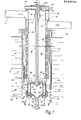
- the industrial burner shown in the figures in several embodiments is set up for heating with gaseous or liquid fuels and is used for heating the furnace space 1 of an industrial furnace, the wall of which is shown at 2 and contains a continuous opening 3 into which the burner is inserted.
- the burner itself has a cylindrical tubular casing 4 made of steel, which is surrounded by a heat insulation layer 5 and into which an air supply pipe 6 opens laterally in the area outside the furnace chamber wall 2.
- a coaxial, also made of steel air guide cylinder 7 is inserted, which is sealed at 8 on the end face against the jacket tube 4 and defines an annular space therewith, which is formed by a cylindrical wall 9 made of highly heat-resistant steel in two annular chambers 10, 11 is divided.
- the cylindrical wall 9 is connected to the cylinder jacket 4 in a gas-tight manner at 12, and its annular chamber 11 is connected to a laterally emerging exhaust gas suction line 13.
- the cylindrical wall 9 carries continuous heat exchanger ribs 14 projecting into the two annular chambers 10, 11, which together with the wall parts in between result in good heat transfer between the media flowing through the two annular channels 10, 11.
- the cylindrical wall 9 forms-along with the Martelrohr 4 and the air guide 7 has a tubular fin recuperator, thereof, of the air y relieving 7 enclosed space 15 leitz a coaxial fuel supply line 16 receives the end in a gas-tight manner with the jacket tube 4 and the Air cylinder 7 connected cover 160 is anchored contains a fuel supply line 17 opening into the fuel supply pipe 16.
- the ignition electrode arranged coaxially in the fuel supply pipe 16 is indicated at 18.
- a substantially pot-shaped ceramic combustion chamber 20 which consists of a thin-walled, high-temperature-resistant ceramic jacket and whose wall thickness is, for example, 6 mm, is arranged coaxially with the casing tube 4 and the air-guiding cylinder 7 at an axial distance 19.
- the combustion chamber 20 has a substantially cylindrical sidewall part 21, adjoins the in a transition region 22 has an end wall 23 having a nozzle-shaped constricted central outlet 24 for the g high speed of so ness from the combustion chamber 20 exit gases.
- the air guide cylinder 7 could also be protruded at the end into a residual air chamber 42, which will be explained later.
- the combustion chamber 20 is closed by an attached ceramic plate 25, which has primary air inlet openings 26 arranged evenly distributed around the central axis and is provided in the center with an opening 27 through which the fuel supply pipe 16 into the fuel inlet nozzle indicated at 28 Interior of the combustion chamber 20 protrudes.
- the fuel supply pipe 16 is supported against the ceramic plate 25 via an annular shoulder 29; it contains a bellows 30 which acts as an elastic member exerting an elastic axial force on the ceramic plate 25 and the combustion chamber 20.
- the cylindrical wall 9 of the recuperator is drawn on the end face via the air guide cylinder 7 ending at 31, specifically over the axial length of the combustion chamber 20.
- the preferred part is designated by 32; it is drawn in at the end at 33 and, with its front edge at 34, is designed to fit tightly against the outer wall of the combustion chamber.
- the nozzle openings 35 could also be provided directly in the region of the boundary 34, for example by being toothed. This enables a special cooling effect to be achieved for the combustion chamber wall.
- the drawn-in part 33 forms an annular nozzle carrier which is connected in one piece to the cylindrical wall 9 and which contains nozzle openings 35 which are distributed uniformly around the longitudinal axis of the burner and whose axes are oriented essentially parallel to the longitudinal axis of the burner.
- the nozzle carrier formed by the part 33 can have an approximately semicircular cross section or an open annular disk shape.
- the nozzle carrier could also be formed by an annular plate or disk containing the nozzle openings 35, which is connected to the extended part 32 of the cylindrical wall 9, for example welded gas-tight.
- this nozzle carrier it would also be conceivable to design this nozzle carrier as a ceramic part and to connect it at the edge to the extended part 32 of the cylindrical wall 9.
- the combustion chamber 20 is supported by the axial force exerted by the elastic member 30 against the edge of the retracted part 33 acting as a nozzle carrier, the support point being shown in FIGS. 1, 2 and 4 approximately in the manner shown in FIGS Transition area 22 lies between the cylindrical wall 21 and the end wall 23 containing the constricted outlet opening 24. In this "corner area", a flow shadow occurs in the combustion chamber 20, with the result that the local temperature load on the material of the combustion chamber 20 is lower.
- the drawn-in part 33 of the cylindrical wall 9 made of high-temperature steel is correspondingly less thermally stressed.
- the drawn-in part 33 forming the nozzle carrier is shielded by a radiation protection shield 36 which is approximately adapted to its circumference, which is at a distance from the drawn-in part 33 and the drawn-forward part 32 and at 37 covers the area of the residual air nozzle openings 35 on the end face while a cylindrical wall part 38 causes a lateral covering of the advanced part 32 of the cylindrical wall 9 up over the transition region 22 of the combustion chamber 20.
- annular exhaust gas inlet at 40 Between the insulation jacket 5 and the end of the ceramic radiation shield 36 facing the recuperator there is an annular exhaust gas inlet at 40, optionally divided into a series of discrete openings by intermediate webs, which is connected to the annular chamber 11 of the recuperator and exhausts in the Abaas indicated at 41 the furnace chamber 1 can flow.
- An annular residual air chamber 42 is delimited by the advanced and retracted parts 32 and 33 of the cylindrical wall 9 together with the outer wall of the combustion chamber 20, which concentrically surrounds the detection chamber 20 and with which from the annular chamber 1 escaping, in the recuperator preheated air is acted upon.
- the emerging air quantity is divided into the primary air quantity indicated by arrows 43, flowing into the combustion chamber 20 via the inlet openings 26, and the residual air quantity indicated by arrows 44, which flows through the residual air chamber 42 and emerges from the nozzle openings 35 in the form of residual air jets, as is the case with this is indicated at 46.
- an additional cooling device is provided in the residual air chamber 42, which is designed in the form of a cooling air ring 47, which is arranged in the vicinity of the transition area 22 and the nozzle openings 35.
- the cooling air trina 47 is connected to a cooling air supply line 48 and a cooling air discharge line 49 via lines running through the space 15; if necessary, it can have cooling air outlet openings directed towards the parts to be cooled.
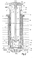
- FIG. 2 differs from that of FIG. 1 only in that a circular ceramic nozzle disc 50 is inserted on the outlet side into the ceramic combustion chamber 20, which has a number of uniformly distributed cylindrical outlet openings 51, through which the in the embodiment according to Fig. 1 emerging from the outlet 24 a main jet 53 is divided into a number of axially parallel main jets 53a.
- four cylindrical nozzle openings 51 are provided in the present case, the center points of which lie on an imaginary concentric inner circle 54 and which are surrounded by four residual air nozzle openings 35 of smaller diameter, the center points of which on an imaginary circle 55 are arranged.
- the respectively evenly distributed nozzle openings 35 and outlet openings 51 are offset from one another and arranged symmetrically to one another.
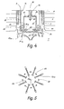
- the nozzle disk 50 according to FIG. 2 is replaced by a nozzle disk 50a, the nozzle openings 51a of which, lying on a conical jacket, are directed radially obliquely downwards, as is the case with a so-called wall jet burner.
- the residual air leading nozzle openings 35 are again with their centers on the circle 55 and are arranged symmetrically offset from the outlet openings 51a, which in turn are also arranged evenly distributed with their centers on the common circle 54 .
- the axes of the residual air nozzle openings 35 thus run transversely to the axes of the gas jets emerging from the outlet openings 51a.
- the nozzle disk 50 or 50a is placed on the edge in the manner shown in FIGS. 2, 4 on the end wall 23 of the combustion chamber 20 so that it maintains a certain radial mobility with respect to the latter.
- the burner described is operated in the on-off mode such that at the combustion chamber outlet, i.e. At the only retracted outlet opening 24 of FIG. 1 or the outlet openings 51 and 51a and at the nozzle openings 35, a gas or air outlet velocity of the order of magnitude of 100 to 150 m / s occurs, which means that a pressure drop of 1 to 2, preferably 1.5 kPa.
- the proportion of the total passage area of the residual air nozzle openings 35 in the total cross section of the outlet opening 24 or the outlet openings 51, 51a is between 10 and 50%, preferably 30%.
- the inner diameter of the combustion chamber 20 and its axial length are two to four times, preferably three times the diameter of the outlet opening 24 of the embodiment according to FIG. 1.
- the flame burns stably and quietly with the selected combustion chamber dimensions, even when starting from room temperature, which is important for on-off operation.
- the combustion chamber made of Si-infiltrated SiC withstood the temperature stress.
- the conical sealing seat on the front of the combustion chamber is particularly advantageous because it absorbs the differences in expansion between ceramic and metal.
- the cooling ring 47 and the insulation for furnace temperatures above 1100 ° C reduce the temperature in the off phases of the burner at the residual air nozzle openings 35 to the permissible maximum temperature of heat-resistant steel (approx. 1100 ° C), with only relatively small losses and the furnace atmosphere is not affected.
- the exhaust gas is extracted in a known manner from each burner via an eductor or directly.
- the burner is also suitable for indirect heating in so-called jacket radiant heaters, wherever the high flame impulse is used for the exhaust gas circulation in the jet pipe (flame pipe in jacket radiant heating pipes separated from the burner or P-pipe, W-pipe without flame pipe).
Landscapes
- Engineering & Computer Science (AREA)
- Chemical & Material Sciences (AREA)
- Combustion & Propulsion (AREA)
- Mechanical Engineering (AREA)
- General Engineering & Computer Science (AREA)
- Physics & Mathematics (AREA)
- Thermal Sciences (AREA)
- Combustion Of Fluid Fuel (AREA)
- Hydrogen, Water And Hydrids (AREA)
- Gas Burners (AREA)
- Air Supply (AREA)
Priority Applications (1)
| Application Number | Priority Date | Filing Date | Title |
|---|---|---|---|
| AT85105682T ATE39993T1 (de) | 1984-06-15 | 1985-05-09 | Industriebrenner fuer gasfoermige oder fluessige brennstoffe. |
Applications Claiming Priority (2)
| Application Number | Priority Date | Filing Date | Title |
|---|---|---|---|
| DE3422229 | 1984-06-15 | ||
| DE3422229A DE3422229C2 (de) | 1984-06-15 | 1984-06-15 | Industriebrenner für gasförmige oder flüssige Brennstoffe |
Publications (3)
| Publication Number | Publication Date |
|---|---|
| EP0164576A2 true EP0164576A2 (fr) | 1985-12-18 |
| EP0164576A3 EP0164576A3 (en) | 1987-03-04 |
| EP0164576B1 EP0164576B1 (fr) | 1989-01-11 |
Family
ID=6238413
Family Applications (1)
| Application Number | Title | Priority Date | Filing Date |
|---|---|---|---|
| EP85105682A Expired EP0164576B1 (fr) | 1984-06-15 | 1985-05-09 | Brûleur industriel pour combustibles gazeux ou liquides |
Country Status (7)
| Country | Link |
|---|---|
| US (1) | US4586894A (fr) |
| EP (1) | EP0164576B1 (fr) |
| JP (1) | JPS6149910A (fr) |
| AT (1) | ATE39993T1 (fr) |
| DD (1) | DD236577A5 (fr) |
| DE (2) | DE3422229C2 (fr) |
| SU (1) | SU1400519A3 (fr) |
Cited By (9)
| Publication number | Priority date | Publication date | Assignee | Title |
|---|---|---|---|---|
| FR2616520A1 (fr) * | 1987-06-11 | 1988-12-16 | Gaz De France | Systeme a bruleur notamment a grande vitesse de sortie des gaz brules |
| EP0440281A2 (fr) * | 1990-01-29 | 1991-08-07 | F.L. Smidth & Co. A/S | Brûleur pour combustible solide ou liquide et gazeux |
| DE4138434C1 (fr) * | 1991-11-22 | 1992-12-03 | Aichelin Gmbh, 7015 Korntal-Muenchingen, De | |
| EP0543323A2 (fr) * | 1991-11-22 | 1993-05-26 | Aichelin Gmbh | Brûleur pour fours industriels |
| EP0567865A2 (fr) * | 1992-04-25 | 1993-11-03 | HEIMSOTH VERWALTUNGEN GmbH & CO. KG Beteiligungsgesellschaft | Brûleur à récupération pour un four |
| US5513981A (en) * | 1991-11-22 | 1996-05-07 | Aichelin Gmbh | Burner with variable volume combination chamber |
| CN106257138B (zh) * | 2015-06-18 | 2019-01-11 | 勤益科技大学 | 输出热源温度可控的燃烧装置 |
| EP3604923A1 (fr) * | 2018-07-31 | 2020-02-05 | Linde Aktiengesellschaft | Système de récupération de la chaleur pour un four ayant un ou plusieurs brûleurs |
| WO2020253970A1 (fr) * | 2019-06-21 | 2020-12-24 | Econova GmbH | Brûleur pour réduire les émissions de nox et procédé permettant de faire fonctionner le brûleur |
Families Citing this family (26)
| Publication number | Priority date | Publication date | Assignee | Title |
|---|---|---|---|---|
| DE3729971A1 (de) | 1987-09-08 | 1989-03-16 | Wuenning Joachim | Heissgaserzeugungseinrichtung mit thermischer nachverbrennung |
| ATE67020T1 (de) * | 1988-01-15 | 1991-09-15 | Ws Waermeprozesstechnik Gmbh | Industriebrenner mit rekuperativer luftvorwaermung, insbesondere zur beheizung von ofenraeumen von industrieoefen. |
| CA1303477C (fr) * | 1988-06-06 | 1992-06-16 | Yoichiro Ohkubo | Dispositif de combustion catalytique |
| DE58907451D1 (de) * | 1988-10-12 | 1994-05-19 | Ruhrgas Ag | Brenner, insbesondere Hochgeschwindigkeitsbrenner. |
| DE59007772D1 (de) * | 1990-06-29 | 1995-01-05 | Wuenning Joachim | Verfahren und Vorrichtung zum Verbrennen von Brennstoff in einem Verbrennungsraum. |
| DE4026605A1 (de) * | 1990-08-23 | 1992-02-27 | Lbe Beheizungseinrichtungen | Brenner |
| DE4419332A1 (de) * | 1994-06-02 | 1995-12-14 | Wuenning Joachim | Industriebrenner mit geringer NO¶x¶-Emission |
| IT1287521B1 (it) * | 1996-12-20 | 1998-08-06 | Ipeg Spa | Bruciatore intensivo |
| DE19718878B4 (de) * | 1997-05-03 | 2005-06-30 | Lbe Feuerungstechnik Gmbh | Verfahren und Vorrichtung zur mehrstufigen Verbrennung von Brennstoff |
| US6164074A (en) * | 1997-12-12 | 2000-12-26 | United Technologies Corporation | Combustor bulkhead with improved cooling and air recirculation zone |
| DE10217524B4 (de) * | 2002-04-19 | 2005-10-13 | WS - Wärmeprozesstechnik GmbH | Brenner mit seitlichem Austritt zur flammenlosen Oxidation |
| ITMI20032327A1 (it) * | 2003-11-28 | 2005-05-29 | Techint Spa | Bruciatore a gas a basse emissioni inquinanti. |
| EP2278223A1 (fr) * | 2004-05-19 | 2011-01-26 | Innovative Energy, Inc. | Procédé et appareil de combustion |
| US7168949B2 (en) * | 2004-06-10 | 2007-01-30 | Georgia Tech Research Center | Stagnation point reverse flow combustor for a combustion system |
| US7425127B2 (en) * | 2004-06-10 | 2008-09-16 | Georgia Tech Research Corporation | Stagnation point reverse flow combustor |
| US8062027B2 (en) | 2005-08-11 | 2011-11-22 | Elster Gmbh | Industrial burner and method for operating an industrial burner |
| DE102007048487B4 (de) * | 2007-10-09 | 2009-07-30 | Ibs Industrie-Brenner-Systeme Gmbh | Brenner für einen Industrieofen |
| US8622737B2 (en) * | 2008-07-16 | 2014-01-07 | Robert S. Babington | Perforated flame tube for a liquid fuel burner |
| EP2498002B1 (fr) | 2011-03-08 | 2016-05-11 | Elster GmbH | Brûleur industriel à haute efficacité |
| WO2013096646A1 (fr) | 2011-12-20 | 2013-06-27 | Eclipse, Inc. | Procédé et appareil pour brûleur à deux modes produisant une faible émission de nox |
| RU2516671C2 (ru) * | 2012-03-29 | 2014-05-20 | Общество с ограниченной ответственностью "Союз" | Способ сжигания подстилочного помета от напольного содержания птицы и установка для осуществления способа (варианты) |
| RU2538566C1 (ru) * | 2013-06-21 | 2015-01-10 | Юрий Викторович Яковлев | Способ сжигания птичьего помета и котел для осуществления способа |
| GB2516267B (en) * | 2013-07-17 | 2016-08-17 | Edwards Ltd | Head assembly |
| FR3041742B1 (fr) * | 2015-09-30 | 2017-11-17 | Ifp Energies Now | Chambre de combustion d'une turbine, notamment d'une turbine a cycle thermodynamique avec recuperateur, pour la production d'energie, en particulier d'energie electrique. |
| DE102016111656A1 (de) | 2016-06-24 | 2017-12-28 | WS - Wärmeprozesstechnik GmbH | Brenner mit offenem Strahlrohr |
| CN108302534A (zh) * | 2017-12-11 | 2018-07-20 | 醴陵友立特种陶瓷有限公司 | 用于陶瓷窑炉的蓄热式燃烧器 |
Citations (6)
| Publication number | Priority date | Publication date | Assignee | Title |
|---|---|---|---|---|
| US3101773A (en) * | 1960-03-22 | 1963-08-27 | Selas Corp Of America | Air preheating burner |
| DE2243604A1 (de) * | 1971-10-26 | 1973-05-03 | Lausitzer Granit Demitz Thumit | Thermobrenner |
| FR2336554A1 (fr) * | 1975-12-22 | 1977-07-22 | Gen Electric | Systeme de combustion pour turbines a gaz |
| EP0029939A1 (fr) * | 1979-11-29 | 1981-06-10 | Aichelin GmbH | Brûleur industriel |
| EP0039762A1 (fr) * | 1980-05-08 | 1981-11-18 | Joachim Dr.-Ing. Wünning | Procédé pour la récupération de chaleur dans des brûleurs d'huile ou de gaz pour poêles d'industrie ou analogue et brûleurs pour cela |
| US4351632A (en) * | 1977-07-01 | 1982-09-28 | Chugairo Kogyo Kaisha Ltd. | Burner with suppressed NOx generation |
Family Cites Families (3)
| Publication number | Priority date | Publication date | Assignee | Title |
|---|---|---|---|---|
| DE1401868A1 (de) * | 1961-05-23 | 1968-10-24 | Koppers Wistra Ofenbau Gmbh | Umwaelzbrenner |
| US3386475A (en) * | 1966-03-25 | 1968-06-04 | Fletcher Co H E | Flame jet burner construction |
| US3730668A (en) * | 1971-03-03 | 1973-05-01 | Tokyo Gas Co Ltd | Combustion method of gas burners for suppressing the formation of nitrogen oxides and burner apparatus for practicing said method |
-
1984
- 1984-06-15 DE DE3422229A patent/DE3422229C2/de not_active Expired
-
1985
- 1985-05-09 DE DE8585105682T patent/DE3567531D1/de not_active Expired
- 1985-05-09 AT AT85105682T patent/ATE39993T1/de not_active IP Right Cessation
- 1985-05-09 EP EP85105682A patent/EP0164576B1/fr not_active Expired
- 1985-06-11 SU SU3905535A patent/SU1400519A3/ru active
- 1985-06-12 US US06/744,107 patent/US4586894A/en not_active Expired - Lifetime
- 1985-06-12 DD DD85277300A patent/DD236577A5/de not_active IP Right Cessation
- 1985-06-14 JP JP60128379A patent/JPS6149910A/ja not_active Expired - Lifetime
Patent Citations (6)
| Publication number | Priority date | Publication date | Assignee | Title |
|---|---|---|---|---|
| US3101773A (en) * | 1960-03-22 | 1963-08-27 | Selas Corp Of America | Air preheating burner |
| DE2243604A1 (de) * | 1971-10-26 | 1973-05-03 | Lausitzer Granit Demitz Thumit | Thermobrenner |
| FR2336554A1 (fr) * | 1975-12-22 | 1977-07-22 | Gen Electric | Systeme de combustion pour turbines a gaz |
| US4351632A (en) * | 1977-07-01 | 1982-09-28 | Chugairo Kogyo Kaisha Ltd. | Burner with suppressed NOx generation |
| EP0029939A1 (fr) * | 1979-11-29 | 1981-06-10 | Aichelin GmbH | Brûleur industriel |
| EP0039762A1 (fr) * | 1980-05-08 | 1981-11-18 | Joachim Dr.-Ing. Wünning | Procédé pour la récupération de chaleur dans des brûleurs d'huile ou de gaz pour poêles d'industrie ou analogue et brûleurs pour cela |
Cited By (21)
| Publication number | Priority date | Publication date | Assignee | Title |
|---|---|---|---|---|
| FR2616520A1 (fr) * | 1987-06-11 | 1988-12-16 | Gaz De France | Systeme a bruleur notamment a grande vitesse de sortie des gaz brules |
| EP0296032A1 (fr) * | 1987-06-11 | 1988-12-21 | Gaz De France | Système à brûleur notamment à grande vitesse de sortie des gaz brûlés |
| US4894006A (en) * | 1987-06-11 | 1990-01-16 | Gaz De France | Burner system in particular with a high velocity of the burnt gases |
| EP0440281A2 (fr) * | 1990-01-29 | 1991-08-07 | F.L. Smidth & Co. A/S | Brûleur pour combustible solide ou liquide et gazeux |
| EP0440281A3 (en) * | 1990-01-29 | 1992-01-22 | F.L. Smidth & Co. A/S | Burner for solid and liquid or gaseous fuel |
| EP0543323A2 (fr) * | 1991-11-22 | 1993-05-26 | Aichelin Gmbh | Brûleur pour fours industriels |
| US5460515A (en) * | 1991-11-22 | 1995-10-24 | Aichelin Gmbh | Burner for an industrial furnace |
| EP0543324A2 (fr) * | 1991-11-22 | 1993-05-26 | Aichelin Gmbh | Brûleur pour fours industriels |
| EP0543323A3 (en) * | 1991-11-22 | 1993-09-08 | Aichelin Gmbh | Burner for industrial furnaces |
| EP0543324A3 (en) * | 1991-11-22 | 1993-09-08 | Aichelin Gmbh | Burner for industrial furnaces |
| DE4138434C1 (fr) * | 1991-11-22 | 1992-12-03 | Aichelin Gmbh, 7015 Korntal-Muenchingen, De | |
| US5513981A (en) * | 1991-11-22 | 1996-05-07 | Aichelin Gmbh | Burner with variable volume combination chamber |
| US5344310A (en) * | 1991-11-22 | 1994-09-06 | Aichelin Gmbh | Burner for an industrial furnace |
| EP0567865A2 (fr) * | 1992-04-25 | 1993-11-03 | HEIMSOTH VERWALTUNGEN GmbH & CO. KG Beteiligungsgesellschaft | Brûleur à récupération pour un four |
| EP0567865A3 (en) * | 1992-04-25 | 1993-12-29 | Heimsoth Verwaltungen | Recuperative burner for a furnace |
| CN106257138B (zh) * | 2015-06-18 | 2019-01-11 | 勤益科技大学 | 输出热源温度可控的燃烧装置 |
| EP3604923A1 (fr) * | 2018-07-31 | 2020-02-05 | Linde Aktiengesellschaft | Système de récupération de la chaleur pour un four ayant un ou plusieurs brûleurs |
| WO2020025163A1 (fr) * | 2018-07-31 | 2020-02-06 | Linde Aktiengesellschaft | Système de récupération de chaleur pour un four pourvu d'un ou de plusieurs brûleurs |
| WO2020253970A1 (fr) * | 2019-06-21 | 2020-12-24 | Econova GmbH | Brûleur pour réduire les émissions de nox et procédé permettant de faire fonctionner le brûleur |
| CN113167467A (zh) * | 2019-06-21 | 2021-07-23 | 艾科诺瓦有限责任公司 | 用于减少NOx-排放的燃烧器和用于运行燃烧器的方法 |
| CN113167467B (zh) * | 2019-06-21 | 2024-03-08 | 艾科诺瓦有限责任公司 | 用于减少NOx-排放的燃烧器和用于运行燃烧器的方法 |
Also Published As
| Publication number | Publication date |
|---|---|
| DD236577A5 (de) | 1986-06-11 |
| ATE39993T1 (de) | 1989-01-15 |
| US4586894A (en) | 1986-05-06 |
| DE3422229A1 (de) | 1985-12-19 |
| EP0164576A3 (en) | 1987-03-04 |
| SU1400519A3 (ru) | 1988-05-30 |
| DE3567531D1 (en) | 1989-02-16 |
| EP0164576B1 (fr) | 1989-01-11 |
| JPS6149910A (ja) | 1986-03-12 |
| DE3422229C2 (de) | 1986-06-05 |
Similar Documents
| Publication | Publication Date | Title |
|---|---|---|
| EP0164576B1 (fr) | Brûleur industriel pour combustibles gazeux ou liquides | |
| DE2839703A1 (de) | Ringfoermiger doppelbrenner | |
| EP0029939B1 (fr) | Brûleur industriel | |
| DE2802640A1 (de) | Rekuperativer brenner fuer stroemende brennstoffe | |
| DE2528559C3 (de) | Vorrichtung zum Durchführen einer Reaktion zwischen Strömungen fließfähiger Medien | |
| EP0903539B1 (fr) | Brûleur avec régénérateur | |
| DE19931025C2 (de) | Rekuperator für eine Strahlrohrbrenner-Vorrichtung mit brennernaher Abgasrückführung | |
| DE3738623C2 (de) | Heizkessel mit Rauchgasrezirkulation | |
| DE4420477C2 (de) | Industriebrenner mit regenerativer Luftvorwärmung | |
| DE3131200C2 (de) | Metallheizofen | |
| DE4238529C2 (de) | Brenner zur Heißgaserzeugung | |
| DE1501970A1 (de) | Brenner fuer OEfen | |
| DE10140422C1 (de) | Thermische Nachverbrennungsvorrichtung | |
| DE2432330C2 (de) | Brenner mit hoher Austrittsgeschwindigkeit der Rauchgase | |
| EP0229231B1 (fr) | Brûleur pour la combustion de combustibles avec diminution de la formation des oxydes d'azote | |
| DE1286678B (de) | Brenner fuer gasfoermige Brennstoffe | |
| DE2053805A1 (de) | Rekuperativ-Brenner | |
| DE1551761A1 (de) | Industriebrenner mit rekuperativer Luftvorwaermung | |
| DE69311795T2 (de) | Brenner, in dem brennbare Abfälle als Brennstoff verwendet werden | |
| DE3312353C2 (de) | Kohlenstaubbrenner | |
| DE2943289A1 (de) | Brenner fuer fluessige und/oder gasfoermige brennstoffe, insbesondere fuer industrielle oefen | |
| DE2309696C3 (de) | Heizungskessel mit Umlenkkammer | |
| DE1458766C (de) | Röstvorrichtung mit einer Brennkammer zur Wärmebehandlung pulverförmiger Massen | |
| AT285795B (de) | Hochtemperaturbrenner mit radialer Flammenerweiterung | |
| DD285817A5 (de) | Hochleistungsgasbrenner |
Legal Events
| Date | Code | Title | Description |
|---|---|---|---|
| PUAI | Public reference made under article 153(3) epc to a published international application that has entered the european phase |
Free format text: ORIGINAL CODE: 0009012 |
|
| AK | Designated contracting states |
Designated state(s): AT DE FR GB IT |
|
| PUAL | Search report despatched |
Free format text: ORIGINAL CODE: 0009013 |
|
| AK | Designated contracting states |
Kind code of ref document: A3 Designated state(s): AT DE FR GB IT |
|
| 17P | Request for examination filed |
Effective date: 19870321 |
|
| 17Q | First examination report despatched |
Effective date: 19870825 |
|
| GRAA | (expected) grant |
Free format text: ORIGINAL CODE: 0009210 |
|
| AK | Designated contracting states |
Kind code of ref document: B1 Designated state(s): AT DE FR GB IT |
|
| REF | Corresponds to: |
Ref document number: 39993 Country of ref document: AT Date of ref document: 19890115 Kind code of ref document: T |
|
| ITF | It: translation for a ep patent filed | ||
| GBT | Gb: translation of ep patent filed (gb section 77(6)(a)/1977) | ||
| REF | Corresponds to: |
Ref document number: 3567531 Country of ref document: DE Date of ref document: 19890216 |
|
| ET | Fr: translation filed | ||
| PLBI | Opposition filed |
Free format text: ORIGINAL CODE: 0009260 |
|
| 26 | Opposition filed |
Opponent name: LBE BEHEIZUNGSEINRICHTUNGEN GMBH Effective date: 19891009 |
|
| PLBM | Termination of opposition procedure: date of legal effect published |
Free format text: ORIGINAL CODE: 0009276 |
|
| STAA | Information on the status of an ep patent application or granted ep patent |
Free format text: STATUS: OPPOSITION PROCEDURE CLOSED |
|
| 27C | Opposition proceedings terminated |
Effective date: 19901126 |
|
| ITTA | It: last paid annual fee | ||
| REG | Reference to a national code |
Ref country code: GB Ref legal event code: IF02 |
|
| PGFP | Annual fee paid to national office [announced via postgrant information from national office to epo] |
Ref country code: FR Payment date: 20020502 Year of fee payment: 18 Ref country code: AT Payment date: 20020502 Year of fee payment: 18 |
|
| PGFP | Annual fee paid to national office [announced via postgrant information from national office to epo] |
Ref country code: GB Payment date: 20020507 Year of fee payment: 18 |
|
| PG25 | Lapsed in a contracting state [announced via postgrant information from national office to epo] |
Ref country code: GB Free format text: LAPSE BECAUSE OF NON-PAYMENT OF DUE FEES Effective date: 20030509 Ref country code: AT Free format text: LAPSE BECAUSE OF NON-PAYMENT OF DUE FEES Effective date: 20030509 |
|
| GBPC | Gb: european patent ceased through non-payment of renewal fee |
Effective date: 20030509 |
|
| PG25 | Lapsed in a contracting state [announced via postgrant information from national office to epo] |
Ref country code: FR Free format text: LAPSE BECAUSE OF NON-PAYMENT OF DUE FEES Effective date: 20040130 |
|
| REG | Reference to a national code |
Ref country code: FR Ref legal event code: ST |
|
| PGFP | Annual fee paid to national office [announced via postgrant information from national office to epo] |
Ref country code: DE Payment date: 20040531 Year of fee payment: 20 |
|
| PLAB | Opposition data, opponent's data or that of the opponent's representative modified |
Free format text: ORIGINAL CODE: 0009299OPPO |