EP0164324B1 - Vibration insulating handle - Google Patents
Vibration insulating handle Download PDFInfo
- Publication number
- EP0164324B1 EP0164324B1 EP85850152A EP85850152A EP0164324B1 EP 0164324 B1 EP0164324 B1 EP 0164324B1 EP 85850152 A EP85850152 A EP 85850152A EP 85850152 A EP85850152 A EP 85850152A EP 0164324 B1 EP0164324 B1 EP 0164324B1
- Authority
- EP
- European Patent Office
- Prior art keywords
- tool housing
- slots
- handle
- outer tube
- tool
- Prior art date
- Legal status (The legal status is an assumption and is not a legal conclusion. Google has not performed a legal analysis and makes no representation as to the accuracy of the status listed.)
- Expired - Lifetime
Links
- 230000003584 silencer Effects 0.000 claims description 4
- 238000005452 bending Methods 0.000 claims description 3
- 238000010008 shearing Methods 0.000 claims description 3
- 238000004519 manufacturing process Methods 0.000 description 1
Images
Classifications
-
- B—PERFORMING OPERATIONS; TRANSPORTING
- B25—HAND TOOLS; PORTABLE POWER-DRIVEN TOOLS; MANIPULATORS
- B25F—COMBINATION OR MULTI-PURPOSE TOOLS NOT OTHERWISE PROVIDED FOR; DETAILS OR COMPONENTS OF PORTABLE POWER-DRIVEN TOOLS NOT PARTICULARLY RELATED TO THE OPERATIONS PERFORMED AND NOT OTHERWISE PROVIDED FOR
- B25F5/00—Details or components of portable power-driven tools not particularly related to the operations performed and not otherwise provided for
- B25F5/02—Construction of casings, bodies or handles
- B25F5/025—Construction of casings, bodies or handles with torque reaction bars for rotary tools
- B25F5/026—Construction of casings, bodies or handles with torque reaction bars for rotary tools in the form of an auxiliary handle
-
- B—PERFORMING OPERATIONS; TRANSPORTING
- B25—HAND TOOLS; PORTABLE POWER-DRIVEN TOOLS; MANIPULATORS
- B25F—COMBINATION OR MULTI-PURPOSE TOOLS NOT OTHERWISE PROVIDED FOR; DETAILS OR COMPONENTS OF PORTABLE POWER-DRIVEN TOOLS NOT PARTICULARLY RELATED TO THE OPERATIONS PERFORMED AND NOT OTHERWISE PROVIDED FOR
- B25F5/00—Details or components of portable power-driven tools not particularly related to the operations performed and not otherwise provided for
- B25F5/006—Vibration damping means
-
- Y—GENERAL TAGGING OF NEW TECHNOLOGICAL DEVELOPMENTS; GENERAL TAGGING OF CROSS-SECTIONAL TECHNOLOGIES SPANNING OVER SEVERAL SECTIONS OF THE IPC; TECHNICAL SUBJECTS COVERED BY FORMER USPC CROSS-REFERENCE ART COLLECTIONS [XRACs] AND DIGESTS
- Y10—TECHNICAL SUBJECTS COVERED BY FORMER USPC
- Y10S—TECHNICAL SUBJECTS COVERED BY FORMER USPC CROSS-REFERENCE ART COLLECTIONS [XRACs] AND DIGESTS
- Y10S173/00—Tool driving or impacting
- Y10S173/02—Sound muffling
-
- Y—GENERAL TAGGING OF NEW TECHNOLOGICAL DEVELOPMENTS; GENERAL TAGGING OF CROSS-SECTIONAL TECHNOLOGIES SPANNING OVER SEVERAL SECTIONS OF THE IPC; TECHNICAL SUBJECTS COVERED BY FORMER USPC CROSS-REFERENCE ART COLLECTIONS [XRACs] AND DIGESTS
- Y10—TECHNICAL SUBJECTS COVERED BY FORMER USPC
- Y10T—TECHNICAL SUBJECTS COVERED BY FORMER US CLASSIFICATION
- Y10T74/00—Machine element or mechanism
- Y10T74/20—Control lever and linkage systems
- Y10T74/20576—Elements
- Y10T74/20732—Handles
- Y10T74/2078—Handle bars
- Y10T74/20828—Handholds and grips
Definitions
- This invention relates to a vibration insulating handle for a pneumatic power tool.
- the invention concerns a vibration insulating power tool handle comprising an inner tube rigidly attached at its one end to the tool housing and forming an air communication passage, an outer tube rigidly attached at its one end to the tool housing and surrounding in a coaxial relationship said inner tube, said tubes being interconnected at their tool housing opposite ends and being radially spaced from each other over a substantial part of their length.
- a tool handle of this type is described in EP-A-0 136 278, claiming priority from August 16, 1983 and falling within the terms of Article 54, paragraph 3, EPC.
- the main object of the invention is to accomplish a vibration insulating power tool handle of the above type without causing a substantial increase in the manufacturing costs of the handle and without impairing the manoeuverability of the tool.
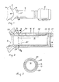
- the handle illustrated in the drawing figures is attached to the housing 10 of a pneumatic power tool and carries at its tool housing opposite end a silencer 12.
- the latter communicates with the outlet side of the pneumatic motor of the tool (not shown) via a longitudinal exhaust passage 13 extending through the handle.
- the exhaust passage 13 is defined by an inner tube 15 which is surrounded by an outer tube 16. At their one ends, to the left in Figs. 1 and 2, the tubes 15, 16 are rigidly attached to the tool housing 10.
- the handle For angular adjustment of the handle relative to the tool housing 10 the latter is formed with a part- cylindrical mounting surface 17, see Fig. 1, whereas the handle has a contact surface 18 of the same radius.
- the handle is locked to the tool housing 10 in desired positions by a clamping means (not shown).
- the clamping means engages the outer tube 16, and by means of a shoulder 19 in the outer tube 16 and a flange 20 on the inner tube 15 the latter is firmly clamped against the mounting surface 17 on the tool housing 10.
- the tubes 15,16 are radially spaced from each other, thereby forming an annular heat insulating gap 22.
- Adjacent its tool housing opposite end, the outer tube 16 Adjacent its tool housing opposite end, the outer tube 16 has an internal waist 23 for radial support of the inner tube 15.
- the extreme end of the outer tube 16 forms a socket 24 in which a neck portion 25 of the silencer 12 is received.
- the silencer 12 is locked to the outer tube 16 by means of a transverse pin 26.
- the outertube 16 Adjacent the tool housing 10,the outertube 16 is provided with four peripherally extending slots 27, 28. These slots 27, 28 are disposed in pairs in two axially spaced planes, and the slots 27 of one of these pairs are located so as to overlap the slots 28 in the other pair. Each of the slots 27, 28 covers more than 90 degrees of the circumference of the tube 16. (See Fig. 3).
- the purpose of the slots 27, 28 is to accomplish a weakened portion 30 of the outer tube 16 adjacent the tool housing end of the latter.
- This weakened portion 30 makes the outer tube 16 yield elastically to bending and shearing vibration forces transmitted to the handle during operation of the tool, which means that a substantial part of the outer tube 16 moves radially relative to the inner tube 15 in response to the vibrations occuring in the latter.
- the type of pattern according to which the slots 27, 28 are disposed is advantageous in that the outer tube 16 is rendered weak as regards bending and shearing forces but remains stiff as regards torsional loads. This is important, because handle weakness as regards torsional load would seriously impair the manoeuverability of the tool. It is also important to adapt the characteristics of the slotted weakened portion 30 to the dimensions and material characteristics of the outer tube 16 such that the resonance frequency of the outer tube 16 is lower than the frequency of the vibrations transmitted from the tool housing 20.
- the weakened portion 30 is accomplished by two pairs of slots 27, 28 arranged in two axially spaced rows.
- the invention is not limited to this particular design, but may be freely varied within the scope of the claims.
- the slots in each row may be shorter and more than two in number, and there may be more than two rows.
Applications Claiming Priority (2)
| Application Number | Priority Date | Filing Date | Title |
|---|---|---|---|
| SE8402446 | 1984-05-07 | ||
| SE8402446A SE442963B (sv) | 1984-05-07 | 1984-05-07 | Vibrationsisolerande handtag |
Publications (3)
| Publication Number | Publication Date |
|---|---|
| EP0164324A2 EP0164324A2 (en) | 1985-12-11 |
| EP0164324A3 EP0164324A3 (en) | 1987-06-24 |
| EP0164324B1 true EP0164324B1 (en) | 1990-08-08 |
Family
ID=20355776
Family Applications (1)
| Application Number | Title | Priority Date | Filing Date |
|---|---|---|---|
| EP85850152A Expired - Lifetime EP0164324B1 (en) | 1984-05-07 | 1985-05-02 | Vibration insulating handle |
Country Status (5)
| Country | Link |
|---|---|
| US (1) | US4611671A (sv) |
| EP (1) | EP0164324B1 (sv) |
| JP (1) | JPS6114868A (sv) |
| DE (1) | DE3579047D1 (sv) |
| SE (1) | SE442963B (sv) |
Cited By (1)
| Publication number | Priority date | Publication date | Assignee | Title |
|---|---|---|---|---|
| CN103982281A (zh) * | 2014-05-30 | 2014-08-13 | 清华大学苏州汽车研究院(相城) | 一种用于汽车排气系统的主动噪声控制系统及其控制方法 |
Families Citing this family (40)
| Publication number | Priority date | Publication date | Assignee | Title |
|---|---|---|---|---|
| US5125286A (en) * | 1991-02-19 | 1992-06-30 | Ken Wilson | Handlebar handgrip |
| JPH0829258B2 (ja) * | 1993-04-16 | 1996-03-27 | 株式会社細川製作所 | 籾すり精米機の脱ぷファン装置 |
| US5453577A (en) * | 1994-01-11 | 1995-09-26 | Chicago Pneumatic Tool Company | Pneumatic tool and vibration isolator mounts therefor |
| US5697456A (en) * | 1995-04-10 | 1997-12-16 | Milwaukee Electric Tool Corp. | Power tool with vibration isolated handle |
| US5708244A (en) * | 1995-10-19 | 1998-01-13 | Conti; William S. | Handgrip switch assembly |
| AU1467997A (en) * | 1996-01-11 | 1997-08-01 | Chicago Pneumatic Tool Company | A pneumatic tool and vibration isolator mounts therefor |
| DE29711559U1 (de) * | 1997-07-02 | 1997-08-21 | Howmedica Gmbh | Längliches Element zur Übertragung von Kräften |
| US6026910A (en) * | 1998-01-13 | 2000-02-22 | Chicago Pneumatic Tool Company | Power tool and vibration isolator therefor |
| US5992540A (en) * | 1998-03-06 | 1999-11-30 | Snap-On Tools Company | Air ratchet hand tool with thermoplastic jacket |
| SE520071C2 (sv) * | 1998-08-20 | 2003-05-20 | Atlas Copco Tools Ab | Portabelt kraftverktyg med värmeavskärmande organ |
| WO2000076731A1 (en) * | 1999-06-10 | 2000-12-21 | Macdonald Air Tools Limited | Pneumatic tool |
| US6173500B1 (en) | 1999-08-13 | 2001-01-16 | S-B Power Tool Company | Sealing plug as part of a rubber boot |
| JP4537594B2 (ja) * | 2001-02-07 | 2010-09-01 | 本田技研工業株式会社 | 刈払機 |
| CN2537524Y (zh) * | 2002-04-30 | 2003-02-26 | 苏州宝时得电动工具有限公司 | 带有至少一个手柄的电动工具机 |
| GB2402098B (en) * | 2003-05-21 | 2007-10-17 | Black & Decker Inc | Vibration reduction apparatus for power tool and power tool incorporating such apparatus |
| GB2407789A (en) * | 2003-11-04 | 2005-05-11 | Black & Decker Inc | Vibration reduction apparatus for a power tool |
| GB2407791A (en) * | 2003-11-04 | 2005-05-11 | Black & Decker Inc | Vibration reduction apparatus for a power tool |
| GB2407790A (en) * | 2003-11-04 | 2005-05-11 | Black & Decker Inc | Vibration reduction apparatus for a power tool |
| SE526406C2 (sv) * | 2004-01-14 | 2005-09-06 | Silvent Ab | Ljuddämpare för pneumatiska maskiner |
| GB2414702A (en) * | 2004-06-04 | 2005-12-07 | Black & Decker Inc | Vibration Reduction Apparatus for Power Tool |
| US7676890B2 (en) | 2005-10-25 | 2010-03-16 | Black And Decker, Inc. | Vibration dampening handle for a powered apparatus |
| US8756766B2 (en) * | 2005-10-25 | 2014-06-24 | Black & Decker Inc. | Vibration dampening handle for a powered apparatus |
| JP4925657B2 (ja) * | 2005-12-14 | 2012-05-09 | ヤマハ発動機株式会社 | 車両用ハンドル及び車両 |
| DE102005062883A1 (de) * | 2005-12-29 | 2007-07-05 | Robert Bosch Gmbh | Schwingungsreduktion bei Elektrowerkzeugen |
| EP1867443B1 (de) * | 2006-06-14 | 2009-07-15 | AEG Electric Tools GmbH | Zusatzhandgriff einer handgeführten Werkzeugmaschine |
| DE102006027774A1 (de) * | 2006-06-16 | 2007-12-20 | Robert Bosch Gmbh | Handwerkzeugmaschine |
| DE102007000408A1 (de) * | 2007-07-27 | 2009-01-29 | Hilti Aktiengesellschaft | Handwerkzeuggerät |
| DE102007037047A1 (de) * | 2007-08-06 | 2009-02-12 | Robert Bosch Gmbh | Zusatzhandgriffvorrichtung |
| DE102007062722A1 (de) * | 2007-12-27 | 2009-07-02 | Robert Bosch Gmbh | Zusatzhandgriffvorrichtung |
| EP2123406B1 (de) * | 2008-05-19 | 2011-12-21 | AEG Electric Tools GmbH | Vibrationsgedämpfter Halter für Zusatzhandgriff |
| EP2161106A1 (en) * | 2008-09-07 | 2010-03-10 | Josef Kihlberg AB | Fastener driving tool with a handle portion |
| DE102009002463A1 (de) * | 2009-04-17 | 2010-10-21 | Hilti Aktiengesellschaft | Seitenhandgriff |
| GB2471141A (en) * | 2009-06-19 | 2010-12-22 | John-Paul Mcconville | Vibration-reducing handle cover |
| DE102009029626B4 (de) | 2009-09-21 | 2020-04-23 | Robert Bosch Gmbh | Handwerkzeugmaschine |
| US8484806B2 (en) | 2010-09-28 | 2013-07-16 | Boyesen Engineering | Ergonomic hand grip |
| DE102011078376A1 (de) * | 2011-06-30 | 2013-01-03 | Robert Bosch Gmbh | Handgriffvorrichtung, insbesondere für Handwerkzeuge |
| US8966773B2 (en) | 2012-07-06 | 2015-03-03 | Techtronic Power Tools Technology Limited | Power tool including an anti-vibration handle |
| US9939072B2 (en) * | 2014-09-19 | 2018-04-10 | Engineered Controls International, Llc | Noise reduction relief valve for cryogenic liquid containers |
| US10272559B2 (en) | 2014-11-12 | 2019-04-30 | Black & Decker Inc. | Side handle |
| CN107097184B (zh) * | 2016-02-19 | 2021-08-31 | 株式会社牧田 | 作业工具 |
Family Cites Families (14)
| Publication number | Priority date | Publication date | Assignee | Title |
|---|---|---|---|---|
| BE353934A (sv) * | 1927-09-16 | |||
| US2101869A (en) * | 1934-11-27 | 1937-12-14 | Sullivan Machinery Co | Vibration reducing means |
| FR933451A (fr) * | 1946-08-28 | 1948-04-22 | Perfectionnements aux poignées de cycles et motocycles | |
| NL6408413A (sv) * | 1964-07-23 | 1966-01-24 | ||
| US3344684A (en) * | 1965-10-05 | 1967-10-03 | Steere Entpr Inc | Grip |
| US3680376A (en) * | 1970-07-30 | 1972-08-01 | Foxboro Co | Low noise primary device for fluid flow measurement by head meter (signal noise) |
| FR2271452A1 (en) * | 1974-05-13 | 1975-12-12 | Pean Pierre | Flexible coupling element - is formed by sets of circumferential slots in wall of tubular piece |
| USRE29402E (en) * | 1974-05-15 | 1977-09-20 | Caterpillar Tractor Co. | Vibration isolating grip for pneumatic hand tools |
| SE409223C (sv) * | 1977-01-21 | 1980-10-02 | Atlas Copco Ab | Ventilanordning for dempning av avloppsljudet fran en tryckluftsdriven motor |
| SE7806611L (sv) * | 1978-06-06 | 1979-12-07 | Atlas Copco Ab | Ljuddempare |
| JPS6044530B2 (ja) * | 1980-03-13 | 1985-10-04 | 正治 窪川 | 振動機器の防振緩衝把手 |
| SE438465B (sv) * | 1980-12-18 | 1985-04-22 | Atlas Copco Ab | Grepporgan med valfri instellning for slagverktyg |
| SE8107226L (sv) * | 1981-01-28 | 1982-07-29 | Byggergonomilaboratoriet Hb | Vibrationsdempande anordning |
| SE446698B (sv) * | 1983-09-16 | 1986-10-06 | Atlas Copco Ab | "handhallet maskinverktyg innefattande ett motorhus och tva pa huset monterade handtag av vilka atminstone det ena er instellbart anordnat" |
-
1984
- 1984-05-07 SE SE8402446A patent/SE442963B/sv not_active IP Right Cessation
-
1985
- 1985-05-02 EP EP85850152A patent/EP0164324B1/en not_active Expired - Lifetime
- 1985-05-02 DE DE8585850152T patent/DE3579047D1/de not_active Expired - Lifetime
- 1985-05-07 US US06/731,528 patent/US4611671A/en not_active Expired - Fee Related
- 1985-05-07 JP JP60095689A patent/JPS6114868A/ja active Pending
Cited By (1)
| Publication number | Priority date | Publication date | Assignee | Title |
|---|---|---|---|---|
| CN103982281A (zh) * | 2014-05-30 | 2014-08-13 | 清华大学苏州汽车研究院(相城) | 一种用于汽车排气系统的主动噪声控制系统及其控制方法 |
Also Published As
| Publication number | Publication date |
|---|---|
| EP0164324A3 (en) | 1987-06-24 |
| DE3579047D1 (de) | 1990-09-13 |
| JPS6114868A (ja) | 1986-01-23 |
| SE8402446D0 (sv) | 1984-05-07 |
| SE8402446L (sv) | 1985-11-08 |
| SE442963B (sv) | 1986-02-10 |
| US4611671A (en) | 1986-09-16 |
| EP0164324A2 (en) | 1985-12-11 |
Similar Documents
| Publication | Publication Date | Title |
|---|---|---|
| EP0164324B1 (en) | Vibration insulating handle | |
| EP0490850B1 (en) | Vibration insulated power tool handle | |
| US20030085632A1 (en) | Spindle structure in ultrasonic machine and supporting horn used in the same | |
| CA2361103C (en) | Stator ring ventilation assembly | |
| US5719457A (en) | Squirrel-cage rotor for an asynchronous machine | |
| US4581206A (en) | Catalytic converter | |
| US4925634A (en) | Catalytic converter for use with internal combustion engine | |
| US20080206049A1 (en) | Blade angle setting for a turbomachine | |
| US4759526A (en) | Dynamoelectric machine mounting assembly | |
| US4074914A (en) | High pressure lightweight flanges | |
| US3977212A (en) | Flexible coupling | |
| GB2287073A (en) | Mounting clamp on protective bellows | |
| CA1279788C (en) | Structure for mounting flow guiding blades in ventilating port | |
| US4043030A (en) | Process for preparing distribution rotor | |
| CZ294280B6 (cs) | Demontážní zařízení | |
| US4130812A (en) | Band pass electromechanical filters | |
| JP2511151Y2 (ja) | ベロ―ズを形成するための複数のベロ―ズ部材 | |
| AU624970B2 (en) | Spacer for an essentially cylindrical tool and process for its production | |
| CA1049300A (en) | Method and a device for welding cylindrical elements to one another | |
| EP0420243A1 (en) | Ceramic stator blade unit | |
| CN214212743U (zh) | 一种方轴部件焊接夹具 | |
| US4759231A (en) | Steering wheel core structure | |
| GB2171472A (en) | Clutch cover | |
| RU1780942C (ru) | Сборна торцова фреза | |
| US4020886A (en) | Tire chain for tractors and the like |
Legal Events
| Date | Code | Title | Description |
|---|---|---|---|
| PUAI | Public reference made under article 153(3) epc to a published international application that has entered the european phase |
Free format text: ORIGINAL CODE: 0009012 |
|
| AK | Designated contracting states |
Designated state(s): DE FR GB IT |
|
| PUAL | Search report despatched |
Free format text: ORIGINAL CODE: 0009013 |
|
| AK | Designated contracting states |
Kind code of ref document: A3 Designated state(s): DE FR GB IT |
|
| 17P | Request for examination filed |
Effective date: 19871222 |
|
| 17Q | First examination report despatched |
Effective date: 19890222 |
|
| ITF | It: translation for a ep patent filed |
Owner name: BARZANO' E ZANARDO ROMA S.P.A. |
|
| GRAA | (expected) grant |
Free format text: ORIGINAL CODE: 0009210 |
|
| AK | Designated contracting states |
Kind code of ref document: B1 Designated state(s): DE FR GB IT |
|
| REF | Corresponds to: |
Ref document number: 3579047 Country of ref document: DE Date of ref document: 19900913 |
|
| ET | Fr: translation filed | ||
| PG25 | Lapsed in a contracting state [announced via postgrant information from national office to epo] |
Ref country code: GB Effective date: 19910502 |
|
| PLBE | No opposition filed within time limit |
Free format text: ORIGINAL CODE: 0009261 |
|
| STAA | Information on the status of an ep patent application or granted ep patent |
Free format text: STATUS: NO OPPOSITION FILED WITHIN TIME LIMIT |
|
| 26N | No opposition filed | ||
| GBPC | Gb: european patent ceased through non-payment of renewal fee | ||
| PG25 | Lapsed in a contracting state [announced via postgrant information from national office to epo] |
Ref country code: FR Effective date: 19920131 |
|
| PG25 | Lapsed in a contracting state [announced via postgrant information from national office to epo] |
Ref country code: DE Effective date: 19920303 |
|
| REG | Reference to a national code |
Ref country code: FR Ref legal event code: ST |