EP0162758A1 - Box from a pile of boxes forming the side wall of a building in the earth, especially a cellar - Google Patents
Box from a pile of boxes forming the side wall of a building in the earth, especially a cellar Download PDFInfo
- Publication number
- EP0162758A1 EP0162758A1 EP85400806A EP85400806A EP0162758A1 EP 0162758 A1 EP0162758 A1 EP 0162758A1 EP 85400806 A EP85400806 A EP 85400806A EP 85400806 A EP85400806 A EP 85400806A EP 0162758 A1 EP0162758 A1 EP 0162758A1
- Authority
- EP
- European Patent Office
- Prior art keywords
- box
- shape
- walls
- forming
- vertical
- Prior art date
- Legal status (The legal status is an assumption and is not a legal conclusion. Google has not performed a legal analysis and makes no representation as to the accuracy of the status listed.)
- Granted
Links
- 239000004567 concrete Substances 0.000 claims description 4
- 230000002093 peripheral effect Effects 0.000 claims description 3
- 238000004519 manufacturing process Methods 0.000 description 10
- 238000003860 storage Methods 0.000 description 3
- 238000009412 basement excavation Methods 0.000 description 2
- 238000000034 method Methods 0.000 description 2
- 239000011150 reinforced concrete Substances 0.000 description 2
- 241000897276 Termes Species 0.000 description 1
- 238000010276 construction Methods 0.000 description 1
- 238000005520 cutting process Methods 0.000 description 1
- 238000000465 moulding Methods 0.000 description 1
- 238000003825 pressing Methods 0.000 description 1
- 230000000284 resting effect Effects 0.000 description 1
- 239000004576 sand Substances 0.000 description 1
Images

Classifications
-
- E—FIXED CONSTRUCTIONS
- E04—BUILDING
- E04B—GENERAL BUILDING CONSTRUCTIONS; WALLS, e.g. PARTITIONS; ROOFS; FLOORS; CEILINGS; INSULATION OR OTHER PROTECTION OF BUILDINGS
- E04B1/00—Constructions in general; Structures which are not restricted either to walls, e.g. partitions, or floors or ceilings or roofs
- E04B1/0007—Base structures; Cellars
- E04B1/0015—Cellars constructed from prefabricated units
Definitions
- the present invention relates to a box of at least one stack of boxes constituting the side walls of a buried room, such as in particular a cellar.
- the known method comprises in particular the operations consisting in cutting out in said slabs an opening through which an excavation is dug, in installing a waterproof envelope or pocket lining said excavation, in making a raft, in particular based on sand, then a floor, side walls consisting in particular of stacked boxes, preferably prefabricated, in particular of concrete, and forming storage compartments, and a ceiling.
- posts or uprights are erected, in particular in reinforced concrete, extending from the floor to the level of the ceiling, and the structural elements of the walls are inserted, by sliding between said posts forming a support and guide slide. said boxes, by stacking them.
- the caissons playing the role of retaining walls to contain the thrust of the land by leaning against the aforementioned posts, are in particular of substantially parallelepiped shape and are open, entirely or partially, at least on their bottom faces and internal vertical side, that is to say the face opening onto the internal free space of the room.
- the object of the present invention is to eliminate the above drawbacks.
- the present invention provides a box of a stack of boxes, in particular prefabricated concrete, playing the role of retaining walls pour.conussi the thrust of the land by bearing against poles or uprights extending from the floor to the level from the ceiling of a buried room, such as in particular a cellar, said box having in particular a substantially rectangular parallelepiped shape, being open, entirely or partially, at least on its bottom faces and internal vertical side, said box being characterized in that it is formed of modular elements comprising at least one part with vertical walls in the shape of a U at right angles, and whose internal peripheral surface is in the form of a draft, and a part forming the upper face of the box nestable in the U-shaped part.
- the aforementioned box comprises a second part with vertical U-shaped walls, identical to the first U-shaped part mentioned above superimposed on said second part.
- the above-mentioned nestable part is in the form of a cover having a rim of shape conjugated to the U-shape, at the level of the bearing surface of the cover, of the aforementioned first part.
- the box 8 also consists of a part 83 forming the upper face of the box and in the form of a cover which can be fitted into the U-shaped part 81.
- the part 83 in the form of a cover includes an edge horizontal device 83a in U coming to bear on the upper edges of greater width of the part 81 and an internal rim 83b connecting to the edge 83a and having a shape conjugated to the U shape, at the bearing surface ( or larger upper edge of part 81) of part 83, of part 81.
- the vertical edges 81d; 82d of walls 81a, 81c; 82a, 82c of the respective branches of the U-shaped parts 81; 82 and the vertical edges 83c, produced at the two opposite corners situated on the same length of the cover portion 83, are aligned when the modular elements 81, 82 and 83 are assembled and bear against the posts 13, the vertical edges 81d, 82d and 83c having a shape combined with that of said posts.
- the present invention is not limited to the production of a box comprising the two modular elements 81 and 82.
- Other modular elements of identical shape to the elements 81, 82 can be superimposed so as to define a space for storage of a desired height.
- each box 8 can be undertaken continuously instead of being carried out deferred as was the case with the old form of mold, the investment in mold is therefore very limited and the production rate is very significantly increased, which considerably reduces the unit production price.
Landscapes
- Engineering & Computer Science (AREA)
- Architecture (AREA)
- Physics & Mathematics (AREA)
- Electromagnetism (AREA)
- Civil Engineering (AREA)
- Structural Engineering (AREA)
- Assembled Shelves (AREA)
- Underground Structures, Protecting, Testing And Restoring Foundations (AREA)
Abstract
La présente invention concerne une structure de caisson destiné à faire partie d'un empilement de caissons constituant les parois latérales d'un local enterré, tel que notamment une cave. Selon l'invention, chaque caisson (8) est formé d'éléments modulaires (81; 82; 83) comprenant au moins une partie (81) à parois verticales (81a, 81b, 81c) en forme de U et une partie (83) formant face supérieure du caisson emboîtable dans la partie (81) en forme de U. La présente invention s'applique notamment à l'industrie du bâtiment.The present invention relates to a box structure intended to be part of a stack of boxes constituting the side walls of a buried room, such as in particular a cellar. According to the invention, each box (8) is formed of modular elements (81; 82; 83) comprising at least one part (81) with vertical walls (81a, 81b, 81c) in the shape of a U and a part (83 ) forming the upper face of the box which fits into the U-shaped part (81). The present invention applies in particular to the building industry.
Description
La présente invention a pour objet un caisson d'au moins un empilement de caissons constituant les parois latérales d'un local enterré, tel que notamment une cave.The present invention relates to a box of at least one stack of boxes constituting the side walls of a buried room, such as in particular a cellar.
On connaît un procédé pour l'aménagement d'un local enterré, tel que notamment une cave dans une construction comportant une dalle de plancher, notamment en béton, par laquelle elle repose sur le sol. Le procédé connu comprend notamment les opérations consistant à découper dans lesdites dalles une ouverture à travers laquelle on creuse une excavation, à installer une enveloppe ou poche étanche tapissant ladite excavation, à réaliser un radier, notamment à base de sable, puis un plancher, des parois latérales constituées notamment de caissons empilés, de préférence préfabriqués, notamment en béton, et formant casiers de rangement, et un plafond. Après réalisation du plancher, on érige des poteaux ou montants notamment en béton armé, s'étendant du plancher au niveau du plafond et on insère, en glissant entre lesdits poteaux formant glissière de maintien et de guidage, les éléments de structure des parois, notamment lesdits caissons, en les empilant.A method is known for fitting out a buried room, such as in particular a cellar in a construction comprising a floor slab, in particular of concrete, by which it rests on the ground. The known method comprises in particular the operations consisting in cutting out in said slabs an opening through which an excavation is dug, in installing a waterproof envelope or pocket lining said excavation, in making a raft, in particular based on sand, then a floor, side walls consisting in particular of stacked boxes, preferably prefabricated, in particular of concrete, and forming storage compartments, and a ceiling. After completion of the floor, posts or uprights are erected, in particular in reinforced concrete, extending from the floor to the level of the ceiling, and the structural elements of the walls are inserted, by sliding between said posts forming a support and guide slide. said boxes, by stacking them.
Les caissons, jouant le rôle de murs de soutènement pour contenir la poussée des terres en prenant appui contre les poteaux précités, sont notamment de forme sensiblement parallélépipédique et sont ouverts, entièrement ou partiellement, au moins sur leurs faces de fond et latérale verticale interne, c'est-à-dire la face ouvrant sur l'espace libre interne du local.The caissons, playing the role of retaining walls to contain the thrust of the land by leaning against the aforementioned posts, are in particular of substantially parallelepiped shape and are open, entirely or partially, at least on their bottom faces and internal vertical side, that is to say the face opening onto the internal free space of the room.
Cependant, la fabrication par moulage de ces caissons coûte relativement cher car il est nécessaire de prévoir au moins deux moules différents, l'un pour la fabrication des caissons les plus inférieurs formant le soubassement des parois du local et dépourvus de paroi supérieure, l'autre pour la fabrication des caissons droits autres que ceux du soubassement, dépourvus de fond, et ayant une face supérieure jouant le rôle de fond du caisson immédiatement supérieur.However, the manufacture by molding of these casings is relatively expensive since it is necessary to provide at least two different molds, one for the manufacture of the lower casings forming the base of the walls of the room and devoid of the upper wall, the other for the manufacture of straight caissons other than those of the base, devoid of bottom, and having an upper face playing the role of bottom of the immediately upper box.
De plus, la structure des caissons connus ne permet pas de prévoir des casiers à différents espaces de rangement prédéterminés. Il faudrait pour cela prévoir autant de moules que de caissons différents, ce qui augmenterait considérablement leurs coûts de fabrication.In addition, the structure of known boxes does not allow to provide lockers with different predetermined storage spaces. This would require providing as many molds as different boxes, which would significantly increase their manufacturing costs.
La présente invention a pour but d'éliminer les inconvénients ci-dessus.The object of the present invention is to eliminate the above drawbacks.
Pour cela, la présente invention propose un caisson d'un empilement de caissons, notamment préfabriqués en béton, jouant le rôle de murs de soutènement pour.contenir la poussée des terres en prenant appui contre des poteaux ou montants s'étendant du plancher au niveau du plafond d'un local enterré, tel que notamment une cave, ledit caisson présentant notamment une forme sensiblement parallélépipédique rectangulaire, étant ouvert, entièrement ou partiellement, au moins sur ses faces de fond et latérale verticale interne, ledit caisson étant caractérisé en ce qu'il est formé d'éléments modulaires comprenant au moins une partie à parois verticales en forme de U à angles droits, et dont la surface périphérique interne est en forme de dépouille, et une partie formant face supérieure du caisson emboîtable dans la partie en forme de U.For this, the present invention provides a box of a stack of boxes, in particular prefabricated concrete, playing the role of retaining walls pour.contenir the thrust of the land by bearing against poles or uprights extending from the floor to the level from the ceiling of a buried room, such as in particular a cellar, said box having in particular a substantially rectangular parallelepiped shape, being open, entirely or partially, at least on its bottom faces and internal vertical side, said box being characterized in that it is formed of modular elements comprising at least one part with vertical walls in the shape of a U at right angles, and whose internal peripheral surface is in the form of a draft, and a part forming the upper face of the box nestable in the U-shaped part.
Selon une autre caractéristique de l'invention, le caisson précité comprend une deuxième partie à parois verticales en forme de U, identique à la première partie en forme de U précitée se superposant à ladite deuxième partie.According to another characteristic of the invention, the aforementioned box comprises a second part with vertical U-shaped walls, identical to the first U-shaped part mentioned above superimposed on said second part.
Selon encore une autre caractéristique de l'invention, la partie emboitable précitée est en forme de couvercle ayant un rebord de forme conjuguée à la forme en U, au niveau de la surface d'appui du couvercle, de la première partie précitée.According to yet another characteristic of the invention, the above-mentioned nestable part is in the form of a cover having a rim of shape conjugated to the U-shape, at the level of the bearing surface of the cover, of the aforementioned first part.
L'invention sera mieux comprise, et d'autres buts, caractéristiques, détails et avantages de celle-ci apparaîtront plus clairement au cours de la description explicative qui va suivre faite en référence aux dessins schématiques annexés donnés uniquement à titre d'exemple illustrant un mode de réalisation de l'invention, et dans lesquels :
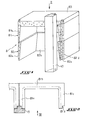
- La figure 1 est une vue en perspective d'un caisson faisant l'objet de l'invention.
- La figure 2 est une vue de dessus suivant la flèche II de la figure 1 avec section partielle, la partie formant face supérieure du caisson étant enlevée.
- La figure 3 est une vue de face suivant la flèche III de la figure 2 d'un élément modulaire du caisson,le poteau formant glissière étant enlevé.
- La figure 4 est une vue de face à partir de la figure 1 de la partie formant face supérieure du caisson ; et
- La figure 5 est une vue de dessus suivant la flèche V de la figure 4.
- Le
caisson 8 représenté en figure 1 fait partie d'un empilement de caissons qui joue le rôle de murs de soutènement pour contenir la poussée des terres en prenant appui contre les poteaux oumontants 13, notamment en béton armé, s'étendant du plancher au niveau du plafond du local enterré (non représenté), tel que notamment une cave. - Le
caisson 8, qui présente notamment une forme sensiblement parallèlépipédique rectangulaire et ouvert, entièrement ou partiellement, au moins sur ses faces de fond et latérale verticale interne,est réalisé en éléments modulaires comprenant unepartie 81 à parois verticales 81a , 81b et 81c formant un U à angles droits, uneautre partie 82 à parois verticales 82a, 82b et 82c en forme de U à angles droits et d'une structure identique à celle de lapartie 81. Comme représenté, lapartie 81 est superposée à lapartie 82 par lesparois parois partie 82. - La surface périphérique interne de chacune des
parties parties parois parois
- Figure 1 is a perspective view of a box forming the subject of the invention.
- Figure 2 is a top view along arrow II of Figure 1 with partial section, the part forming the upper face of the box being removed.
- Figure 3 is a front view along arrow III of Figure 2 of a modular element of the box, the post forming a slide being removed.
- Figure 4 is a front view from Figure 1 of the upper face portion of the box; and
- FIG. 5 is a top view along arrow V of FIG. 4.
- The
box 8 shown in Figure 1 is part of a stack of boxes which acts as retaining walls to contain the thrust of the earth by pressing against the posts oruprights 13, in particular in reinforced concrete, extending from the floor to the level of the ceiling of the buried room (not shown), such as in particular a cellar. - The
box 8, which has in particular a substantially rectangular rectangular shape and open, entirely or partially, at least on its bottom faces and internal vertical side, is made of modular elements comprising apart 81 withvertical walls part 82 withvertical walls part 81. As shown,part 81 is superimposed onpart 82 by thewalls walls part 82. - The internal peripheral surface of each of the U-shaped
parts vertical walls parts walls walls
Le caisson 8 est également constitué d'une partie 83 formant la face supérieure du caisson et en forme de couvercle emboîtable dans la partie 81 en forme de U. Comme représenté aux figures 4 et 5, la partie 83 en forme de couvercle comprend un bord périphérique horizontal 83a en U venant en appui sur les bords supérieurs de plus grande largeur de la partie 81 et un rebord interne 83b se raccordant au bord 83a et ayant une forme conjuguée à la forme en U, au niveau de la surface d'appui (ou bord supérieur de plus grande largeur de la partie 81) de la partie 83, de la partie 81.The
De plus, les bords verticaux 81d; 82d des parois 81a, 81c; 82a, 82c des branches respectives des parties en U 81; 82 et les bords verticaux 83c, réalisés aux deux coins opposés situés sur la même longueur de la partie en couvercle 83, sont alignés lorsque les éléments modulaires 81, 82 et 83 sont assemblés et prennent appui contre les poteaux 13, les bords verticaux 81d, 82d et 83c ayant une forme conjuguée à celle desdits poteaux.In addition, the vertical edges 81d; 82d of
Bien entendu, la présente invention n'est pas limitée à la réalisation d'un caisson comprenant les deux éléments modulaires 81 et 82. D'autres éléments modulaires de forme identique aux éléments 81, 82 peuvent être superposés de manière à définir un espace de rangement d'une hauteur souhaitée.Of course, the present invention is not limited to the production of a box comprising the two
De plus, la réalisation des éléments modulaires 81 et 82 de chaque caisson 8 peut être entreprise en continu au lieu d'être exécutée en différé comme cela était le cas avec l'ancienne forme de moule, l'investissement en moule est donc très limité et la cadence de fabrication est très nettement augmentée, ce qui réduit considérablement le prix unitaire de fabrication.In addition, the production of
Claims (4)
Applications Claiming Priority (2)
| Application Number | Priority Date | Filing Date | Title |
|---|---|---|---|
| FR8406418 | 1984-04-24 | ||
| FR8406418A FR2563264B2 (en) | 1982-04-27 | 1984-04-24 | BOX OF A STACK OF BOXES CONSTITUTING THE SIDE WALLS OF A UNDERGROUND LOCAL, SUCH AS IN PARTICULAR A CELLAR |
Publications (2)
| Publication Number | Publication Date |
|---|---|
| EP0162758A1 true EP0162758A1 (en) | 1985-11-27 |
| EP0162758B1 EP0162758B1 (en) | 1988-08-17 |
Family
ID=9303420
Family Applications (1)
| Application Number | Title | Priority Date | Filing Date |
|---|---|---|---|
| EP85400806A Expired EP0162758B1 (en) | 1984-04-24 | 1985-04-24 | Box from a pile of boxes forming the side wall of a building in the earth, especially a cellar |
Country Status (3)
| Country | Link |
|---|---|
| US (1) | US4658551A (en) |
| EP (1) | EP0162758B1 (en) |
| DE (1) | DE3564462D1 (en) |
Cited By (2)
| Publication number | Priority date | Publication date | Assignee | Title |
|---|---|---|---|---|
| CH673502A5 (en) * | 1987-01-09 | 1990-03-15 | Thomas Foppa | Closed water-tight vessel-construction method - places stirrup-shaped wall and top prefabricated sections on concrete baseplate |
| EP0458703A1 (en) * | 1990-05-23 | 1991-11-27 | Misawa Homes Co. Ltd | Prefabricated concrete basement and process for constructing the same |
Families Citing this family (4)
| Publication number | Priority date | Publication date | Assignee | Title |
|---|---|---|---|---|
| US5493838A (en) * | 1994-05-06 | 1996-02-27 | Ross; David | Method of constructing a concrete basement from prefabricated concrete panels |
| EP1348812A1 (en) | 2002-03-27 | 2003-10-01 | Etienne Heirwegh | Building methods and apparatus |
| US7597105B2 (en) * | 2005-06-01 | 2009-10-06 | R.J. Reynolds Tobacco Co. | Apparatus for manufacturing cigarettes |
| US8919058B2 (en) * | 2009-06-22 | 2014-12-30 | Barnet L. Liberman | Modular building system for constructing multi-story buildings |
Citations (3)
| Publication number | Priority date | Publication date | Assignee | Title |
|---|---|---|---|---|
| FR2391340A1 (en) * | 1977-05-18 | 1978-12-15 | Girard Rene | PERFECTED FUNERAL CELLAR |
| DE3003790A1 (en) * | 1980-02-02 | 1981-08-06 | Helmut 6618 Wadern-Bardenbach Gimmler | Prefabricated concrete unit assembled honeycomb cellar - has concrete slabs covering L=shaped blocks on layers of U=sectioned blocks |
| FR2525663A1 (en) * | 1982-04-27 | 1983-10-28 | Roux Paul | LOCAL BURNER, AS IN PARTICULAR A CELLAR, AND METHOD FOR THE DEVELOPMENT THEREOF |
Family Cites Families (2)
| Publication number | Priority date | Publication date | Assignee | Title |
|---|---|---|---|---|
| US3263378A (en) * | 1960-07-21 | 1966-08-02 | Underground Vault Company | Precast subterranean utility vault structures |
| US3490186A (en) * | 1968-02-29 | 1970-01-20 | James S Hammond | Modular building with curved precast concrete walls |
-
1985
- 1985-04-19 US US06/725,308 patent/US4658551A/en not_active Expired - Fee Related
- 1985-04-24 EP EP85400806A patent/EP0162758B1/en not_active Expired
- 1985-04-24 DE DE8585400806T patent/DE3564462D1/en not_active Expired
Patent Citations (3)
| Publication number | Priority date | Publication date | Assignee | Title |
|---|---|---|---|---|
| FR2391340A1 (en) * | 1977-05-18 | 1978-12-15 | Girard Rene | PERFECTED FUNERAL CELLAR |
| DE3003790A1 (en) * | 1980-02-02 | 1981-08-06 | Helmut 6618 Wadern-Bardenbach Gimmler | Prefabricated concrete unit assembled honeycomb cellar - has concrete slabs covering L=shaped blocks on layers of U=sectioned blocks |
| FR2525663A1 (en) * | 1982-04-27 | 1983-10-28 | Roux Paul | LOCAL BURNER, AS IN PARTICULAR A CELLAR, AND METHOD FOR THE DEVELOPMENT THEREOF |
Cited By (3)
| Publication number | Priority date | Publication date | Assignee | Title |
|---|---|---|---|---|
| CH673502A5 (en) * | 1987-01-09 | 1990-03-15 | Thomas Foppa | Closed water-tight vessel-construction method - places stirrup-shaped wall and top prefabricated sections on concrete baseplate |
| EP0458703A1 (en) * | 1990-05-23 | 1991-11-27 | Misawa Homes Co. Ltd | Prefabricated concrete basement and process for constructing the same |
| US5199233A (en) * | 1990-05-23 | 1993-04-06 | Misawa Homes Co. Ltd. | Prefabricated concrete basement and process for constructing the same |
Also Published As
| Publication number | Publication date |
|---|---|
| US4658551A (en) | 1987-04-21 |
| EP0162758B1 (en) | 1988-08-17 |
| DE3564462D1 (en) | 1988-09-22 |
Similar Documents
| Publication | Publication Date | Title |
|---|---|---|
| BE1007177A4 (en) | System and landscaping modular structures. | |
| CA1112419A (en) | Process and device for the layout of a storage room | |
| EP0162758B1 (en) | Box from a pile of boxes forming the side wall of a building in the earth, especially a cellar | |
| EP1183432A1 (en) | Block forming a dead form work element for a concrete wall | |
| FR2525663A1 (en) | LOCAL BURNER, AS IN PARTICULAR A CELLAR, AND METHOD FOR THE DEVELOPMENT THEREOF | |
| FR2563264A2 (en) | Box element of a stack of box elements forming the lateral walls of a buried room, such as a cellar in particular | |
| LU83889A1 (en) | HOLLOW CONSTRUCTION BLOCK AND CONSTRUCTION BLOCK SYSTEM | |
| BE897935A (en) | RETAINING WALL WITH PREFABRICATED ELEMENTS | |
| FR2678657A1 (en) | Improvement for a construction made of thick wooden planks | |
| EP0093030B1 (en) | Sublevel space, in particular a cellar and method of creating the same | |
| BE1008399A6 (en) | BLOCK CONSTRUCTION hollowed INTERNALLY, FOR RECEIVING A CURABLE GROUT. | |
| FR2743832A1 (en) | Reinforced concrete posts for building support structure | |
| FR2616643A1 (en) | Modular element for making decorative wooden containers | |
| FR2658227A3 (en) | WORK COMPRISING PREFABRICATED CONCRETE ELEMENTS OF THE TYPE PLATES INSIDE WHICH ARE NOYES TUBES FOR A FLUID VEHICULATING ENERGY. | |
| FR2554143A1 (en) | Device forming a modular unit which can be assembled and stacked at will, method of assembly and application to the construction of premises for storing wine | |
| FR2725742A1 (en) | PLANT WALL ELEMENT AND PLANT WALL CONSISTING OF A PLURALITY OF SUCH ELEMENTS | |
| WO1998026138A1 (en) | Wall element for swimming pool with variable curvature | |
| FR2563188A2 (en) | Handling box which may be stacked and interlocked and which is compatible with the straight-walled boxes | |
| EP0438007B1 (en) | Swimming pool with stabilising ribs | |
| CH699202A1 (en) | Building block walls. | |
| EP1371785A1 (en) | Prefabricated element for manhole and manhole | |
| EP0273077B1 (en) | Retaining structure and method for realizing this retaining structure | |
| FR2710355A1 (en) | Supporting (retaining) wall having variable inclination | |
| FR2898473A1 (en) | Module for building columbaria for funeral urns comprises base plate in form of isosceles trapezium and T-profile with vertical walls which fits on to it, walls having vertical grooves, into which rounded edges of other profiles fit | |
| EP0353370A1 (en) | Building substructure |
Legal Events
| Date | Code | Title | Description |
|---|---|---|---|
| PUAI | Public reference made under article 153(3) epc to a published international application that has entered the european phase |
Free format text: ORIGINAL CODE: 0009012 |
|
| AK | Designated contracting states |
Designated state(s): BE DE GB IT LU NL |
|
| 17P | Request for examination filed |
Effective date: 19860526 |
|
| 17Q | First examination report despatched |
Effective date: 19870406 |
|
| GRAA | (expected) grant |
Free format text: ORIGINAL CODE: 0009210 |
|
| AK | Designated contracting states |
Kind code of ref document: B1 Designated state(s): BE DE GB IT LU NL |
|
| REF | Corresponds to: |
Ref document number: 3564462 Country of ref document: DE Date of ref document: 19880922 |
|
| ITF | It: translation for a ep patent filed | ||
| GBT | Gb: translation of ep patent filed (gb section 77(6)(a)/1977) | ||
| PLBE | No opposition filed within time limit |
Free format text: ORIGINAL CODE: 0009261 |
|
| STAA | Information on the status of an ep patent application or granted ep patent |
Free format text: STATUS: NO OPPOSITION FILED WITHIN TIME LIMIT |
|
| 26N | No opposition filed | ||
| ITTA | It: last paid annual fee | ||
| PGFP | Annual fee paid to national office [announced via postgrant information from national office to epo] |
Ref country code: GB Payment date: 19920424 Year of fee payment: 8 |
|
| PGFP | Annual fee paid to national office [announced via postgrant information from national office to epo] |
Ref country code: DE Payment date: 19920427 Year of fee payment: 8 |
|
| PGFP | Annual fee paid to national office [announced via postgrant information from national office to epo] |
Ref country code: NL Payment date: 19920430 Year of fee payment: 8 Ref country code: LU Payment date: 19920430 Year of fee payment: 8 |
|
| PGFP | Annual fee paid to national office [announced via postgrant information from national office to epo] |
Ref country code: BE Payment date: 19920512 Year of fee payment: 8 |
|
| EPTA | Lu: last paid annual fee | ||
| PG25 | Lapsed in a contracting state [announced via postgrant information from national office to epo] |
Ref country code: LU Free format text: LAPSE BECAUSE OF NON-PAYMENT OF DUE FEES Effective date: 19930424 Ref country code: GB Effective date: 19930424 |
|
| PG25 | Lapsed in a contracting state [announced via postgrant information from national office to epo] |
Ref country code: BE Effective date: 19930430 |
|
| BERE | Be: lapsed |
Owner name: ROUX PAUL MAURICE MARIE Effective date: 19930430 |
|
| PG25 | Lapsed in a contracting state [announced via postgrant information from national office to epo] |
Ref country code: NL Effective date: 19931101 |
|
| NLV4 | Nl: lapsed or anulled due to non-payment of the annual fee | ||
| GBPC | Gb: european patent ceased through non-payment of renewal fee |
Effective date: 19930424 |
|
| PG25 | Lapsed in a contracting state [announced via postgrant information from national office to epo] |
Ref country code: DE Effective date: 19940101 |