EP0161748A2 - Einrichtung und Verfahren zur Feinstbearbeitung von Oberflächen - Google Patents
Einrichtung und Verfahren zur Feinstbearbeitung von Oberflächen Download PDFInfo
- Publication number
- EP0161748A2 EP0161748A2 EP85301582A EP85301582A EP0161748A2 EP 0161748 A2 EP0161748 A2 EP 0161748A2 EP 85301582 A EP85301582 A EP 85301582A EP 85301582 A EP85301582 A EP 85301582A EP 0161748 A2 EP0161748 A2 EP 0161748A2
- Authority
- EP
- European Patent Office
- Prior art keywords
- insert
- workpiece
- microfinishing
- rigid
- machine
- Prior art date
- Legal status (The legal status is an assumption and is not a legal conclusion. Google has not performed a legal analysis and makes no representation as to the accuracy of the status listed.)
- Granted
Links
Images

Classifications
-
- B—PERFORMING OPERATIONS; TRANSPORTING
- B24—GRINDING; POLISHING
- B24B—MACHINES, DEVICES, OR PROCESSES FOR GRINDING OR POLISHING; DRESSING OR CONDITIONING OF ABRADING SURFACES; FEEDING OF GRINDING, POLISHING, OR LAPPING AGENTS
- B24B5/00—Machines or devices designed for grinding surfaces of revolution on work, including those which also grind adjacent plane surfaces; Accessories therefor
- B24B5/36—Single-purpose machines or devices
- B24B5/42—Single-purpose machines or devices for grinding crankshafts or crankpins
-
- B—PERFORMING OPERATIONS; TRANSPORTING
- B24—GRINDING; POLISHING
- B24B—MACHINES, DEVICES, OR PROCESSES FOR GRINDING OR POLISHING; DRESSING OR CONDITIONING OF ABRADING SURFACES; FEEDING OF GRINDING, POLISHING, OR LAPPING AGENTS
- B24B21/00—Machines or devices using grinding or polishing belts; Accessories therefor
- B24B21/02—Machines or devices using grinding or polishing belts; Accessories therefor for grinding rotationally symmetrical surfaces
-
- B—PERFORMING OPERATIONS; TRANSPORTING
- B24—GRINDING; POLISHING
- B24B—MACHINES, DEVICES, OR PROCESSES FOR GRINDING OR POLISHING; DRESSING OR CONDITIONING OF ABRADING SURFACES; FEEDING OF GRINDING, POLISHING, OR LAPPING AGENTS
- B24B35/00—Machines or devices designed for superfinishing surfaces on work, i.e. by means of abrading blocks reciprocating with high frequency
-
- B—PERFORMING OPERATIONS; TRANSPORTING
- B24—GRINDING; POLISHING
- B24D—TOOLS FOR GRINDING, BUFFING OR SHARPENING
- B24D3/00—Physical features of abrasive bodies, or sheets, e.g. abrasive surfaces of special nature; Abrasive bodies or sheets characterised by their constituents
- B24D3/001—Physical features of abrasive bodies, or sheets, e.g. abrasive surfaces of special nature; Abrasive bodies or sheets characterised by their constituents the constituent being used as supporting member
- B24D3/002—Flexible supporting members, e.g. paper, woven, plastic materials
Definitions
- This invention relates to metal surface finishing and particularly to an improved apparatus and method for microfinishing metal surfaces using coated abrasive tape materials.
- journal bearing and cam surfaces such as are found in internal oanbustion engine crankshafts, camshafts and power transmission shafts and any other finished surface.
- surface finish control also referred to as microfinishing
- journal type bearings very accurately formed cylindrical surfaces are needed to provide the desired bearing effect which results when lubricant is forced between the journal and the associated bearing. Improperly finished bearing surfaces may lead to premature bearing failure and may limit the load carrying capacity of the bearing.
- Microfinishing has primarily been acconplished according to the prior art using two different types of machining techniques.
- stone microfinishing a stationary honing stone is brought against the desired surface.
- the honing stone is caused to oscillate traversely from one edge of the journal to another as the workpiece is rotated with respect to the stone.
- This process possesses a number of significant disadvantages. Due to the requirement that the honing stone be soft enough to be self-dressing and to provide the desired material removal characteristics, the stone, through use, takes on the shape of the part being finished. Therefore, this method, instead of correcting geometry variations in the part being microfinished, actually causes such variations to occur. Additionally, since honing stones are perishable, they must be frequently replaced and redressed. Finally, it is extremely difficult to find honing stones with consistent qualities resulting in significant differences in the finished parts when machined by different stones.
- the surface being finished is caused to rotate and a coated abrasive tape is brought into contact under pressure with this surface.
- the abrasive material reduces the roughness of the surface.
- the tape is brought into contact with the rotating surface by pressure exerted by compressible elastomeric inserts, typically made from urethane plastic compounds.
- the conventional coated abrasive tape microfinishing process overcomes several of the disadvantages associated with stone microfinishing. This process is capable of microfinishing in the journal fillet radius area since the tape is relatively flexible. In addition, this process uses a renewable abrasive surface which can be purchased having consistent qualities.
- a microfinishing system which employs an abrasive coated tape which is brought into contact with a rotating workpiece, and is pressed into contact by that workpiece by a rigid backup insert.
- This rigid insert does not cause the abrasive tape to conform to the surface profile of the workpiece. Instead, the rigid insert causes greater abrasive tape contact pressure to be applied to portions of the workpiece surface which extend beyond the desired surface, thereby causing greater material removal in those areas.
- This system therefore permits the microfinishing system to correct geometry imperfections in the workpiece. Since the insert is not the primary cutting tool, it is not subject to significant changes in profile with use. With appropriate additional components, the rigid inserts may be provided with the capability of polishing fillet radius areas.
- the microfinishing systsm according to this invention has been found to provide a significant advance in the art of microfinishing enabling consistent production of surface finishes unachievable using the devices and processes according to the teachings of the prior art.
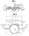
- a polishing shoe assembly is shown by Figure 1 and is designated there by reference character 10.
- Polishing shoe assembly 10 is shown with the associated support mechanisms shown schematically and is shown in position to microfinish a bearing surface of an internal combustion engine crankshaft.
- crankshaft 12 is supported at opposing ends by headstock 14 and tailstock 16 which together cause the crankshaft to be rotated about its longitudinal center axis.
- Crankshaft 12 includes a plurality of cylindrical bearing surfaces which must be microfinished including pin bearings 18 which, in use, becomes connected to a piston connecting rod; and main bearings 20, which support the crankshaft for rotation within the engine block.
- Polishing shoe assembly 10 is shown mounted to arm 22.
- Polishing shoe assembly 10 is caused to oscillate laterally along the surface being machined by oscillating the shoe assembly, or by oscillating the workpiece relative to the shoe assembly.
- Arm 22 permits polishing shoe assembly 10 to orbit with pin bearing 18 since that bearing journal is positioned eccentrically with respect to the center of rotation of crankshaft main bearings 20.
- Polishing shoe assembly 10 includes two halves, upper shoe 32 and lower shoe 34 (shown partially in phantom lines). These halves are each connected to a support structure which may include hydraulic or pneumatic biasing cylinders acting on the shoe halves (as shown in phantom lines in Figure 2) or may be supported by a scissors type linkage device.
- This polishing shoe assembly enploys a semicircular surface 24 having a plurality of spaced dovetail-shaped grooves 26. Within dovetail grooves 26 are installed cooperatively shaped urethane inserts 28. These inserts, due to the material from which they are made, are comparatively flexible and compressible, having a Durometer hardness of 90 or less.
- Each of the shoe portions include means for engaging coated abrasive tape 30 which is brought into compressive contact with the surface of pin bearing 18.
- upper and lower shoes 32 and 34 are caused to separate and are repositioned and clamped onto another pin bearing 18 or a main bearing 20.
- a plurality of polishing shoe assemblies may be provided such that the entire workpiece may be machined in one operation. Simultaneous with shoe disengagement and re-engagement is an indexing of tape 30 such that a predetermined length of new abrasive material is brought into shoe assembly 10. This indexing results in the abrasive surface being constantly renewed.
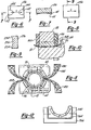
- Figure 3 illustrates a cross-sectional view taken through Figure 2 and shows contact between insert 28 and pin bearing 18.
- Insert 28 is caused to traverse relating to the surface of pin bearing 18 as indicated by arrow A.
- Insert 28, being made of a flexible material, is caused to conform to the existing surface profile of pin bearing 18. Therefore, if imperfections such as waviness, taper, convexness or concavity of the bearing surface exist, coated abrasive tape 30 will be caused to conform to the incorrect shape. As a result, this prior art microfinishing method does not correct geometry variations of the parts being microfinished.
- Figure 4 shows polishing shoe assembly 60 according to a first embodiment of this invention.
- Polishing shoe assembly 60 includes upper shoe 62 and lower shoe 64.
- Polishing shoe assembly 60 varies principally from shoe assembly 10 shown by Figures 2 and 3 in that urethane inserts 28 are replaced with stone inserts 36. These inserts are preferably made from honing stone material.
- Stones inserts 36 are characterized in that they are relatively non-deformable having a Durometer hardness greater than 90, yet are easily machined and provide a degree of frictional engagement with coated abrasive tape 30.
- Each of stone inserts 36 are mounted to a holder 38.
- Stone inserts 36 and holders 38 are preferably permitted to "float" slightly with respect to the upper and lower shoes, enabling them to rotate slightly as indicated by arrow B in Figure 5. Such relative rotation is provided according to this embodiment by mounting holders 38 using mounting pins 40.
- coated abrasive tape 30 is supported by shoes 62 and 64 such that when they engage pin bearing surface 18, the tape is brought into contact
- Stone insert 36 is provided which presents a surface having a predetermined curvature which is rigid and which exerts a compressive load on tape 30 against pin bearing 18. Since stone inserts 36 are rigid and relatively non-conformable, surface wariness, taper, convexity and concavity of the surface of pin bearing 18 are corrected since, in these instances, nonconforming portions of the surface of pin bearing 18 will be brought under greater contact pressures against coated abrasive tape 30, and therefore, more material will be removed in those areas until pin bearing 18 assumes the desired surface profile.
- Coated abrasive tape 30 is preferably of a polymeric plastic film variety which is in itself relatively incompressible.
- Abrasive coated paper products are generally unsuitable for use in connection with this invention since they are relatively compressible as compared to polymeric plastic tape materials.
- the grit size of abrasive coated papers is generally not as uniform as that of abrasive coated polymeric plastic tape materials.
- coated abrasive tape material 30 could be employed in connection with this invention.
- a metal backed tape which is coated with abrasive material could also be used.
- Figures 6 and 7 illustrate a second embodiment according to this invention.
- portions of insert 136 are partially relieved such that they do not cause high contact pressure between coated abrasive tape 30 and pin bearing 18.
- Figure 6 shows a pair of opposed relief portions 142 which are defined by arcuate borders 144.
- the surface of pin bearing 18 moves with respect to insert 136 in the direction indicated by arrow C.
- This second embodiment causes greater abrasive material removal to occur at the separated ends of the surface of pin bearing 18.
- This second embodiment therefore tends to cause the pin bearing surface to assume a slightly barrel shaped configuration, such that its diameters at each end are slightly less than the diameter at the center. Such "barrelling" is sometimes desirable to achieve optimal bearing surfaces.
- a third embodiment according to this invention is shown with reference to Figures 8 and 9.
- This embodiment also produces a slightly barrel shaped journal bearing surface but achieves this result in a different manner than that according to Figures 6 and 7.
- a modified cylindrical contour in insert 236 is produced so that the radius of the curved insert surface at points near the ends of the journal bearing is less than at the center of the journal bearing.
- relative movement of pin bearing 18 with respect to insert 236 occurs along the direction indicated by arrow C.
- portions of the surface of insert 236 near the lateral edges are designated by reference character 254 and have a radius of curvature somewhat less than that of central shoe segment 256 (these differences in radius are exaggerated in Figure 9 for illustration purposes).
- This embodiment therefore, provides another means for generating a non-cylindrical surface and a workpieoe being machined. According to this embodiment, such machining results from machining the desired surface contour directly into stone insert 236 and this contour will be impressed and machined in the corresponding workpieoe.
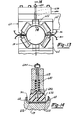
- FIG. 10 A fourth embodiment of this invention is illustrated by Figure 10, which enables the side wall portion 68 of pin bearing 18 to be finished and further permits any burrs existing between filet radius 46 and the bearing surface to be removed.
- flexible inserts 348 and 350 are provided with inserts 36. These flexible inserts exert a compressive farce against coated abrasive tape 30 when the inserts are brought to their extreme lateral positions.
- a flexible material for inserts 348 and 350 results in the same shortcomings associated with conventional processes, it is generally not necessary to highly control the profile shape of these surfaces. Since it is necessary for tape 30 to flex to a considerable extent when brought into contact with side wall portion 68, it is sometimes necessary to provide edge cuts within the coated tape, according to principles known to the prior art.
- inserts 348 and 350 further permits the elimination of burrs or sharp edges which may exist at the edges 51 of the bearing surface of journal 18 when the fillet radius are cut deep into the workpiece (as shown by Figure 10).
- inserts 348 and 350 By mounting inserts 348 and 350 such that they exert a slight compressive load on the surface of bearing 18, tape 30 is caused to remove such burrs when the insert forces the tape into the fillet.
- Figure 11 illustrates a fifth embodiment according to this invention.
- This embodiment employs inserts 36 and upper and lower shoes 62 and 64 as described in comection with Figure 4.
- This embodiment differs from the previously described embodiments in that coated abrasive tape 430 is used which has a multiplicity of perforations 452 along its length. Perforations 452 enable lubricants or cutting fluids to come in contact with the surfaces being machined. Flow of lubricant or cutting fluids to the workpiece is conducted through passage 70 within upper and lower shoes 62 and 64.
- FIG. 12 A saxth embodiment according to this invention is described with reference to Figure 12.
- lower shoe 564 is mounted within cradle 566 by a mounting pin 540.
- These mounting pins permit rotation of lower shoe assembly 564 with respect to cradle 566.
- a similar mounting arrangement would also be provided for upper shoe assembly 562 (not shown).
- This arrangement provides the desirable "floating" characteristic as described with reference to Figure 4 wherein individual mounting pins 40 are provided for each of the inserts 36.
- the construction illustrated by Figure 12 has the primary advantage of being simpler to construct. In operation, this embodiment performs as described in connection with the earlier described embodiments.
- FIG. 13 A seventh embodiment according to this invention is shown by Figures 13 and 14.
- This embodiment provides another means of finishing the side wall portions 68 of a bearing 18 or 20.
- upper shoe 62 and/or lower shoe 64 include elastcmeric insert 672 which is employed to polish the side wall portions 68.
- upper shoe 62 and lower shoe 64 are constructed identical to that described with reference to Figure 4 except that one or more of stone inserts 36 is replaced by elastomeric insert 672.
- Elastomeric insert 672 is particularly shown in detail by Figure 14.
- insert 672 is made from an elastomeric substance such as a urethane compuond and includes radiused edge surfaces 674 and 676.
- Insert 672 has a lateral width which exceeds that of stone inserts 36 such that as polishing shoe assembly 60 is stroked laterally, radiused side surfaces 674 and 676 cause coated abrasive tape 30 to contact side wall portions 68, thereby microfinishing that area.
- elastomeric insert 672 is resiliently biased within the associated shoe portion, enabling it to move radially and laterally with respect to the associated bearing surface.
- lateral compliance of elastomeric insert 672 is provided by employing drill rod 678 which flexes, enabling the insert to move laterally with respect to upper shoe 62. The maximum extent of lateral compliance is limited by contact between elastomeric insert 672 and insert holder 682.
- Radial compliance for insert 672 is provided by employing helical coil spring 680 which exerts a downward compressive force upon coated abrasive tape 30.
- the maximum extent of radial displacement is controlled by the position of head 684 on drill rod 678.
Applications Claiming Priority (2)
| Application Number | Priority Date | Filing Date | Title |
|---|---|---|---|
| US60820184A | 1984-05-07 | 1984-05-07 | |
| US608201 | 1984-05-07 |
Publications (3)
| Publication Number | Publication Date |
|---|---|
| EP0161748A2 true EP0161748A2 (de) | 1985-11-21 |
| EP0161748A3 EP0161748A3 (en) | 1987-04-22 |
| EP0161748B1 EP0161748B1 (de) | 1990-07-04 |
Family
ID=24435498
Family Applications (1)
| Application Number | Title | Priority Date | Filing Date |
|---|---|---|---|
| EP19850301582 Expired EP0161748B1 (de) | 1984-05-07 | 1985-03-07 | Einrichtung und Verfahren zur Feinstbearbeitung von Oberflächen |
Country Status (4)
| Country | Link |
|---|---|
| EP (1) | EP0161748B1 (de) |
| JP (1) | JPS60238267A (de) |
| CA (1) | CA1265343A (de) |
| DE (1) | DE3578524D1 (de) |
Cited By (14)
| Publication number | Priority date | Publication date | Assignee | Title |
|---|---|---|---|---|
| US4734964A (en) * | 1985-10-24 | 1988-04-05 | Cooper Lasersonics, Inc. | Apparatus for refurbishing acoustic members |
| EP0552885A1 (de) * | 1992-01-21 | 1993-07-28 | Norman Roy Judge | Verfahren und Vorrichtung zur Feinstbearbeitung von Bremstrommeln |
| DE4444239A1 (de) * | 1994-12-13 | 1996-06-20 | Supfina Grieshaber Gmbh & Co | Feinstbearbeitungsmaschine |
| EP0781627A1 (de) * | 1995-12-28 | 1997-07-02 | Supfina Grieshaber GmbH & Co. | Feinstbearbeitungsmaschine |
| DE19602933A1 (de) * | 1996-01-27 | 1997-07-31 | Nagel Masch Werkzeug | Verfahren und Vorrichtung zum Finishen von Umfangsflächen an Werkstücken |
| DE19607778A1 (de) * | 1996-03-01 | 1997-09-04 | Nagel Masch Werkzeug | Vorrichtung zur Finish-Bearbeitung, insbesondere von Kurbel- oder Nockenwellen |
| EP0913232A1 (de) * | 1997-10-29 | 1999-05-06 | Supfina Grieshaber GmbH & Co. | Vorrichtung zur Bearbeitung zylindrischer Werkstücke |
| DE202010006480U1 (de) | 2010-04-30 | 2010-08-05 | Nagel Maschinen- Und Werkzeugfabrik Gmbh | Andrückeinrichtung zum Andrücken von Schneidmittel, Trägerkassette für eine solche Andrückeinrichtung sowie Vorrichtung mit einer solchen Andrückeinrichtung |
| EP1160885B1 (de) * | 2000-05-31 | 2010-08-18 | Denso Corporation | Piezoelektrisches Bauelement für eine Einspritzvorrichtung |
| EP2803445A1 (de) | 2013-05-14 | 2014-11-19 | Supfina Grieshaber GmbH & Co. KG | Vorrichtung zur bandfinishen Bearbeitung eines Werkstücks |
| DE102014208319A1 (de) | 2014-05-05 | 2015-11-05 | Supfina Grieshaber Gmbh & Co. Kg | Bandfinishvorrichtung und Verfahren zum Betriebeiner Bandfinishvorrichtung |
| DE102015006672A1 (de) | 2015-05-22 | 2016-11-24 | Neenah Gessner Gmbh | Imprägnierter Schleifmittelträger für feine Körnungen und daraus hergestellter Schleifartikel |
| DE102009060926B4 (de) | 2009-12-28 | 2019-04-25 | Niles-Simmons Industrieanlagen Gmbh | Verfahren zum Fertigbearbeiten der Lagersitze von Haupt- und Hublagern von Kurbelwellen |
| WO2019115323A1 (de) * | 2017-12-14 | 2019-06-20 | Thielenhaus Technologies Gmbh | Andrückschuh |
Families Citing this family (8)
| Publication number | Priority date | Publication date | Assignee | Title |
|---|---|---|---|---|
| JPS61178168A (ja) * | 1985-02-05 | 1986-08-09 | Honda Motor Co Ltd | 超仕上げ加工用の逃げ溝加工方法 |
| JPS62236665A (ja) * | 1986-04-08 | 1987-10-16 | Fuji Heavy Ind Ltd | ワ−クの研磨布紙式自動研削装置 |
| US5095663A (en) * | 1989-02-07 | 1992-03-17 | Industrial Metal Products Corporation | Size control shoe for microfinishing machine |
| US5142827A (en) * | 1990-10-05 | 1992-09-01 | J. D. Phillips Corporation | Crankpin grinder and method |
| JP3012789B2 (ja) * | 1995-08-09 | 2000-02-28 | 株式会社京三製作所 | ラッピング装置 |
| DE19714677C5 (de) | 1997-04-09 | 2010-12-02 | Boehringer Werkzeugmaschinen Gmbh | Verfahren zur verwendungsfähigen Fertigbearbeitung von Rotationsteilen, insbesondere der Lagerstellen von Kurbelwellen |
| JP2007260811A (ja) * | 2006-03-28 | 2007-10-11 | Nachi Fujikoshi Corp | テープラップ装置 |
| JP5344941B2 (ja) * | 2009-01-30 | 2013-11-20 | ダイハツ工業株式会社 | クランクシャフトの製造方法 |
Citations (7)
| Publication number | Priority date | Publication date | Assignee | Title |
|---|---|---|---|---|
| US1905821A (en) * | 1929-03-15 | 1933-04-25 | Norton Co | Lapping device for cylindrical objects |
| US1993543A (en) * | 1932-04-29 | 1935-03-05 | Norton Co | Machine for honing and polishing crank shafts |
| US2166009A (en) * | 1938-07-20 | 1939-07-11 | Norton Co | Crankshaft lapping machine |
| US2270522A (en) * | 1940-01-27 | 1942-01-20 | Gen Motors Corp | Crankshaft bearing polishing machine |
| US2502381A (en) * | 1949-06-16 | 1950-03-28 | Norton Co | Lapping arm |
| DE881915C (de) * | 1944-03-04 | 1953-07-06 | Messerschmitt Boelkow Blohm | Steinhalter fuer Feinzieh-Schleifarbeiten |
| SU616117A1 (ru) * | 1976-04-19 | 1978-07-25 | Ордена Трудового Красного Знамени Научно-Исследовательский Институт Технологии Автомобильной Промышленности | Головка дл одновременной финишной обработки шейки и галтелей |
Family Cites Families (3)
| Publication number | Priority date | Publication date | Assignee | Title |
|---|---|---|---|---|
| US1908048A (en) * | 1930-09-02 | 1933-05-09 | Norton Co | Lapping machine |
| JPS5613584A (en) * | 1979-07-11 | 1981-02-09 | Hitachi Ltd | Setting circuit for data line potential |
| JPS58102666A (ja) * | 1981-12-10 | 1983-06-18 | Takegawa Tekko Kk | 曲面研摩用のベルトサンダ−機 |
-
1985
- 1985-02-27 CA CA000475233A patent/CA1265343A/en not_active Expired - Fee Related
- 1985-03-07 EP EP19850301582 patent/EP0161748B1/de not_active Expired
- 1985-03-07 DE DE8585301582T patent/DE3578524D1/de not_active Revoked
- 1985-03-14 JP JP5156585A patent/JPS60238267A/ja active Granted
Patent Citations (7)
| Publication number | Priority date | Publication date | Assignee | Title |
|---|---|---|---|---|
| US1905821A (en) * | 1929-03-15 | 1933-04-25 | Norton Co | Lapping device for cylindrical objects |
| US1993543A (en) * | 1932-04-29 | 1935-03-05 | Norton Co | Machine for honing and polishing crank shafts |
| US2166009A (en) * | 1938-07-20 | 1939-07-11 | Norton Co | Crankshaft lapping machine |
| US2270522A (en) * | 1940-01-27 | 1942-01-20 | Gen Motors Corp | Crankshaft bearing polishing machine |
| DE881915C (de) * | 1944-03-04 | 1953-07-06 | Messerschmitt Boelkow Blohm | Steinhalter fuer Feinzieh-Schleifarbeiten |
| US2502381A (en) * | 1949-06-16 | 1950-03-28 | Norton Co | Lapping arm |
| SU616117A1 (ru) * | 1976-04-19 | 1978-07-25 | Ордена Трудового Красного Знамени Научно-Исследовательский Институт Технологии Автомобильной Промышленности | Головка дл одновременной финишной обработки шейки и галтелей |
Non-Patent Citations (2)
| Title |
|---|
| FACHBERICHTE F]R OBERFL[CHENTECHNIK, vol. 8, no. 9/10, 1970, pages 203-208; G. HAASIS "Bandfinishen - ein wirtschaftliches Feinbearbeitungsverfahren" * |
| SOVIET INVENTIONS ILLUSTRATED, Section Mechanical, Week B21, 4th July 1979, abstract no. E6645 P61, Derwent Publications Ltd., London, GB; & SU - A - 616 117 (CAR PROD TECHN INST) 10-07-1978 * |
Cited By (23)
| Publication number | Priority date | Publication date | Assignee | Title |
|---|---|---|---|---|
| US4734964A (en) * | 1985-10-24 | 1988-04-05 | Cooper Lasersonics, Inc. | Apparatus for refurbishing acoustic members |
| EP0552885A1 (de) * | 1992-01-21 | 1993-07-28 | Norman Roy Judge | Verfahren und Vorrichtung zur Feinstbearbeitung von Bremstrommeln |
| DE4444239A1 (de) * | 1994-12-13 | 1996-06-20 | Supfina Grieshaber Gmbh & Co | Feinstbearbeitungsmaschine |
| DE4444239C3 (de) * | 1994-12-13 | 2003-05-08 | Supfina Grieshaber Gmbh & Co | Feinstbearbeitungsmaschine |
| EP0781627A1 (de) * | 1995-12-28 | 1997-07-02 | Supfina Grieshaber GmbH & Co. | Feinstbearbeitungsmaschine |
| DE19602933A1 (de) * | 1996-01-27 | 1997-07-31 | Nagel Masch Werkzeug | Verfahren und Vorrichtung zum Finishen von Umfangsflächen an Werkstücken |
| DE19602933C2 (de) * | 1996-01-27 | 1998-08-27 | Nagel Masch Werkzeug | Verfahren und Vorrichtung zum Finishen von Umfangsflächen an Werkstücken |
| DE19607778A1 (de) * | 1996-03-01 | 1997-09-04 | Nagel Masch Werkzeug | Vorrichtung zur Finish-Bearbeitung, insbesondere von Kurbel- oder Nockenwellen |
| DE19607778C2 (de) * | 1996-03-01 | 2001-10-11 | Nagel Masch Werkzeug | Vorrichtung zur Finish-Bearbeitung, insbesondere von Kurbel- oder Nockenwellen |
| EP0913232A1 (de) * | 1997-10-29 | 1999-05-06 | Supfina Grieshaber GmbH & Co. | Vorrichtung zur Bearbeitung zylindrischer Werkstücke |
| EP1160885B1 (de) * | 2000-05-31 | 2010-08-18 | Denso Corporation | Piezoelektrisches Bauelement für eine Einspritzvorrichtung |
| DE102009060926B4 (de) | 2009-12-28 | 2019-04-25 | Niles-Simmons Industrieanlagen Gmbh | Verfahren zum Fertigbearbeiten der Lagersitze von Haupt- und Hublagern von Kurbelwellen |
| DE202010006480U1 (de) | 2010-04-30 | 2010-08-05 | Nagel Maschinen- Und Werkzeugfabrik Gmbh | Andrückeinrichtung zum Andrücken von Schneidmittel, Trägerkassette für eine solche Andrückeinrichtung sowie Vorrichtung mit einer solchen Andrückeinrichtung |
| WO2014183914A1 (de) | 2013-05-14 | 2014-11-20 | Supfina Grieshaber Gmbh & Co. Kg | Vorrichtung zur bandfinishenden bearbeitung eines werkstücks |
| US10058971B2 (en) | 2013-05-14 | 2018-08-28 | Supfina Grieshaber Gmbh & Co. Kg | Device for band finishing a workpiece |
| EP2803445A1 (de) | 2013-05-14 | 2014-11-19 | Supfina Grieshaber GmbH & Co. KG | Vorrichtung zur bandfinishen Bearbeitung eines Werkstücks |
| DE102014208319A1 (de) | 2014-05-05 | 2015-11-05 | Supfina Grieshaber Gmbh & Co. Kg | Bandfinishvorrichtung und Verfahren zum Betriebeiner Bandfinishvorrichtung |
| WO2015169484A1 (de) | 2014-05-05 | 2015-11-12 | Supfina Grieshaber Gmbh & Co. Kg | Bandfinishvorrichtung und verfahren zum betrieb einer bandfinishvorrichtung |
| US9802291B2 (en) | 2014-05-05 | 2017-10-31 | Supfina Grieshaber Gmbh & Co. Kg | Belt-finishing device and method for operating a belt-finishing device |
| DE102014208319B4 (de) * | 2014-05-05 | 2021-05-06 | Supfina Grieshaber Gmbh & Co. Kg | Bandfinishvorrichtung und Verfahren zum Betrieb einer Bandfinishvorrichtung |
| DE102015006672A1 (de) | 2015-05-22 | 2016-11-24 | Neenah Gessner Gmbh | Imprägnierter Schleifmittelträger für feine Körnungen und daraus hergestellter Schleifartikel |
| DE102015006672B4 (de) * | 2015-05-22 | 2018-11-15 | Neenah Gessner Gmbh | Imprägnierter Schleifmittelträger für feine Körnungen und daraus hergestellter Schleifartikel |
| WO2019115323A1 (de) * | 2017-12-14 | 2019-06-20 | Thielenhaus Technologies Gmbh | Andrückschuh |
Also Published As
| Publication number | Publication date |
|---|---|
| EP0161748A3 (en) | 1987-04-22 |
| JPS60238267A (ja) | 1985-11-27 |
| EP0161748B1 (de) | 1990-07-04 |
| JPH0545380B2 (de) | 1993-07-09 |
| DE3578524D1 (de) | 1990-08-09 |
| CA1265343A (en) | 1990-02-06 |
Similar Documents
| Publication | Publication Date | Title |
|---|---|---|
| US4682444A (en) | Microfinishing apparatus and method | |
| EP0161748B1 (de) | Einrichtung und Verfahren zur Feinstbearbeitung von Oberflächen | |
| US5664991A (en) | Microfinishing and roller burnishing machine | |
| US4993191A (en) | Roller cam microfinishing tooling | |
| US7862404B2 (en) | Micro-concave portion machining method | |
| US5531631A (en) | Microfinishing tool with axially variable machining effect | |
| RU2162397C2 (ru) | Способ изготовления гильзы цилиндра для поршневого двигателя и узел гильзы и поршня цилиндра | |
| US20090170411A1 (en) | Micropolishing assembly for micropolishing piston rings | |
| US5803796A (en) | Microfinishing machine | |
| US5695391A (en) | Super finishing machine | |
| EP1892058B1 (de) | Schleifstein zum superfinishing und diesen verwendendes superfinishing-verfahren | |
| EP0802017B1 (de) | Vorrichtung für die Feinschleifbearbeitung von Wellen, insbesondere Kurbelwellen | |
| US4044508A (en) | Adjustable honing template | |
| EP3411181B1 (de) | Vorrichtung und verfahren zur mikrofeinbearbeitung eines schmalen sohlenzapfens | |
| GB2310626A (en) | Device for the finishing of workpieces | |
| JP3613009B2 (ja) | ホーニングヘッド | |
| US4592173A (en) | Hone for gerotor stators, and honing method | |
| Morimoto | Examination of the burnishing process using a newly-designed tool | |
| Lynah | Lapping | |
| US2932133A (en) | Work forming apparatus and method | |
| RU2120368C1 (ru) | Способ комбинированной квазипрерывистой чистовой обработки | |
| RU2275289C1 (ru) | Способ поверхностного пластического деформирования охватывающими кольцами | |
| RU2275290C1 (ru) | Охватывающее кольцо для упрочняющей обкатки | |
| RU2215636C1 (ru) | Способ абразивной обработки отверстий упругим прерывистым инструментом | |
| SU1235703A1 (ru) | Хонинговальна головка |
Legal Events
| Date | Code | Title | Description |
|---|---|---|---|
| PUAI | Public reference made under article 153(3) epc to a published international application that has entered the european phase |
Free format text: ORIGINAL CODE: 0009012 |
|
| AK | Designated contracting states |
Designated state(s): DE FR GB IT SE |
|
| PUAL | Search report despatched |
Free format text: ORIGINAL CODE: 0009013 |
|
| AK | Designated contracting states |
Kind code of ref document: A3 Designated state(s): DE FR GB IT SE |
|
| 17P | Request for examination filed |
Effective date: 19870616 |
|
| 17Q | First examination report despatched |
Effective date: 19880805 |
|
| GRAA | (expected) grant |
Free format text: ORIGINAL CODE: 0009210 |
|
| AK | Designated contracting states |
Kind code of ref document: B1 Designated state(s): DE FR GB IT SE |
|
| REF | Corresponds to: |
Ref document number: 3578524 Country of ref document: DE Date of ref document: 19900809 |
|
| ITF | It: translation for a ep patent filed |
Owner name: PROPRIA PROTEZIONE PROPR. IND. |
|
| ET | Fr: translation filed | ||
| PLBI | Opposition filed |
Free format text: ORIGINAL CODE: 0009260 |
|
| 26 | Opposition filed |
Opponent name: MASCHINENBAU GRIESHABER GMBH & CO., Effective date: 19910403 |
|
| PLAB | Opposition data, opponent's data or that of the opponent's representative modified |
Free format text: ORIGINAL CODE: 0009299OPPO |
|
| R26 | Opposition filed (corrected) |
Opponent name: MASCHINENBAU GRIESHABER GMBH & CO., Effective date: 19910403 |
|
| ITTA | It: last paid annual fee | ||
| EAL | Se: european patent in force in sweden |
Ref document number: 85301582.4 |
|
| PGFP | Annual fee paid to national office [announced via postgrant information from national office to epo] |
Ref country code: SE Payment date: 19950213 Year of fee payment: 11 |
|
| PG25 | Lapsed in a contracting state [announced via postgrant information from national office to epo] |
Ref country code: SE Effective date: 19960308 |
|
| APAC | Appeal dossier modified |
Free format text: ORIGINAL CODE: EPIDOS NOAPO |
|
| APAC | Appeal dossier modified |
Free format text: ORIGINAL CODE: EPIDOS NOAPO |
|
| EUG | Se: european patent has lapsed |
Ref document number: 85301582.4 |
|
| PGFP | Annual fee paid to national office [announced via postgrant information from national office to epo] |
Ref country code: FR Payment date: 19980221 Year of fee payment: 14 |
|
| PGFP | Annual fee paid to national office [announced via postgrant information from national office to epo] |
Ref country code: DE Payment date: 19980223 Year of fee payment: 14 |
|
| PGFP | Annual fee paid to national office [announced via postgrant information from national office to epo] |
Ref country code: GB Payment date: 19980226 Year of fee payment: 14 |
|
| PLBQ | Unpublished change to opponent data |
Free format text: ORIGINAL CODE: EPIDOS OPPO |
|
| PLAB | Opposition data, opponent's data or that of the opponent's representative modified |
Free format text: ORIGINAL CODE: 0009299OPPO |
|
| PLBQ | Unpublished change to opponent data |
Free format text: ORIGINAL CODE: EPIDOS OPPO |
|
| PLAB | Opposition data, opponent's data or that of the opponent's representative modified |
Free format text: ORIGINAL CODE: 0009299OPPO |
|
| R26 | Opposition filed (corrected) |
Opponent name: MASCHINENBAU GRIESHABER GMBH & CO., Effective date: 19910403 |
|
| R26 | Opposition filed (corrected) |
Opponent name: MASCHINENBAU GRIESHABER GMBH & CO., Effective date: 19910403 |
|
| PLAB | Opposition data, opponent's data or that of the opponent's representative modified |
Free format text: ORIGINAL CODE: 0009299OPPO |
|
| R26 | Opposition filed (corrected) |
Opponent name: SUPFINA GRIESHABER GMBH & CO. Effective date: 19910403 |
|
| APAC | Appeal dossier modified |
Free format text: ORIGINAL CODE: EPIDOS NOAPO |
|
| RDAH | Patent revoked |
Free format text: ORIGINAL CODE: EPIDOS REVO |
|
| RDAG | Patent revoked |
Free format text: ORIGINAL CODE: 0009271 |
|
| STAA | Information on the status of an ep patent application or granted ep patent |
Free format text: STATUS: PATENT REVOKED |
|
| 27W | Patent revoked |
Effective date: 19981124 |
|
| GBPR | Gb: patent revoked under art. 102 of the ep convention designating the uk as contracting state |
Free format text: 981124 |
|
| APAH | Appeal reference modified |
Free format text: ORIGINAL CODE: EPIDOSCREFNO |