EP0161142B1 - Dispositif pour alimenter un poste d'opération avec une succession d'articles guidés - Google Patents
Dispositif pour alimenter un poste d'opération avec une succession d'articles guidés Download PDFInfo
- Publication number
- EP0161142B1 EP0161142B1 EP85400608A EP85400608A EP0161142B1 EP 0161142 B1 EP0161142 B1 EP 0161142B1 EP 85400608 A EP85400608 A EP 85400608A EP 85400608 A EP85400608 A EP 85400608A EP 0161142 B1 EP0161142 B1 EP 0161142B1
- Authority
- EP
- European Patent Office
- Prior art keywords
- article
- station
- articles
- operation station
- feeding
- Prior art date
- Legal status (The legal status is an assumption and is not a legal conclusion. Google has not performed a legal analysis and makes no representation as to the accuracy of the status listed.)
- Expired
Links
- 238000005303 weighing Methods 0.000 claims description 4
- 238000007599 discharging Methods 0.000 claims 2
- 230000005693 optoelectronics Effects 0.000 claims 1
- 235000019504 cigarettes Nutrition 0.000 description 4
- 238000005259 measurement Methods 0.000 description 4
- 230000035939 shock Effects 0.000 description 3
- 241000208125 Nicotiana Species 0.000 description 2
- 235000002637 Nicotiana tabacum Nutrition 0.000 description 2
- 238000010586 diagram Methods 0.000 description 2
- 230000001133 acceleration Effects 0.000 description 1
- 235000019506 cigar Nutrition 0.000 description 1
- 238000001514 detection method Methods 0.000 description 1
- 230000005484 gravity Effects 0.000 description 1
- 238000004519 manufacturing process Methods 0.000 description 1
- 230000000391 smoking effect Effects 0.000 description 1
Images

Classifications
-
- A—HUMAN NECESSITIES
- A24—TOBACCO; CIGARS; CIGARETTES; SIMULATED SMOKING DEVICES; SMOKERS' REQUISITES
- A24C—MACHINES FOR MAKING CIGARS OR CIGARETTES
- A24C5/00—Making cigarettes; Making tipping materials for, or attaching filters or mouthpieces to, cigars or cigarettes
- A24C5/32—Separating, ordering, counting or examining cigarettes; Regulating the feeding of tobacco according to rod or cigarette condition
- A24C5/34—Examining cigarettes or the rod, e.g. for regulating the feeding of tobacco; Removing defective cigarettes
-
- A—HUMAN NECESSITIES
- A24—TOBACCO; CIGARS; CIGARETTES; SIMULATED SMOKING DEVICES; SMOKERS' REQUISITES
- A24C—MACHINES FOR MAKING CIGARS OR CIGARETTES
- A24C5/00—Making cigarettes; Making tipping materials for, or attaching filters or mouthpieces to, cigars or cigarettes
- A24C5/32—Separating, ordering, counting or examining cigarettes; Regulating the feeding of tobacco according to rod or cigarette condition
- A24C5/322—Transporting cigarettes during manufacturing
Definitions
- the present invention relates to a device for supplying an operating station with a succession of articles guided along a defined trajectory, and for evacuating said articles from said operating station along a similar trajectory, comprising a station for supplying articles , an operating station and an evacuation or sorting station for the guide means arranged between the feed station and the operation station, and first means movable in translation along the guide means for pushing each article .
- This invention can be used in all industries having to quickly control a batch of small items, in particular fragile items, where an operating station allows for example to identify or measure at least one characteristic of each item , for quick sorting, for example.
- a device of the type defined above is already known, described in Swiss patent CH-A 595,783.
- the operating station is a weighing station, and each item is pushed by a pusher towards this station. 'operation, where it comes into contact with the previous article, which it in turn pushes to evacuate and take its place.
- This device has the drawback that the rate at which the articles are handled is limited. Indeed, to handle items at high speed, it is necessary to communicate a high speed to them using the pusher. However, this speed cannot be very high for two reasons.
- the first reason is that, since it is provided, in this device, that the pushed article stops on the operating station as soon as the pusher stops pushing it, if the speed communicated to the article is too important, this article will continue its momentum, without stopping at the operating station, thus risking being thrown directly towards the evacuation station.
- the second reason is that, when this article comes into contact with the previous article to evacuate it, the shock between the two articles can be harmful to them if the pusher article has too high a speed.
- the known device also has another drawback, since, in a given configuration, this device can only properly handle articles having, for example, a given length. Thus, when the length of the articles to be handled changes, the configuration of the device must be changed. This is obviously a drawback if it is desired to use the same device for measuring the characteristics of articles of the same general shape but having significant variations in their geometric characteristics. In particular, in the tobacco industry, the length of the articles can be changed significantly.
- the present invention aims to overcome the above drawbacks.
- One of the objects of the invention is therefore to provide a device of the type defined above, in which the articles can be handled at a high speed, in order to have a high rate of handling, without losing the desired precision in positioning. articles on the operating station, and with the minimum of shocks likely to damage them.
- Another object of the invention is to provide a simple and inexpensive device capable of being adapted or automatically adapting to a substantial variation in the size of the article in the direction of travel thereof on the device.
- Another object of the invention is to be able to quickly or automatically modify the positioning of the article at the measurement or identification station as a function of characteristics of the article, for example its length, or the distribution of its mass. .
- the invention relates to a device of the type defined above, characterized in that it also comprises second means movable in translation along the guide means for retaining each article until it stops. on the operating station, while it is pushed by the first means, and to evacuate from the operating station the previous article.
- the acceleration communicated to each article can be significant in order to increase the rate of supply of the operating station without the article being badly positioned and deteriorated on its arrival on the operating station.
- the first and second means are cleats fixed on two endless belts, arranged so that a cleat, after having pushed an article, retains the following article, so that each cleat alternately fulfills the function of the first and second means.
- the operating station supply rate can be further increased.
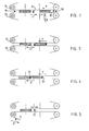
- Figure 1 is a schematic overview of the device.
- FIGS 2, 3, 4, 5 are explanatory diagrams of the flow of the transfer corresponding respectively to phases I, II, III, IV explained below.
- a hopper 1 which is intended to receive a reserve of articles to be measured, for example cigarettes, and which has an opening 2 at its lower end serving to distribute successively and one by one said articles, in a known manner.
- the device may include means 8 for detecting the length and / or the exact position of the article 7 to be transferred, for example a set of cells which in a known manner can inform the microcomputer 9 shown diagrammatically which controls the device.
- This station 4 includes as a guide means 5 a vee which extends to the operating station 6.
- This device can also be equipped with a means allowing the microcomputer to modify the position of the article at the measured.
- the mass distribution characteristics will be indicated manually by the computer equipped with a program carried out in a known manner to determine the center of gravity of the article to be weighed and to transfer it to a position at the station. of operation ensuring weighing in optimal precision conditions.
- the device further comprises two sets of means comprising at least one cleat, respectively, 10 and 11 of a shape suitable for the article to be transferred, said cleat being fixed to a belt or strip respectively 12 and 13 moving at least between the supply and discharge stations along a substantially straight path.
- this endless belt is placed in a preferably horizontal plane and driven by a stepping motor, respectively, 14 and 15 itself controlled by the microcomputer according to a law of movement programmed as a function of the cleat positions along the trajectory as explained below.
- the operating station 6 is in the example described, an electronic balance whose crew platform, mobile, comes to tangent the trajectory of the articles.
- a detection means 18, respectively, 19 signals to the computer 9 the initial position of the lugs 10 respectively 11.
- the discharge station 16 is, here, a belt driven at a speed greater than the speed of discharge of the items from the scale.
- FIG. 2 represents the operating phase of the device.
- An article 7 is supplied by the hopper 1 (not shown) at the feed station 4.
- the computer 9 (not shown), according to the information provided by the detectors 8 and 18, controls the motor 14 so as to bring the cleat 10 in contact without pressure with the article.
- the motor 15 controls the motor 15 so as to bring the cleat 11 into contact without pressure with the article 7.
- the direction movement of the cleats 10 and 11 is symbolized respectively by the arrows F and F 'in each figure 2 to 5.
- FIG. 3 represents the phase II of movement from the supply station to the measurement station.
- the computer 9 controls the motors 14 and 15 in synchronism according to a motion law determined by the program so as to minimize the transfer time without excessive brutality for the article transported. For example, we accelerate the article during part of the race, we travel another part in level, then we decelerate to reach the measuring station at a very low speed compatible with the fragility of the article transported.
- Figure 4 shows phase III of the movement, the cleat 11 which served as a stop for the transported article becomes pusher of the previous article which it then evacuates to the next station.
- FIG. 5 represents the phase IV of measurement.
- the tabs 10 and 11 return respectively to the initial but inverted positions of phase I. During this time the article being released at the measuring station can be weighed all the more quickly as the transport is carried out without shock.
Landscapes
- Manufacturing Of Cigar And Cigarette Tobacco (AREA)
- Structure Of Belt Conveyors (AREA)
- Control Of Conveyors (AREA)
Description
- La présente invention a pour objet un dispositif pour alimenter un poste d'opération avec une succession d'articles guidés suivant une trajectoire définie, et pour évacuer lesdits articles dudit poste d'opération suivant une trajectoire semblable, comprenant un poste d'alimentation en articles, un poste d'opération et un poste d'évacuation ou de triage des moyens de guidage disposés entre le poste d'alimentation et le poste d'opération, et des premiers moyens mobiles en translation le long des moyens de guidage pour pousser chaque article.
- Cette invention est utilisable dans toutes les industries ayant à contrôler rapidement un lot d'articles de petites dimensions, en particulier d'articles fragiles, où un poste d'opération permet par exemple d'identifier ou de mesurer au moins une caractéristique de chaque article, en vue d'un tri rapide, par exemple.
- Elle présente un grand intérêt dans l'industrie de la fabrication des articles à fumer, principalement pour la mesure des caractéristiques des filtres, boudins de tabac, cigarettes, cigares.
- On connaît déjà un dispositif du type défini ci-dessus, décrit dans le brevet suisse CH-A 595 783. Dans ce dispositif, le poste d'opération est un poste de pesée, et chaque article est poussé par un poussoir vers ce poste d'opération, où il entre en contact avec l'article précédent, qu'il pousse à son tour pour l'évacuer et prendre sa place.
- Ce dispositif a pour inconvénient le fait que la cadence à laquelle les articles sont manipulés est limitée. En effet, pour manipuler à grande vitesse les articles, il faut leur communiquer une vitesse importante à l'aide du poussoir. Or cette vitesse ne peut être très grande pour deux raisons.
- La première raison est que, étant donné qu'il est prévu, dans ce dispositif, que l'article poussé s'arrête sur le poste d'opération dès que le poussoir cesse de la pousser, si la vitesse communiquée à l'article est trop importante, cet article va continuer sur sa lancée, sans s'arrêter sur le poste d'opération, risquant ainsi de se trouver projeté directement vers le poste d'évacuation. La deuxième raison est que, au moment où cet article entre en contact avec l'article précédent pour l'évacuer, le choc entre les deux articles peut leur être dommageable si l'article pousseur a une vitesse trop grande. Les problèmes précédents se posent de façon particulièrement aigue lorsque les articles manipulés sont des articles légers et fragiles comme des cigarettes.
- Le dispositif connu présente également un autre inconvénient, du fait que, dans une configuration donnée, ce dispositif ne peut manipuler convenablement que des articles ayant, par exemple, une longueur donnée. Ainsi, lorsque la longueur des articles à manipuler change, la configuration du dispositif doit être changée. Ceci est évidemment un inconvénient si l'on désire utiliser un même appareil pour mesurer les caractéristiques d'articles de même forme générale mais présentant des variations importantes de leurs caractéristiques géométriques. En particulier, dans l'industrie du tabac, la longueur des articles peut être modifiée de façon importante.
- La présente invention vise à pallier les inconvénients précédents.
- Un des buts de l'invention est donc de procurer un dispositif du type défini ci-dessus, dans lequel les articles puissent être manipulés à une grande vitesse, afin d'avoir une grande cadence de manipulation, sans perdre la précision souhaitée sur le positionnement des articles sur le poste d'opération, et avec le minimum de chocs susceptibles de les endommager.
- Un autre but de l'invention est de procurer un dispositif simple et peu onéreux, capable d'être adapté ou de s'adapter automatiquement à une variation sensible de la dimension de l'article dans le sens de défilement de celui-ci sur le dispositif.
- Un autre but de l'invention est de pouvoir modifier rapidement ou automatiquement le positionnement de l'article au poste de mesure ou d'identification en fonction de caractéristiques de l'article, par exemple de sa longueur, ou de la distribution de sa masse.
- A cet effet, l'invention a pour objet un dispositif du type défini ci-dessus, caractérisé par le fait qu'il comporte également des seconds moyens mobiles en translation le long des moyens de guidage pour retenir chaque article jusqu'à l'arrêt sur le poste d'opération, tandis qu'il est poussé par les premiers moyens, et pour évacuer du poste d'opération l'article précédent.
- Ainsi l'accélération communiquée à chaque article peut être importante afin d'augmenter la cadence d'alimentation du poste d'opération sans que l'article ne se trouve mal positionné et détérioré à son arrivée sur le poste d'opération.
- Les contacts entre chaque article et les premiers et les seconds moyens sont ainsi très réduits, et les articles fragiles ne sont pas endommagés.
- Avantageusement, les premiers et les seconds moyens sont des taquets fixés sur deux courroies sans fin, agencées pour qu'un taquet, après avoir poussé un article, retienne l'article suivant, si bien que chaque taquet remplit alternativement la fonction des premiers et seconds moyens.
- Ainsi, la cadence d'alimentation du poste d'opération peut être encore augmentée.
- On comprendra mieux l'invention à travers la description détaillée d'un mode de réalisation, plus particulièrement adapté au pesage rapide de cigarettes donné à titre d'exemple non limitatif.
- La figure 1 est une vue d'ensemble schématique du dispositif.
- Les figures 2, 3, 4, 5 sont des schémas explicatifs du déroulement du transfert correspondant respectivement aux phases I, Il, III, IV explicitées ci-après.
- Dans la figure 1, on a représenté une trémie 1 qui est destinée à recevoir une réserve d'articles à mesurer, par exemple des cigarettes, et qui présente une ouverture 2 à son extrémité inférieure servant à distribuer successivement et un à un lesdits articles, de manière connue.
- Ces articles positionnés par le fond 3 de la trémie se présentent au poste d'alimentation 4. Le dispositif peut comporter un moyen 8 de détection de la longueur et/ou de la position exacte de l'article 7 à transférer par exemple un jeu de cellules qui de manière connue peut informer le micro-ordinateur 9 représenté schématiquement qui pilote le dispositif.
- Ce poste 4 comporte comme moyen de guidage 5 un vé qui se prolonge jusqu'au poste d'opération 6. Ce dispositif peut être en outre équipé d'un moyen permettant au micro-ordinateur de modifier la position de l'article au poste de mesure. Dans l'exemple particulier, non limitatif, les caractéristiques de répartition des masses seront indiquées manuellement au calculateur équipé d'un programme réalisé de manière connue pour déterminer le centre de gravité de l'article à peser et pour le transférer dans une position au poste d'opération assurant une pesée dans des conditions optimales de précision.
- Le dispositif comporte, en outre, deux ensembles de moyens comprenant au moins un taquet, respectivement, 10 et 11 de forme appropriée à l'article à transférer, ledit taquet étant fixé à une courroie ou bande respectivement 12 et 13 se déplaçant au moins entre les postes d'alimentation et d'évacuation suivant une trajectoire sensiblement rectiligne. Suivant une réalisation préférée de l'invention, cette courroie, sans fin, est placée dans un plan de préférence horizontal et animée par un moteur pas à pas, respectivement, 14 et 15 lui-même commandé par le micro-ordinateur suivant une loi de mouvement programmée en fonction des positions du taquet le long de la trajectoire comme explicité plus loin.
- Le poste d'opération 6 est dans l'exemple décrit, une balance électronique dont le plateau de l'équipage, mobile, vient tangenter la trajectoire des articles.
- Un moyen de détection 18, respectivement, 19 signale au calculateur 9 la position initiale des taquets 10 respectivement 11.
- Le poste d'évacuation 16 est, ici, une courroie animée d'une vitesse supérieure à la vitesse d'évacuation des articles de la balance.
- Pour la simplification des schémas des figures 2, 3, 4, 5, les moteurs 14 et 15 ont été représentés dans une autre position que sur la figure 1.
- La figure 2 représente la phase de fonctionnement du dispositif. Un article 7 est alimenté par la trémie 1 (non représentée) au poste d'alimentation 4. Le calculateur 9 (non représenté), en fonction des informations fournies par les détecteurs 8 et 18, pilote le moteur 14 de façon à amener le taquet 10 en contact sans pression avec l'article. A la fin du cycle précédent ou au plus tard dans le même temps en fonction des indications fournies par les détecteurs 8 et 19, il pilote le moteur 15 de façon à amener le taquet 11 en contact sans pression avec l'article 7. Le sens de mouvement des taquets 10 et 11 est symbolisé respectivement par les flèches F et F' sur chaque figure 2 à 5.
- La figure 3 représente la phase Il de mouvement depuis le poste d'alimentation jusqu'au poste de mesure.
- Pendant cette phase, le calculateur 9 pilote les moteurs 14 et 15 en synchronisme suivant une loi de mouvement déterminée par le programme de façon à diminuer au maximum le temps de transfert sans brutalité excessive pour l'article transporté. Par exemple, on accélère l'article pendant une partie de la course, on parcourt une autre partie en palier, puis on décélère pour arriver au poste de mesure à une vitesse très faible compatible avec la fragilité de l'article transporté.
- La figure 4 représente la phase III du mouvement, le taquet 11 qui servait de butée à l'article transporté devient pousseur de l'article précédent qu'il évacue alors vers le poste suivant.
- La figure 5 représente la phase IV de mesure. Les taquets 10 et 11 reprennent respectivement les positions initiales mais inversées de la phase I. Pendant ce temps l'article étant libéré au poste de mesure peut être pesé d'autant plus rapidement que le transport s'est effectué sans choc.
- On ne sort pas du cadre de l'invention en équipant les courroies d'un nombre supérieur de taquets pour limiter les courses d'initialisation, chaque taquet devenant alors successivement un taquet actif (pousseur ou butée).
- On ne sort pas du cadre de l'invention en intégrant ce dispositif à un dispositif de triage d'articles en fonction des caractéristiques mesurées au poste d'opération 6 en l'occurence un poste de mesure, remplaçcant le poste d'évacutation 16 par un poste de tri.
Claims (7)
Applications Claiming Priority (2)
| Application Number | Priority Date | Filing Date | Title |
|---|---|---|---|
| FR8405273A FR2561876B1 (fr) | 1984-04-02 | 1984-04-02 | Dispositif d'alimentation d'un poste d'operation comme l'identification ou la mesure d'au moins une caracteristique d'une succession d'articles semblables |
| FR8405273 | 1984-04-02 |
Publications (2)
| Publication Number | Publication Date |
|---|---|
| EP0161142A1 EP0161142A1 (fr) | 1985-11-13 |
| EP0161142B1 true EP0161142B1 (fr) | 1988-11-17 |
Family
ID=9302811
Family Applications (1)
| Application Number | Title | Priority Date | Filing Date |
|---|---|---|---|
| EP85400608A Expired EP0161142B1 (fr) | 1984-04-02 | 1985-03-28 | Dispositif pour alimenter un poste d'opération avec une succession d'articles guidés |
Country Status (5)
| Country | Link |
|---|---|
| US (1) | US4708237A (fr) |
| EP (1) | EP0161142B1 (fr) |
| JP (1) | JPS60244278A (fr) |
| DE (1) | DE3566215D1 (fr) |
| FR (1) | FR2561876B1 (fr) |
Families Citing this family (12)
| Publication number | Priority date | Publication date | Assignee | Title |
|---|---|---|---|---|
| DE19604928A1 (de) * | 1996-02-10 | 1997-08-14 | Natec Reich Summer Gmbh Co Kg | Rotationsscheibenstapler |
| US5929387A (en) * | 1997-06-16 | 1999-07-27 | Hi-Speed Checkweigher Co., Inc. | Indexed worm conveyor |
| US6550605B1 (en) | 1999-11-19 | 2003-04-22 | Firme Cogites Inc. | Apparatus and method for feeding elongated elements |
| DE10048007A1 (de) | 2000-09-26 | 2002-04-11 | Iwk Verpackungstechnik Gmbh | Verfahren und Vorrichtung zur Übergabe eines Produktes in einer Verpackungsmaschine |
| US7882843B2 (en) * | 2006-09-26 | 2011-02-08 | Philip Morris Usa Inc. | Smoking article component transfer device and method |
| DE102006049801A1 (de) * | 2006-10-23 | 2008-04-24 | Iwk Verpackungstechnik Gmbh | Verfahren zur Steuerung der Übergabe eines Produktstapels in einer Verpackungsmaschine |
| EP2192067B1 (fr) * | 2008-11-28 | 2013-09-18 | Müller Martini Holding AG | Dispositif d'empilement pour produits d'impression |
| IT1394525B1 (it) * | 2009-03-05 | 2012-07-05 | Eurosicma S P A | Impianto per l'alimentazione di gruppi di prodotti ad una confezionatrice |
| US20150203303A1 (en) | 2014-01-21 | 2015-07-23 | Howard Eisenberg | Device for reliably moving article from conveyor surface |
| WO2014113774A1 (fr) * | 2013-01-18 | 2014-07-24 | United Sortation Solutions, Inc. | Dispositif pour déplacer de façon fiable un article à partir d'une surface de transporteur |
| EP3009359B1 (fr) * | 2014-10-13 | 2017-07-05 | Tetra Laval Holdings & Finance S.A. | Unité d'alimentation pour alimenter des emballages scellés de produits alimentaires versables |
| US12302952B2 (en) | 2019-01-21 | 2025-05-20 | G.D Societa' Per Azioni | Machine and method for the production of a cartridge for an electronic cigarette |
Family Cites Families (15)
| Publication number | Priority date | Publication date | Assignee | Title |
|---|---|---|---|---|
| DE556988C (de) * | 1930-07-12 | 1932-08-17 | United Cigarette Mach Co Inc | Einrichtung zum periodischen Zufuehren hintereinander hergestellter Zigaretten zu einer Waage |
| US2834388A (en) * | 1954-10-04 | 1958-05-13 | Us Slicing Machine Co Inc | Slicing machine slicer, stacker, and weigher |
| FR1352304A (fr) * | 1962-02-09 | 1964-05-25 | A M F Sasib S P A | Procédé et dispositif pour espacer pneumatiquement des cigarettes ou des filtres de cigarettes en ligne continue et pour les ranger côte à côte |
| FR1532304A (fr) * | 1967-01-24 | 1968-07-12 | Dispositif de surveillance pédagogique, de contrôle de copies ou devoirs écrits et d'enregistrement des résultats | |
| GB1471534A (en) * | 1973-07-17 | 1977-04-27 | Molins Ltd | Method and apparatus for feeding rod-like articles |
| US3938650A (en) * | 1975-02-27 | 1976-02-17 | Franklin Electric Subsidiaries, Inc. | Indexing article separating and feeding conveyor |
| DE2550323C3 (de) * | 1975-11-08 | 1981-06-04 | Ipsen Industries International Gmbh, 4190 Kleve | Ladegerät zum Behältertransport |
| CH595783A5 (en) * | 1976-05-03 | 1978-02-28 | Burrus & Cie | Cigarette testing machine using electronic balance |
| US4073375A (en) * | 1977-02-09 | 1978-02-14 | Hayssen Manufacturing Company | Method of and apparatus for feeding randomly received items |
| US4240540A (en) * | 1977-12-27 | 1980-12-23 | Harris Corporation | Gating method and apparatus |
| FR2430731A1 (fr) * | 1978-07-13 | 1980-02-08 | Seita | Dispositif pour mesurer des caracteristiques physiques d'objets cylindriques tels que des cigarettes |
| JPS6013382B2 (ja) * | 1978-10-12 | 1985-04-06 | 日立化成工業株式会社 | 回転電機用カ−ボンブラシの製造法 |
| CH638663A5 (fr) * | 1980-11-11 | 1983-10-14 | Baumgartner Papiers Sa | Installation de controle d'echantillons de filtres a cigarettes. |
| US4508210A (en) * | 1982-02-13 | 1985-04-02 | E.C.H. Will (Gmbh & Co.) | Apparatus for transporting paper stacks or the like |
| US4538694A (en) * | 1983-12-01 | 1985-09-03 | Campbell Soup Company | Contacting means for guiding containers across weight platform |
-
1984
- 1984-04-02 FR FR8405273A patent/FR2561876B1/fr not_active Expired
-
1985
- 1985-03-28 DE DE8585400608T patent/DE3566215D1/de not_active Expired
- 1985-03-28 EP EP85400608A patent/EP0161142B1/fr not_active Expired
- 1985-03-29 US US06/717,453 patent/US4708237A/en not_active Expired - Lifetime
- 1985-04-02 JP JP60068616A patent/JPS60244278A/ja active Granted
Also Published As
| Publication number | Publication date |
|---|---|
| JPH0567536B2 (fr) | 1993-09-27 |
| US4708237A (en) | 1987-11-24 |
| DE3566215D1 (en) | 1988-12-22 |
| FR2561876A1 (fr) | 1985-10-04 |
| FR2561876B1 (fr) | 1986-07-18 |
| EP0161142A1 (fr) | 1985-11-13 |
| JPS60244278A (ja) | 1985-12-04 |
Similar Documents
| Publication | Publication Date | Title |
|---|---|---|
| EP0161142A1 (fr) | Dispositif pour alimenter un poste d'opération avec une succession d'articles guidés | |
| EP0283388B1 (fr) | Ensemble de calibrage de produits, tels que des fruits | |
| EP0091856A1 (fr) | Procede de regulation du transfert de produits solides identiques entre des machines amont et aval de vitesses différentes | |
| FR2522141A1 (fr) | Procede pour repartir un certain nombre de corps de poids differents en unites de poids predetermine et dispositif servant a mettre en oeuvre le procede | |
| FR2485733A1 (fr) | Dispositif automatique de fabrication d'echantillons destines a l'analyse | |
| FR2642039A1 (fr) | Procede et dispositif d'alimentation en continu de flans | |
| EP0675458B1 (fr) | Procédé automatique d'étiquetage et de contrÔle de poches de sang en retour d'analyse et machine en comportant application | |
| EP0437501A1 (fr) | Machine de tri automatique d'objets. | |
| EP0993877B1 (fr) | Station d'examen visuel de fruits | |
| EP1322534A1 (fr) | Procede et dispositif pour reguler l'espacement et la vitesse d'objets cheminant de facon aleatoire | |
| FR2730711A1 (fr) | Dispositif d'alimentation d'une unite de tri de produits longiformes, tels que carottes, unite de tri comportant ce dernier, et dispositif de distribution et calibreuse de cette unite de tri. | |
| EP0027394B1 (fr) | Procédé et dispositif de régulation, notamment pour un poste de chargement d'un système de tri automatique | |
| EP2628551A1 (fr) | Dispositif de tri de produits, notamment de fruits ou de légumes | |
| EP0011001A1 (fr) | Installation de stockage de produits en vrac sur un parc d'homogénéisation circulaire | |
| EP0696237A1 (fr) | Dispositif pour le triage d'une serie d'objets en fonction d'au moins une de leurs caracteristiques dimensionnelles et/ou ponderales | |
| EP0360687A1 (fr) | Système de remplissage automatique de boîtes en produits allongés, tels qu'haricots verts | |
| US4592434A (en) | Machines for weighing and selecting market garden produce and the like | |
| FR2749196A1 (fr) | Dispositif de convoyage de produits, notamment de fruits ou legumes, adapte pour effectuer un triage de produits en fonction de leur poids | |
| FR2476509A1 (fr) | Appareil de triage d'objets comportant au moins deux transporteurs separes par un intervalle de largeur donnee, dont l'un a une section transversale en forme de v | |
| BE1005069A6 (fr) | Dispositif automatique de separation d'enveloppes a la sortie de machines les fabriquant. | |
| FR2537903A1 (fr) | Dispositif de presentation de pieces a usiner | |
| FR2477042A1 (fr) | Installation pour le tri automatique de fruits ou analogues suivant leur calibre et leur couleur | |
| WO2024078779A1 (fr) | Installation de tri de colis équipée d'un convoyeur d'alimentation multifonctions | |
| WO2024213541A1 (fr) | Dispositif de convoyage et de séparation d'objets | |
| FR2850043A1 (fr) | Dispositif de calibrage de coquillages, notamment d'huitres |
Legal Events
| Date | Code | Title | Description |
|---|---|---|---|
| PUAI | Public reference made under article 153(3) epc to a published international application that has entered the european phase |
Free format text: ORIGINAL CODE: 0009012 |
|
| AK | Designated contracting states |
Designated state(s): DE FR GB |
|
| 17P | Request for examination filed |
Effective date: 19860127 |
|
| 17Q | First examination report despatched |
Effective date: 19870330 |
|
| GRAA | (expected) grant |
Free format text: ORIGINAL CODE: 0009210 |
|
| AK | Designated contracting states |
Kind code of ref document: B1 Designated state(s): DE FR GB |
|
| REF | Corresponds to: |
Ref document number: 3566215 Country of ref document: DE Date of ref document: 19881222 |
|
| GBT | Gb: translation of ep patent filed (gb section 77(6)(a)/1977) | ||
| PLBE | No opposition filed within time limit |
Free format text: ORIGINAL CODE: 0009261 |
|
| STAA | Information on the status of an ep patent application or granted ep patent |
Free format text: STATUS: NO OPPOSITION FILED WITHIN TIME LIMIT |
|
| 26N | No opposition filed | ||
| REG | Reference to a national code |
Ref country code: GB Ref legal event code: IF02 |
|
| PGFP | Annual fee paid to national office [announced via postgrant information from national office to epo] |
Ref country code: GB Payment date: 20030319 Year of fee payment: 19 |
|
| PGFP | Annual fee paid to national office [announced via postgrant information from national office to epo] |
Ref country code: DE Payment date: 20030326 Year of fee payment: 19 |
|
| PGFP | Annual fee paid to national office [announced via postgrant information from national office to epo] |
Ref country code: FR Payment date: 20031208 Year of fee payment: 20 |
|
| PG25 | Lapsed in a contracting state [announced via postgrant information from national office to epo] |
Ref country code: GB Free format text: LAPSE BECAUSE OF NON-PAYMENT OF DUE FEES Effective date: 20040328 |
|
| PG25 | Lapsed in a contracting state [announced via postgrant information from national office to epo] |
Ref country code: DE Free format text: LAPSE BECAUSE OF NON-PAYMENT OF DUE FEES Effective date: 20041001 |
|
| GBPC | Gb: european patent ceased through non-payment of renewal fee |
Effective date: 20040328 |