EP0161133B1 - Modulare entwickelbare Struktur für eine Scheidewand - Google Patents
Modulare entwickelbare Struktur für eine Scheidewand Download PDFInfo
- Publication number
- EP0161133B1 EP0161133B1 EP19850400540 EP85400540A EP0161133B1 EP 0161133 B1 EP0161133 B1 EP 0161133B1 EP 19850400540 EP19850400540 EP 19850400540 EP 85400540 A EP85400540 A EP 85400540A EP 0161133 B1 EP0161133 B1 EP 0161133B1
- Authority
- EP
- European Patent Office
- Prior art keywords
- panels
- wings
- structure according
- turned
- face
- Prior art date
- Legal status (The legal status is an assumption and is not a legal conclusion. Google has not performed a legal analysis and makes no representation as to the accuracy of the status listed.)
- Expired
Links
Images


Classifications
-
- E—FIXED CONSTRUCTIONS
- E04—BUILDING
- E04C—STRUCTURAL ELEMENTS; BUILDING MATERIALS
- E04C2/00—Building elements of relatively thin form for the construction of parts of buildings, e.g. sheet materials, slabs, or panels
- E04C2/02—Building elements of relatively thin form for the construction of parts of buildings, e.g. sheet materials, slabs, or panels characterised by specified materials
- E04C2/08—Building elements of relatively thin form for the construction of parts of buildings, e.g. sheet materials, slabs, or panels characterised by specified materials of metal, e.g. sheet metal
-
- E—FIXED CONSTRUCTIONS
- E04—BUILDING
- E04C—STRUCTURAL ELEMENTS; BUILDING MATERIALS
- E04C2/00—Building elements of relatively thin form for the construction of parts of buildings, e.g. sheet materials, slabs, or panels
- E04C2/30—Building elements of relatively thin form for the construction of parts of buildings, e.g. sheet materials, slabs, or panels characterised by the shape or structure
- E04C2/38—Building elements of relatively thin form for the construction of parts of buildings, e.g. sheet materials, slabs, or panels characterised by the shape or structure with attached ribs, flanges, or the like, e.g. framed panels
Definitions
- the invention relates to a scalable structure which constitutes a sealed enclosure. It applies in particular to the creation of a nuclear equipment dismantling workshop. It can also be used for storage, or in a non-hostile environment.
- the dismantling of nuclear equipment consists of dismantling or cutting pipes and equipment contaminated with radionuclides. In order to avoid spreading this contamination, these operations are carried out in a confined enclosure called an intervention workshop, built around the equipment to be dismantled.
- a confinement barrier is created during intervention operations in a contaminated environment by means of a flexible wall supported by metal masts or a metal frame consisting of an assembly of tubes or even a pneumatic frame of so as to make a sort of tent whose walls are glued and which isolates the equipment to be dismantled.
- the main drawback is that in the event of a fire, the vinyl walls are destroyed and the containment function is no longer ensured.
- the metal or pneumatic masts and frames present inside the intervention workshop form recesses which are places of retention of contamination and hinder decontamination.
- the known enclosures do not allow one or more elements to be interchanged during assembly and after decontamination of the workshop, or even during operation, to modify the initial architecture.
- the known intervention workshops do not include biological protection.
- a square or rectangular panel according to the preamble of claim 1 having a periphery shaped so as to allow the assembly of several similar panels, so as to form various structures .
- Each side of the panel has a rectangular flange perpendicular to the plane of the panel.
- the edge of the panel has holes that allow their fixing.
- Triangular or longitudinal or U-shaped connecting elements are provided.
- the border of the panel is interrupted. This panel is therefore not likely to constitute a confinement enclosure.
- the problem of sealing between the panels has not been considered.
- FR-A-2 201 375 (NURMI-NEN)
- NURMI-NEN modular panel making it possible to constitute a partition. It consists of a sheet of steel island covered with a layer of plastic material, the longitudinal edges of which are folded twice at 90 ° in order to constitute a rim with a U-shaped profile. The panels are assembled by heating the covering of material. plastic to melt it.
- the edge profile of these panels is not continuous so that they are not suitable for producing a sealed containment enclosure.
- the connection between two panels is not removable, so that they do not allow for a scalable structure.
- the object of the present invention is precisely to. remedy these drawbacks of the prior art by creating a modular modular structure of containment composed of panels.
- the panels must be removable so that a panel of a given type can be replaced by a panel of another type, or the dimensions of the structure can be varied at will by adding additional panels or by removing it.
- the structure must make it possible to constitute a perfectly sealed enclosure, in particular for the application to the creation of a containment barrier for nuclear equipment to be dismantled.
- each panel can be easily dismantled and replaced by a panel of another type.
- a seal is ensured between the panels thanks to the presence of said first wings and to the presence of a flexible plastic and non-flammable seal. Sealing remains assured even in the event of fire.
- some of said panels have a central opening, a plexiglass or metal plate being fixed to the opening by bolting on the face of the panel 4, a seal being interposed between the face and said closure plate, this plate supporting equipment such as a viewing window, glove rings, fluid passages, a remote manipulator, a container docking flange.
- the stiffening elements to which said second wings are bolted are costed by posts, beams, hexagonal plates or T-profiles to improve the rigidity of said structure.
- profiles in 1 are fixed vertically on the second wings of the folded edges and a biological protection constituted by a stack of bricks, plates or boxes, is placed parallel to the panels and between the profiles in 1.
- FIG. 1 represents a perspective view of an intervention workshop designated by the general reference 1. It consists of assembled panels which constitute both the vertical walls and the horizontal ceiling 6 of the workshop. These panels are standard panels such as panel 2 or frame panels such as panel 4 which has a central opening 4a which makes it possible to attach plexiglass or metal plates to equipment such as a viewing window, rounds of glove 5, passages necessary for connecting the ventilation 7, utility passages, the docking flange of a container, for example such as that described in document FR-A-2 418 527.
- the edges of the panels are folded twice at right angles and welded at the corners.
- the structure of the panels is reinforced by a diamond point folding 10 made with the sheet bending machine.
- the wings 8a and 8b of the U-shaped profile have fixing holes referenced respectively 9a and 9b.
- the holes 9b of the border 8b allow the panels to be fixed together so that their surfaces located inside the enclosure are at the same level. This facilitates decontamination operations during and at the end of operation, since the interior faces of the panels are as smooth as possible without grainy coating or sharp corners.
- the wings 8a of the panels have holes 11 which allow their possible fixing to an external stiffening system (see FIG. 4).
- the holes in the border 8b also allow the panels to be fixed to the floor, to the vertical walls and to the ceiling. It is made up of connecting elements and corner pieces.
- the edge of the panels also allows the installation of seals.
- the panels are rectangular or square.
- the standard panel measures 0.80 m x 1.60 m but there are also panels of 0.40 m x 1.60 m, 0.80 m x 0.80 m and 0.40 x 0.80 m.
- connection of two panels mounted perpendicularly is made by means of corner pieces ( Figures 8 and 10).
- the corner piece is bolted to each panel. It consists of a sheet folded in 1. Its length is a multiple or a submultiple of the length of a module.
- the panels can also be connected by a corner piece with four or five faces in folded and welded sheet metal ( Figures 5 to 8 and 10).
- the frame panels make it possible to adapt a large number of equipment.
- a waterproof single leaf door is mounted on an adaptable frame in place of two or more standard panels.
- the assembly is called a door panel.
- One of these doors is equipped with an anti-panic opening system, i.e. a door with a large handle and opening from the inside to the outside.
- the doors or the hatches for the equipment are single-leaf sealed. They are mounted in 1.6 x 2.4 m frames.
- the waste from the dismantling workshop is evacuated by an airlock which allows watertight docking by plating a 200-liter petroleum drum on the waste evacuation system or by placing it on a flange panel. docking described in patent FR-A-2 418 527.
- the gloves fitted to the side faces of the airlock allow the barrel to be filled, the lid to be crimped and to help position the barrel, install or remove the cover.
- the ventilation keeps the airlock in dynamic tightness.
- the maneuvering box of the cover acts as a transfer duct for the outside air to the intervention workshop to avoid contamination of the mechanics of the waste evacuation system.
- the airlock can also be equipped with a bag round of 1000 mm in diameter which allows the exit of large-scale waste under welded vinyl.
- the modular panels are sealed together using seals. These joints can be plastic joints with silicones such as Gebsicon ® or Robson O translucent.
- Said first wings 8b of the panels are assembled together in a leaktight manner by a flexible, non-flammable plastic silicone seal.
- Each of said first wings 8b is coated with each of the panels to be assembled with silicone.
- These wings are assembled by bolting. We remove the excess gasket that leaked when tightening the two panels. A certain amount of seal is added along the edge of the two panels located inside the containment, then a protective adhesive strip is placed over it. After assembly of the workshop, an adhesive strip is stuck on the corners of the modular cell. This strip facilitates the decontamination of workshops by smear or spraying with dilute nitric acid or conventional detergents.
- connection elements 9 constituted by metal belts make it possible to make up for the faults of civil engineering, that is to say floors, ceilings and walls. The installation of these elements must be done before mounting the panels. They consist of a sheet of stainless steel folded twice at right angles. One of the branches is placed on the ground. The other branch supports the panel ( Figure 4). Their length is a submultiple or a multiple of the length of a standard panel.
- the panels can, if necessary, be maintained by a frame.
- This frame is then built outside the workshop and can be adapted to its dimensions. It will be constituted for example by profiles or lattice girders.
- the connecting elements at right angles to the sectional panels shown in FIG. 5 allow the dimensions of the workshop to be extended.
- One element comprises folded U-shaped edges, the wings 18a, 18b of which are provided with fixing holes 19b, allowing them to be fixed to the panels and possibly holes 19a allowing their fixing to an external stiffening system.
- the posts or the beams are fixed on the civil engineering, like the belts, by means of dowels and bolted on the folded side of the panels. They optionally serve to fix the biological protections 20 shown in FIG. 9.
- An intervention workshop carried out using modular panels of the invention has many advantages.
- the self-supporting structure of the workshop and the modularity of all of its metal panels and accessories allow one or more elements to be exchanged with one or more others both during assembly and during operation and after decontamination of the workshop. to modify its initial architecture.
- An important advantage of the invention resides in the fact that the design of the panels with structure turned towards the exterior makes it possible to have an internal surface free of any structure capable of becoming a place of retention and discomfort for decontamination.
- the dismantling workshop is made of stainless steel to avoid corrosion of the panels, but it can be made of any other metal or material, in particular self-extinguishing composite materials.
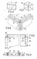
- FIG. 6 There are shown in Figures 6 and 7 two embodiments of a connecting element for connecting three walls in a scalable structure according to the invention.
- the element 40 (FIG. 6) has four walls, namely two complete square walls and two other walls constituted by squares of which a corner has been cut. Each of these faces is pierced with a hole which allows its fixing by bolting to the second wings 8a of the panels.
- the connecting element 42 (FIG. 7) consists of a cube from which one of the faces has been removed. It thus has five square walls each having a hole which allows it to be bolted to the second wings 8a of the panels.
- Figure 5 a partial view of a structure according to the invention illustrating the connection of two walls formed by perpendicular panels.
- connection elements There is a connecting element 44. It is fixed by bolting its first wings 18b to panels, 2 the representation of which has only been started in FIG. 5. The corner shown in FIG. 5 is therefore a re-entrant corner.
- the folded sides of the edge of the panels allow beams, posts or standard profiles to be fixed suitable for biological protection, namely seasoned lead bricks, borated concrete bricks, more or less thick concrete slabs, boxes filled with lead shot, etc.
- Protective means can also be used neutrophages, such as paraffin bricks or boxes filled with water, in the event of a risk of criticality excursion.
- FIG 9 There is shown in Figure 9, the means which allow the attachment of a biological protection wall to the outer wall of a structure according to the invention.
- These means consist of profiles 52 in I. Two of the wings of these profiles are used to fix them by bolting to the first wings 8b of the panels 2 forming a wall of the structure, as shown diagrammatically by the dashed lines 54.
- the wings of the profiles 52 serve as guides and for holding the biological protection wall 20.
- This wall is formed by a stack of lead bricks. It could also consist of plates or boxes. It is placed parallel to the panels 2 or 4, and disposed between the sections 52.
- Profiles such as profiles 52 could also be used to improve the rigidity of the structure without a biological protection wall being arranged parallel to the panels. Instead of the profiles, one could also use posts or beams to improve the rigidity of the structure, the latter being bolted to the second wings 8a of the panels.
- FIG. 10 shows a bottom view of the junction between three panels 2.
- the exterior and interior of the structure have been designated by the references 48 and 50 respectively.
- angles 46 are located outside the structure.
- connection element 46 There is a first type of connection element consisting of a simple angle iron 46 having two faces at right angles pierced with holes. This angle 46 is fixed by bolting to a first wing 8b of the panels 2. It is noted that the first and second wings of the panels 2, as well as the first and second wings of the connecting element 46, are located towards the outside of the enclosure. The exterior 48 of this enclosure has been designated by the reference 48 and the interior located by the reference 50. The corner shown in Figure 8 is therefore a re-entrant corner. It is therefore noted that the angle iron 46 is located inside the enclosure. Finally, there is a connection element 40, as illustrated in FIG. 6, at the junction between the connection element 44 and the panel 2 fixed to the angle iron 46. We could also have used a connection element 42 of Figure 7.
Claims (8)
Applications Claiming Priority (2)
| Application Number | Priority Date | Filing Date | Title |
|---|---|---|---|
| FR8404458 | 1984-03-22 | ||
| FR8404458A FR2561692B1 (fr) | 1984-03-22 | 1984-03-22 | Panneau modulaire et atelier de demantelement constitue par assemblage de ces panneaux |
Publications (2)
| Publication Number | Publication Date |
|---|---|
| EP0161133A1 EP0161133A1 (de) | 1985-11-13 |
| EP0161133B1 true EP0161133B1 (de) | 1988-12-07 |
Family
ID=9302341
Family Applications (1)
| Application Number | Title | Priority Date | Filing Date |
|---|---|---|---|
| EP19850400540 Expired EP0161133B1 (de) | 1984-03-22 | 1985-03-21 | Modulare entwickelbare Struktur für eine Scheidewand |
Country Status (3)
| Country | Link |
|---|---|
| EP (1) | EP0161133B1 (de) |
| DE (1) | DE3566694D1 (de) |
| FR (1) | FR2561692B1 (de) |
Families Citing this family (6)
| Publication number | Priority date | Publication date | Assignee | Title |
|---|---|---|---|---|
| FR2668789A1 (fr) * | 1990-11-05 | 1992-05-07 | Accm Sarl | Systeme de panneaux modulable permettant le confinement de travaux et l'isolement des hommes en milieux nocifs. |
| FR2724192B1 (fr) | 1994-09-07 | 1996-10-25 | Cogema | Ensemble de confinement modulaire delimitant un volume clos evolutif |
| GB2310224A (en) * | 1996-02-15 | 1997-08-20 | Shapland & Petter Ltd | Partition |
| DE19712619C1 (de) * | 1997-03-26 | 1999-01-07 | Thomas Robert Metall Elektro | Kammer- oder Tunneltrockner sowie Vorwärmer für keramische Formlinge |
| FI4046U1 (fi) * | 1998-05-15 | 1999-07-09 | Wsab Puutavarakuivaamot Oy | Rakennuselementti |
| FR2963943B1 (fr) | 2010-08-22 | 2013-05-31 | Sperian Prot Clothing | Sas de confinement |
Family Cites Families (3)
| Publication number | Priority date | Publication date | Assignee | Title |
|---|---|---|---|---|
| GB791706A (en) * | 1954-10-23 | 1958-03-12 | Gabriel Renard | Panels for use as constructional units and the structures formed therefrom |
| FR2109017B3 (de) * | 1970-10-30 | 1977-01-21 | Air Ind | |
| AT320237B (de) * | 1971-06-04 | 1975-01-27 | Anton H Dinkel | Bausystem, insbesondere zur Errichtung von Gebäuden und Fahrzeugaufbauten |
-
1984
- 1984-03-22 FR FR8404458A patent/FR2561692B1/fr not_active Expired
-
1985
- 1985-03-21 EP EP19850400540 patent/EP0161133B1/de not_active Expired
- 1985-03-21 DE DE8585400540T patent/DE3566694D1/de not_active Expired
Also Published As
| Publication number | Publication date |
|---|---|
| DE3566694D1 (en) | 1989-01-12 |
| FR2561692B1 (fr) | 1986-11-14 |
| EP0161133A1 (de) | 1985-11-13 |
| FR2561692A1 (fr) | 1985-09-27 |
Similar Documents
| Publication | Publication Date | Title |
|---|---|---|
| FR2905710A1 (fr) | Edifice et procede de montage, notamment d'habitation | |
| EP0161133B1 (de) | Modulare entwickelbare Struktur für eine Scheidewand | |
| FR2552798A1 (fr) | Structure de mur-rideau a cadres metalliques, a ruptures phonique et thermique | |
| WO1998054418A1 (fr) | Ossature de batiment | |
| FR2960578A1 (fr) | Element de construction modulaire | |
| EP3666987A1 (de) | Vakuumhülle für selbststehendes, selbstisslierendes, schwimmendes, erdbebensicheres, und halbmobiles, gebäude | |
| JP2013119712A (ja) | 水密扉 | |
| EP0701032B1 (de) | Modularer Umfassungs-Satz zum Abgrenzen eines erweiterbaren, umschlossenen Rauminhaltes | |
| WO2007118953A1 (fr) | Assemblage d'angle comportant un element male preforme selon un angle predetermine et borde par des retours | |
| EP0365512A1 (de) | Vorgefertigte Bauelemente zur Errichtung von Gebaüden und Bauverfahren zur Errichtung von Gebaüden mittels dieser Bauelemente | |
| FR3011862A1 (fr) | Module de construction | |
| CH630433A5 (en) | Element intended for producing prefabricated structures | |
| FR3088080A1 (fr) | Conteneur ou bungalow de stockage de produits dangereux | |
| EP3553244B1 (de) | Konstruktionselement und konstruktion mit einem solchen element | |
| EP0041044B1 (de) | Sechseckige Bauwerke | |
| EP3754129B1 (de) | Nicht tragende holzrahmenfassade | |
| EP0133177A2 (de) | Vorgefertigte Lichtkuppeln mit profilierten Quertraversen zur Befestigung derselben und Verglasung mit doppelter Dichtung am Umfang | |
| FR2532978A1 (fr) | Caveau funeraire en elements prefabriques et assembles | |
| FR2624192A1 (fr) | Dispositif qui permet d'assurer les fonctions de linteau et de coffre de volet roulant combinees avec ou sans precadre metallique | |
| FR2710289A1 (fr) | Panneau composite pour la construction. | |
| FR2746130A1 (fr) | Enceinte de confinement d'une installation industrielle a risques et procede de fabrication d'une telle enceinte | |
| FR2820161A1 (fr) | Procede de montage d'un abri d'urgence et abri resultant de la mise en oeuvre de ce procede | |
| FR2656021A1 (fr) | Panneaux de bardage modulaire pour structures planes ou courbes et procede de montage. | |
| WO1997031172A1 (fr) | Cloison etanche de protection de batiments | |
| FR2485603A1 (fr) | Abris pour la protection civile |
Legal Events
| Date | Code | Title | Description |
|---|---|---|---|
| PUAI | Public reference made under article 153(3) epc to a published international application that has entered the european phase |
Free format text: ORIGINAL CODE: 0009012 |
|
| AK | Designated contracting states |
Designated state(s): BE DE FR GB IT |
|
| 17P | Request for examination filed |
Effective date: 19860416 |
|
| 17Q | First examination report despatched |
Effective date: 19870514 |
|
| RAP1 | Party data changed (applicant data changed or rights of an application transferred) |
Owner name: COMMISSARIAT A L'ENERGIE ATOMIQUE |
|
| GRAA | (expected) grant |
Free format text: ORIGINAL CODE: 0009210 |
|
| AK | Designated contracting states |
Kind code of ref document: B1 Designated state(s): BE DE FR GB IT |
|
| ITF | It: translation for a ep patent filed |
Owner name: JACOBACCI & PERANI S.P.A. |
|
| REF | Corresponds to: |
Ref document number: 3566694 Country of ref document: DE Date of ref document: 19890112 |
|
| GBT | Gb: translation of ep patent filed (gb section 77(6)(a)/1977) | ||
| PLBE | No opposition filed within time limit |
Free format text: ORIGINAL CODE: 0009261 |
|
| STAA | Information on the status of an ep patent application or granted ep patent |
Free format text: STATUS: NO OPPOSITION FILED WITHIN TIME LIMIT |
|
| 26N | No opposition filed | ||
| ITTA | It: last paid annual fee | ||
| REG | Reference to a national code |
Ref country code: FR Ref legal event code: CL |
|
| REG | Reference to a national code |
Ref country code: GB Ref legal event code: IF02 |
|
| PGFP | Annual fee paid to national office [announced via postgrant information from national office to epo] |
Ref country code: GB Payment date: 20040317 Year of fee payment: 20 |
|
| PGFP | Annual fee paid to national office [announced via postgrant information from national office to epo] |
Ref country code: FR Payment date: 20040326 Year of fee payment: 20 |
|
| PGFP | Annual fee paid to national office [announced via postgrant information from national office to epo] |
Ref country code: DE Payment date: 20040402 Year of fee payment: 20 |
|
| PGFP | Annual fee paid to national office [announced via postgrant information from national office to epo] |
Ref country code: BE Payment date: 20040518 Year of fee payment: 20 |
|
| PG25 | Lapsed in a contracting state [announced via postgrant information from national office to epo] |
Ref country code: GB Free format text: LAPSE BECAUSE OF EXPIRATION OF PROTECTION Effective date: 20050320 |
|
| BE20 | Be: patent expired |
Owner name: *COMMISSARIAT A L'ENERGIE ATOMIQUE Effective date: 20050321 |
|
| REG | Reference to a national code |
Ref country code: GB Ref legal event code: PE20 |
|
| BE20 | Be: patent expired |
Owner name: *COMMISSARIAT A L'ENERGIE ATOMIQUE Effective date: 20050321 |