EP0160593B1 - Vorrichtung zur Handhabung eines Schutzrohres für einen Giessstrahl - Google Patents
Vorrichtung zur Handhabung eines Schutzrohres für einen Giessstrahl Download PDFInfo
- Publication number
- EP0160593B1 EP0160593B1 EP85400580A EP85400580A EP0160593B1 EP 0160593 B1 EP0160593 B1 EP 0160593B1 EP 85400580 A EP85400580 A EP 85400580A EP 85400580 A EP85400580 A EP 85400580A EP 0160593 B1 EP0160593 B1 EP 0160593B1
- Authority
- EP
- European Patent Office
- Prior art keywords
- carriage
- fact
- tube
- shaft
- arm
- Prior art date
- Legal status (The legal status is an assumption and is not a legal conclusion. Google has not performed a legal analysis and makes no representation as to the accuracy of the status listed.)
- Expired
Links
Images

Classifications
-
- B—PERFORMING OPERATIONS; TRANSPORTING
- B22—CASTING; POWDER METALLURGY
- B22D—CASTING OF METALS; CASTING OF OTHER SUBSTANCES BY THE SAME PROCESSES OR DEVICES
- B22D41/00—Casting melt-holding vessels, e.g. ladles, tundishes, cups or the like
- B22D41/50—Pouring-nozzles
- B22D41/56—Means for supporting, manipulating or changing a pouring-nozzle
Definitions
- the present invention relates to the handling of a protective tube for a pouring stream, with a view to placing said tube under the orifice of a container, such as a ladle containing molten metal.
- This tube is intended to immerse in the metal. fusion contained in another container, such as a pouring distributor placed under the preceding container.
- the handling device having all the characteristics of the preamble of claim 1 described in document FR-A-2,399,295 and which comprises a carriage movable along a horizontal track, a vertical barrel integral with said carriage and a carrying arm supported by said barrel and provided with means for gripping the protective tube has a limited radius of action and has only one degree of freedom in a horizontal plane.
- the main object of the invention is to solve this problem by limiting human intervention to the sole final positioning of the tube and by making it possible to automate the various operations of the handling device.
- a device for handling a tube protecting a casting jet in particular for applying said tube under the orifice of a molten metal casting ladle, or the '' removing therefrom, comprising a first carriage movable along a horizontal track, a vertical barrel integral with said carriage, an arm carrying the jet protection tube supported by said barrel and means for gripping the tube by the carrying arm, characterized in that it further comprises means for controlling the rotation of said barrel about its longitudinal axis, a second carriage movable vertically along the barrel under the action of drive means and a counterweight holding the second carriage in position when the drive means of said carriage have ceased to act, and in that the carrying arm is articulated to the second carriage by means of a connecting rod.
- the connecting rod is provided with a locking system in position, said system being rendered inoperative after application of the tube under the ladle.
- the locking system consists of two roller support arms arranged on either side of the connecting rod and controlled by jacks.
- the support arm is mounted to rotate about its longitudinal axis, the drive means of said arm being mounted at the end of the latter, opposite to that which carries the tube.
- the means for gripping the tube by the support arm consist of clamps, the means for driving said clamps being mounted at the end of the arm opposite to them.
- the means for controlling the rotation of the barrel about its longitudinal axis comprise an orientation ring connecting the barrel to the first carriage.
- the drive means of the second carriage in the vertical direction comprise a chain, one end of which is fixed to said carriage and the other to the counterweight, a return wheel of said chain and a geared motor group, the latter controlling the rotation of the idler wheel via a brake and a clutch.
- the first carriage and all of the elements which are attached to it are mounted suspended.
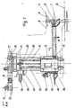
- the reference numeral 1 designates the tube for protecting a casting jet resting under a first container, such as a ladle 2.
- This tube is intended to immerse in the molten metal collected by a second container, such as a continuous casting distributor 3, placed under the casting ladle 2.
- a drawer system 4 makes it possible, on request, to authorize the flow or to interrupt it.
- the tube 1 is held by a system of clamps 5 mounted at the end of a support arm 6.
- a system of clamps 5 mounted at the end of a support arm 6.
- it is essential to provide a certain number of movements: horizontal translation of the arm carrier 6, rotation of said carrier arm about a vertical axis, vertical translation of said carrier arm and possibly rotation of said carrier arm about its longitudinal axis.
- It is also necessary to provide a means of controlling the clamp system 5 and degrees of freedom to collect the variations in position of the ladle 2, allow the opening or closing of the drawer system 4, and ensure the correct positioning of the tube 1 under the casting jet, more precisely under the nozzle 7 of the casting ladle 2.
- the carrying arm 6, by means of a support box 8 and a connecting rod 19, is made integral with a carriage 9 vertically movable along a barrel 10 capable of being driven in rotation around its axis by an orientation ring 11, which is integral with a carriage 12, horizontally movable along a suspended track 13.
- This mechanically welded construction carriage is a self-propelled carriage mounted on rollers, such as 14, rolling on the track 13.
- the movement is controlled by a geared motor group 15 mounted on one end of the carriage 12 and which rotates the rollers 14 located at the other end of said carriage by a chain transmission 16.
- the rotation of the support arm 6 around the axis of the barrel 10 is controlled by a geared motor group 17 secured to the carriage 12, by means of the slewing ring 11 interposed between the barrel 10 and the carriage 12.
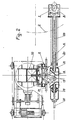
- the barrel 10 is provided with rails for guiding the vertical movement of the carriage 9 which will be discussed later.
- a connecting rod 19 fixed to the carriage 9 supports the support box assembly 8 - carrier arm 6.
- the assembly is locked, during handling, by means of two roller-carrying arms such as 20, which position the connecting rod 19 and therefore the support 8 and the support arm 6 in a predetermined position.
- the control of the arms 20 is ensured by pneumatic cylinders such as 21.
- the assembly being unlocked, during casting, two degrees of freedom are obtained for the movement of the drawer system 4, without any reaction on the other elements of the device. handling.
- the movement is controlled by a geared motor unit 25 integral with the barrel 10 by means of a brake 26 and a clutch 27.
- a geared motor unit 25 integral with the barrel 10 by means of a brake 26 and a clutch 27.
- the rotation of the carrier arm 6 about its longitudinal axis is controlled by a geared motor group 28 via a wheel 29 and a chain 30.
- the arm 6 is mounted on two rolling bearings, such as 31 , carried by the support box 8.
- the control is provided with an angular play of ⁇ 5 ° relative to the vertical position of the tube 1. This results in an additional degree of freedom.
- the invention therefore covers, in addition to the example illustrated, its various possible alternative embodiments.
Landscapes
- Engineering & Computer Science (AREA)
- Mechanical Engineering (AREA)
- Casting Support Devices, Ladles, And Melt Control Thereby (AREA)
- Moulds For Moulding Plastics Or The Like (AREA)
- Perforating, Stamping-Out Or Severing By Means Other Than Cutting (AREA)
- Lining Or Joining Of Plastics Or The Like (AREA)
- Pipe Accessories (AREA)
- Ultra Sonic Daignosis Equipment (AREA)
- Non-Disconnectible Joints And Screw-Threaded Joints (AREA)
Claims (8)
Vorrichtung nach Anspruch 1, dadurch gekennzeichnet, dass die Pleuelstange (19) mit einem Positions-verriegelungssystem versehen ist, wobei dieses system nach Ansetzen des Schutzrohres (1) unter der Giesspfanne (2) unwirksam gemacht wird.
Priority Applications (1)
| Application Number | Priority Date | Filing Date | Title |
|---|---|---|---|
| AT85400580T ATE27687T1 (de) | 1984-04-04 | 1985-03-26 | Vorrichtung zur handhabung eines schutzrohres fuer einen giessstrahl. |
Applications Claiming Priority (2)
| Application Number | Priority Date | Filing Date | Title |
|---|---|---|---|
| FR8405287 | 1984-04-04 | ||
| FR8405287A FR2562448B1 (fr) | 1984-04-04 | 1984-04-04 | Dispositif de manipulation d'un tube de protection d'un jet de coulee |
Publications (2)
| Publication Number | Publication Date |
|---|---|
| EP0160593A1 EP0160593A1 (de) | 1985-11-06 |
| EP0160593B1 true EP0160593B1 (de) | 1987-06-10 |
Family
ID=9302822
Family Applications (1)
| Application Number | Title | Priority Date | Filing Date |
|---|---|---|---|
| EP85400580A Expired EP0160593B1 (de) | 1984-04-04 | 1985-03-26 | Vorrichtung zur Handhabung eines Schutzrohres für einen Giessstrahl |
Country Status (5)
| Country | Link |
|---|---|
| US (1) | US4643339A (de) |
| EP (1) | EP0160593B1 (de) |
| AT (1) | ATE27687T1 (de) |
| DE (1) | DE3560229D1 (de) |
| FR (1) | FR2562448B1 (de) |
Families Citing this family (5)
| Publication number | Priority date | Publication date | Assignee | Title |
|---|---|---|---|---|
| AT386777B (de) * | 1986-06-03 | 1988-10-10 | Stangl Kurt Dipl Ing | Manipulator zum ansetzen eines giessrohres an den ausgussschieber einer giesspfanne |
| AT408077B (de) * | 1992-08-25 | 2001-08-27 | Ferro Montagetechnik Ges M B H | Manipulator zum ansetzen eines giessrohres an den ausgussschieber einer giesspfanne |
| AT413950B (de) * | 2004-05-26 | 2006-07-15 | Voest Alpine Ind Anlagen | Stranggiessanlage mit mindestens einem roboter und verfahren zum betrieb einer stranggiessanlage unter einbindung von mindestens einem roboter |
| CN203795558U (zh) | 2012-11-02 | 2014-08-27 | 科勒公司 | 用于具有蓄水箱的马桶的非接触式致动系统 |
| GB2537090B (en) * | 2015-01-22 | 2017-09-13 | Monocon Int Refractories Ltd | Shroud tube manipulator |
Family Cites Families (12)
| Publication number | Priority date | Publication date | Assignee | Title |
|---|---|---|---|---|
| US3033059A (en) * | 1958-09-19 | 1962-05-08 | Gen Mills Inc | Drive means for remote control manipulator |
| US3665148A (en) * | 1971-04-07 | 1972-05-23 | Gen Motors Corp | Six-axis manipulator |
| DE2800503A1 (de) * | 1977-01-27 | 1978-08-03 | Uss Eng & Consult | Vorrichtung zum anbringen eines giessrohres fuer einen giessbehaelter |
| FR2399295A1 (fr) * | 1977-08-03 | 1979-03-02 | Fives Cail Babcock | Dispositif pour la manutention, la mise en place sur une poche ou un repartiteur et le remplacement d'un tube de coulee |
| US4227851A (en) * | 1978-08-18 | 1980-10-14 | Stelron Cam Company | Device for picking up and placing articles on movable conveyors and assembly lines and to an endless conveyor construction and to an article pickup and deposit device therefor |
| US4313596A (en) * | 1979-10-29 | 1982-02-02 | Flo-Con Systems, Inc. | Shroud support and method for shroud engagement with teeming valve |
| US4381102A (en) * | 1979-10-29 | 1983-04-26 | Flo-Con Systems, Inc. | Shroud support and method for shroud engagement with teeming valve |
| US4262827A (en) * | 1979-12-26 | 1981-04-21 | Bethlehem Steel Corporation | Ladle shroud apparatus |
| FR2482508A1 (fr) * | 1980-05-14 | 1981-11-20 | Commissariat Energie Atomique | Manipulateur et support d'orientation motorise pour un tel manipulateur |
| JPS571185A (en) * | 1980-06-03 | 1982-01-06 | Mitsubishi Electric Corp | Elevator device |
| US4316561A (en) * | 1980-08-05 | 1982-02-23 | United States Steel Corporation | Pour tube latching apparatus |
| US4550867A (en) * | 1983-10-14 | 1985-11-05 | National Steel Corporation | Shroud tube manipulating and supporting apparatus |
-
1984
- 1984-04-04 FR FR8405287A patent/FR2562448B1/fr not_active Expired
-
1985
- 1985-03-22 US US06/714,819 patent/US4643339A/en not_active Expired - Fee Related
- 1985-03-26 DE DE8585400580T patent/DE3560229D1/de not_active Expired
- 1985-03-26 EP EP85400580A patent/EP0160593B1/de not_active Expired
- 1985-03-26 AT AT85400580T patent/ATE27687T1/de not_active IP Right Cessation
Also Published As
| Publication number | Publication date |
|---|---|
| FR2562448B1 (fr) | 1986-07-04 |
| DE3560229D1 (en) | 1987-07-16 |
| FR2562448A1 (fr) | 1985-10-11 |
| EP0160593A1 (de) | 1985-11-06 |
| US4643339A (en) | 1987-02-17 |
| ATE27687T1 (de) | 1987-06-15 |
Similar Documents
| Publication | Publication Date | Title |
|---|---|---|
| EP0230593B1 (de) | Automatisierte Anlage zum Ausmauern der Innenwand eines Gefässes | |
| FR2620462A1 (fr) | Dispositif d'enlevement de la matiere de tas de fibres, notamment de balles de matiere filable | |
| EP0160593B1 (de) | Vorrichtung zur Handhabung eines Schutzrohres für einen Giessstrahl | |
| EP0326461B1 (de) | Vorrichtung und Verfahren zum Schleudern einer Auskleidung auf die Innenfläche eines metallurgischen Gefässes | |
| EP1129221B1 (de) | Verteilerschurre für schüttgut | |
| BE897688A (fr) | Appareil de raclage de scories | |
| FR2695853A1 (fr) | Machine à fraiser, à surfacer et à polir à changement automatique d'outils et dispositif correspondant. | |
| EP0464427A2 (de) | Vorrichtung zum automatischen Ankuppeln einer Einblaslanze an ein Sammelgefäss | |
| EP0061227B1 (de) | Auf dem Gleis fahrbare Schotterplaniermaschine | |
| EP0079290A1 (de) | Vorrichtung zum Temperaturmessen und/oder Probenehmen bei einer Frischeinrichtung | |
| CH652774A5 (fr) | Machine de chantier ferroviaire dont le chassis roulant est equipe d'un dispositif pour lever et riper une voie ferree. | |
| FR2524511A1 (fr) | Appareil de pliage de vetements, en particulier de blouses | |
| EP0248251A1 (de) | Automatisierte Vorrichtung zum Ausmauern eines Gefässes | |
| JP3629115B2 (ja) | 取鍋移動装置 | |
| FR2685653A1 (fr) | Dispositif de refection du revetement interieur d'un trou de coulee notamment d'un convertisseur d'acierie. | |
| LU88462A1 (fr) | Dispositif pour changer des tiges de forage et/ou de perçage sur une machine de perçage d'un trou de coulée | |
| FR2673586A1 (fr) | Machine pour l'entretien d'une ligne de contact. | |
| FR2674330A1 (fr) | Dispositif de mise en position de rotors, notamment de roues de vehicules automobiles, sur des machines d'equilibrage. | |
| CA1118596A (fr) | Dispositif pour la manutention des differents elements d'une installation d'injection d'air prechauffe dans un four a cuve | |
| US4878789A (en) | Apparatus for cleaning titanium pots | |
| EP0122904A2 (de) | Schieberverschluss für Behälter in der Stahl-Eisen Industrie oder Metallurgie | |
| WO1980000136A1 (fr) | Procede et dispositif de manutention en fonderie | |
| BE1011299A6 (fr) | Appareil de manutention automatique d'un tube de coulee. | |
| EP0061969B1 (de) | Tunnelvortriebsmaschine mit einem mit Werkzeugen ausgerüsteten Drehbohrkopf und einer Vorrichtung zum Montieren der Ausbauelemente | |
| FR2565138A1 (fr) | Installation d'alimentation en fonte liquide d'une machine de coulee centrifuge |
Legal Events
| Date | Code | Title | Description |
|---|---|---|---|
| PUAI | Public reference made under article 153(3) epc to a published international application that has entered the european phase |
Free format text: ORIGINAL CODE: 0009012 |
|
| AK | Designated contracting states |
Designated state(s): AT BE DE GB NL |
|
| 17P | Request for examination filed |
Effective date: 19851202 |
|
| 17Q | First examination report despatched |
Effective date: 19860606 |
|
| GRAA | (expected) grant |
Free format text: ORIGINAL CODE: 0009210 |
|
| AK | Designated contracting states |
Kind code of ref document: B1 Designated state(s): AT BE DE GB NL |
|
| REF | Corresponds to: |
Ref document number: 27687 Country of ref document: AT Date of ref document: 19870615 Kind code of ref document: T |
|
| REF | Corresponds to: |
Ref document number: 3560229 Country of ref document: DE Date of ref document: 19870716 |
|
| PLBE | No opposition filed within time limit |
Free format text: ORIGINAL CODE: 0009261 |
|
| STAA | Information on the status of an ep patent application or granted ep patent |
Free format text: STATUS: NO OPPOSITION FILED WITHIN TIME LIMIT |
|
| 26N | No opposition filed | ||
| PG25 | Lapsed in a contracting state [announced via postgrant information from national office to epo] |
Ref country code: GB Effective date: 19890326 Ref country code: AT Effective date: 19890326 |
|
| PG25 | Lapsed in a contracting state [announced via postgrant information from national office to epo] |
Ref country code: BE Effective date: 19890331 |
|
| BERE | Be: lapsed |
Owner name: FIVES-CAIL BABCOCK S.A. Effective date: 19890331 |
|
| PG25 | Lapsed in a contracting state [announced via postgrant information from national office to epo] |
Ref country code: NL Effective date: 19891001 |
|
| NLV4 | Nl: lapsed or anulled due to non-payment of the annual fee | ||
| GBPC | Gb: european patent ceased through non-payment of renewal fee | ||
| PG25 | Lapsed in a contracting state [announced via postgrant information from national office to epo] |
Ref country code: DE Effective date: 19891201 |