EP0079290A1 - Vorrichtung zum Temperaturmessen und/oder Probenehmen bei einer Frischeinrichtung - Google Patents
Vorrichtung zum Temperaturmessen und/oder Probenehmen bei einer Frischeinrichtung Download PDFInfo
- Publication number
- EP0079290A1 EP0079290A1 EP82402052A EP82402052A EP0079290A1 EP 0079290 A1 EP0079290 A1 EP 0079290A1 EP 82402052 A EP82402052 A EP 82402052A EP 82402052 A EP82402052 A EP 82402052A EP 0079290 A1 EP0079290 A1 EP 0079290A1
- Authority
- EP
- European Patent Office
- Prior art keywords
- retort
- pole
- carriage
- orifice
- cartridge
- Prior art date
- Legal status (The legal status is an assumption and is not a legal conclusion. Google has not performed a legal analysis and makes no representation as to the accuracy of the status listed.)
- Withdrawn
Links
Images
Classifications
-
- C—CHEMISTRY; METALLURGY
- C21—METALLURGY OF IRON
- C21C—PROCESSING OF PIG-IRON, e.g. REFINING, MANUFACTURE OF WROUGHT-IRON OR STEEL; TREATMENT IN MOLTEN STATE OF FERROUS ALLOYS
- C21C5/00—Manufacture of carbon-steel, e.g. plain mild steel, medium carbon steel or cast steel or stainless steel
- C21C5/28—Manufacture of steel in the converter
- C21C5/42—Constructional features of converters
- C21C5/46—Details or accessories
- C21C5/4673—Measuring and sampling devices
-
- G—PHYSICS
- G01—MEASURING; TESTING
- G01N—INVESTIGATING OR ANALYSING MATERIALS BY DETERMINING THEIR CHEMICAL OR PHYSICAL PROPERTIES
- G01N1/00—Sampling; Preparing specimens for investigation
- G01N1/02—Devices for withdrawing samples
- G01N1/10—Devices for withdrawing samples in the liquid or fluent state
- G01N1/12—Dippers; Dredgers
- G01N1/125—Dippers; Dredgers adapted for sampling molten metals
Definitions
- the present invention relates to the measurement of the temperature and / or the taking of samples in a bath of liquid steel being refined in a converter, more particularly in a converter of the A.O.D. type. (Argon - Oxygen - Decarburization).
- the temperature measuring member or the sample taking member in the form of a cartridge which is mounted at the end of a pole capable of being introduced into the bath. liquid metal at the bottom of the converter retort.
- the pole is introduced vertically through the opening of the retort after passing through an orifice made in the hood surmounting said retort.
- the converter comprises an oxygen blowing lance from above
- the pole and the lance are arranged parallel to each other under the same conditions. We must then have a significant height above the retort to extract the pole from said retort.
- the main object of the invention is to avoid the aforementioned drawbacks.
- a more specific subject of the invention is a refining installation equipped with a device for measuring the temperature and / or for taking samples of a bath of liquid steel in a steelworks converter, more particularly in a AOD converter according to which the loading, the pouring and the scouring are carried out on the same side of the retort of said converter, characterized in that the retort has an orifice made in its wall in an oblique direction, on the side opposite to that which is wet by the liquid, and in that said device comprises a pole passing through the orifice, the end of said pole being provided with a temperature measuring cartridge and / or taking samples, and a handling system of the pole to introduce it into the retort, extract it and bring it to the cartridge replacement position before carrying out a new operation.
- the passage opening of the pole has an oblong cross section, in order to allow a certain tilting of the retort during a refining operation.
- the orifice is advantageously positioned in such a way that the vertical plane containing the geometric axis of the pole and the vertical plane containing the geometric axis of tilting of the retort are distinct, and preferably parallel.
- the hole is also positioned so that the angle 0 (made by the projection on a horizontal plane of the geometric axis of tilting, and the straight line joining the center of the hole to the center of the cross section of the retort or at most equal to 60 °.
- the handling system comprises a first carriage movable in translation along a horizontal track secured to the structure of the converter installation, an upright secured to said carriage, an articulated jack at the upper end of said upright, an articulated chassis, on the one hand on the end of the rod of the jack, on the other hand, on a horizontal axis integral with the first carriage, and a second carriage movable in translation along said chassis, the pole being integral with said second carriage which controls its entering the retort, then extracting it from said retort through the orifice in the wall thereof, after which, the frame is driven in translation by the first carriage and tilted from the oblique position to the vertical position by the jack.
- a work station for replacing one cartridge with another, said station arranged under the path of the first carriage receiving the end of the pole brought into the vertical position.
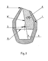
- Figure 1 is a view of the retort in elevation section through a median plane perpendicular to the horizontal axis of tilting.
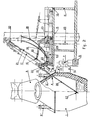
- FIG. 2 represents, in elevation, a refining installation according to the invention.
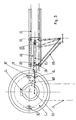
- Figure 3 shows this installation, plan view.
- the reference 1 generally designates the retort of a converter of the A.O.D. type.
- Reference 2 designates the nozzle and reference 3 a tilting journal.
- the oxygen blowing is carried out from below by means of a set of horizontal nozzles.
- Line X-X indicates the axis of one of them which is located in the plane of the figure.
- the nozzles pass through the wall of the retort 1 over an angular distance of 120 ° for example.
- Line N denotes the level of the bath being refined, while line N 'denotes the level of the bath in the pouring position.
- An orifice 4 is made through the wall of the retort which is never wet.
- This orifice provided for the passage of a temperature measurement and / or sampling rod has an oblong shape in order to take account of a certain tilting of the retort in service.
- the tilting angle is of the order of 10 °, ie 5 ° on either side of the vertical position of the retort as shown in the figure.
- the converter comprises a hood 5, a belt 6 and two bearings, such as 7, supporting the pivot pins 3.
- the belt 6 and the bearing cooperating with the bearing 7 have not shown in Figure 2, to the left of the retort 1.
- On this side of the retort are also provided a drive motor and a speed reducer of the usual types, not shown, which are mounted, as are the bearings, on a fixed structure 8 supporting the installation.
- the retort 1 is also provided with two suspenders 9 'and 9 "constituting hooking elements for a lifting machine.
- the reference 10 designates a carriage movable in translation along a horizontal track secured to the structure 8 by means of posts such as 11.
- This horizontal track is advantageously constituted by two beams 12 on which rollers 13 are fitted which equip the carriage 10.
- At least two of these rollers, those at the rear end, shown on the right in the drawings, are for example drive rollers.
- the carriage 10 carries an upright 14 at the upper end of which is articulated a cylinder 15.
- the rod of this cylinder is articulated at 16 to an inclined frame 17 which will be discussed in more detail below.
- the chassis 17 is articulated, moreover, on a horizontal axis 18 integral with the front part of the carriage 10.
- the chassis 17 constitutes a rolling track for a carriage 19 mounted on rollers 20.
- the movement of the carriage 19 is controlled by a cable 21 which passes over a pulley 22 mounted on the rear end of the chassis 17, then over a pulley 23 mounted on the front part of the carriage 10, the pulley 23 being advantageously mounted around the axis 18, then wraps around a winch 24 mounted at the rear part of the carriage 10.
- the winch 24 is controlled by a geared motor group 25 also carried by the carriage 10.
- the carriage 19 supports a pole 26 at the end of which is mounted a cartridge 27 for measuring the temperature of the bath of liquid steel contained in the retort 1.
- This pole is arranged parallel to the direction of the chassis 17 whose inclination allows the pole 26 to enter the retort 1 through the orifice 4.
- the pole 26 is advantageously made in a tubular form.
- Hoses, such as 28, make it possible to establish a circulation of water and thus ensure the internal cooling of the pole 26, and consequently its good resistance to the intense radiation of the bath.
- the winch 24 is controlled which, by means of the cable 21, causes the carriage 19 to rise along the chassis 17.
- the carriage 19 reaches its end-of-travel position, the pole 26 is extracted from the retort 1.
- the movement of the carriage 10 is then controlled, which drives the chassis 17 and the pole 26 in translation towards the right part of FIGS. 2 and 3.
- the actuator 15 is controlled. which switches the frame 17 from the oblique position to the vertical position.
- the carriage 19 can then be lowered so that the end of the pole 26, passing between the two beams 12, enters a station 29 defined by the structure of the installation. Inside this station, it is easy to replace the cartridge 27 extracted from the liquid metal bath with a new cartridge in order to carry out a new measurement.
- the various elements of the device then occupy the positions shown in broken lines in FIGS. 2 and 3.
- the installation is strictly identical in the case where the pole 26, instead of carrying a temperature measuring member such as the aforementioned cartridge, carries at its end a member for taking a sample of liquid metal sample or a combined member allowing 'carry out both operations simultaneously.
- the vertical plane containing the geometric axis of the pole is distinct from the vertical plane containing the geometric axis of the axis of tilting of the retort 1 in which the lance is disposed in the central position. As can be seen in FIG. 3, these two planes are here parallel.
- the orifice 4 is always located, in plan, in the southeast quadrant of the horizontal section of the retort 1.
- the two north quadrants correspond to areas wetted by the liquid.
- the arrangement in the southwest quadrant, although theoretically possible, is practically made impossible by the presence, on this side of retort 1, of the control members of said retort.
- the angular position of the orifice 4, inside its quadrant must correspond to an angleoC of less than 90 °, taking into account the presence of the hood 5.
- the limit value of the angle cC is practically 60 °, said angle being defined by the projection onto a horizontal plane of the geometric tilt axis and of the straight line joining the center of the orifice 4 to the center of the cross section of the retort 1.
Applications Claiming Priority (2)
| Application Number | Priority Date | Filing Date | Title |
|---|---|---|---|
| FR8121030 | 1981-11-10 | ||
| FR8121030A FR2516095A1 (fr) | 1981-11-10 | 1981-11-10 | Installation d'affinage equipee d'un dispositif de mesure de la temperature et/ou de prelevement d'echantillons d'un bain d'acier liquide |
Publications (1)
| Publication Number | Publication Date |
|---|---|
| EP0079290A1 true EP0079290A1 (de) | 1983-05-18 |
Family
ID=9263868
Family Applications (1)
| Application Number | Title | Priority Date | Filing Date |
|---|---|---|---|
| EP82402052A Withdrawn EP0079290A1 (de) | 1981-11-10 | 1982-11-08 | Vorrichtung zum Temperaturmessen und/oder Probenehmen bei einer Frischeinrichtung |
Country Status (2)
| Country | Link |
|---|---|
| EP (1) | EP0079290A1 (de) |
| FR (1) | FR2516095A1 (de) |
Cited By (8)
| Publication number | Priority date | Publication date | Assignee | Title |
|---|---|---|---|---|
| DE3834245A1 (de) * | 1988-10-07 | 1990-04-12 | Voest Alpine Ind Anlagen | Vorrichtung zur diskontinuierlichen messdatenerfassung der schmelze |
| EP0424354A1 (de) * | 1989-10-14 | 1991-04-24 | VOEST-ALPINE Industrieanlagenbau GmbH | Stahlwerkskonverter |
| DE4003068C1 (de) * | 1990-02-02 | 1991-07-25 | Voest-Alpine Industrieanlagenbau Ges.M.B.H., Linz, At | |
| DE4036216C1 (de) * | 1990-11-14 | 1992-01-30 | Voest-Alpine Industrieanlagenbau Ges.M.B.H., Linz, At | |
| DE4220306A1 (de) * | 1991-07-16 | 1993-01-21 | Voest Alpine Ind Anlagen | Einrichtung zum freihalten einer lanzenoeffnung eines metallurgischen gefaesses |
| US5259591A (en) * | 1990-02-02 | 1993-11-09 | Voest-Alpine Industrieanlagenbau Gmbh | Method for installing and removing a lance into and from a metallurgical vessel |
| WO1995029263A1 (de) * | 1994-04-22 | 1995-11-02 | Voest-Alpine Industrieanlagenbau Gmbh | Einrichtung zum einbringen einer lanze in ein metallurgisches gefäss |
| WO2017046453A1 (en) * | 2015-09-15 | 2017-03-23 | Outotec (Finland) Oy | Method and arrangement for monitoring characteristics of a furnace process in a furnace space and process monitoring unit |
Citations (4)
| Publication number | Priority date | Publication date | Assignee | Title |
|---|---|---|---|---|
| US3717034A (en) * | 1971-02-12 | 1973-02-20 | Steel Corp | Apparatus for immersing and withdrawing bath examination means into and from a molten bath |
| US3830480A (en) * | 1973-05-29 | 1974-08-20 | Steel Corp | Probe assembly |
| US3920447A (en) * | 1972-02-28 | 1975-11-18 | Pennsylvania Engineering Corp | Steel production method |
| DE2521833A1 (de) * | 1975-05-16 | 1976-11-25 | Krupp Gmbh | Verfahren zum diskontinuierlichen messen in der schmelze eines tiegels und/oder entnehmen von proben aus dem tiegel und einrichtung zur durchfuehrung des verfahrens |
-
1981
- 1981-11-10 FR FR8121030A patent/FR2516095A1/fr active Granted
-
1982
- 1982-11-08 EP EP82402052A patent/EP0079290A1/de not_active Withdrawn
Patent Citations (4)
| Publication number | Priority date | Publication date | Assignee | Title |
|---|---|---|---|---|
| US3717034A (en) * | 1971-02-12 | 1973-02-20 | Steel Corp | Apparatus for immersing and withdrawing bath examination means into and from a molten bath |
| US3920447A (en) * | 1972-02-28 | 1975-11-18 | Pennsylvania Engineering Corp | Steel production method |
| US3830480A (en) * | 1973-05-29 | 1974-08-20 | Steel Corp | Probe assembly |
| DE2521833A1 (de) * | 1975-05-16 | 1976-11-25 | Krupp Gmbh | Verfahren zum diskontinuierlichen messen in der schmelze eines tiegels und/oder entnehmen von proben aus dem tiegel und einrichtung zur durchfuehrung des verfahrens |
Cited By (19)
| Publication number | Priority date | Publication date | Assignee | Title |
|---|---|---|---|---|
| EP0364825A1 (de) * | 1988-10-07 | 1990-04-25 | VOEST-ALPINE INDUSTRIEANLAGENBAU GESELLSCHAFT m.b.H. | Vorrichtung zur diskontinuierlichen Messdatenerfassung der Schmelze |
| DE3834245A1 (de) * | 1988-10-07 | 1990-04-12 | Voest Alpine Ind Anlagen | Vorrichtung zur diskontinuierlichen messdatenerfassung der schmelze |
| EP0424354A1 (de) * | 1989-10-14 | 1991-04-24 | VOEST-ALPINE Industrieanlagenbau GmbH | Stahlwerkskonverter |
| US5096165A (en) * | 1989-10-14 | 1992-03-17 | Voest-Alpine Industrieanlagenbau Gesellschaft M.B.H. | Metallurgical vessel with probe opening |
| TR26915A (tr) * | 1990-02-02 | 1994-08-22 | Voest Alpine Ind Anlagen | Metalurji teknesine bir mizragin monte edilmesi ve cikarilmasi icin bir düzenleme ve bunun icin bir yöntem. |
| DE4003068C1 (de) * | 1990-02-02 | 1991-07-25 | Voest-Alpine Industrieanlagenbau Ges.M.B.H., Linz, At | |
| EP0444006A1 (de) * | 1990-02-02 | 1991-08-28 | Voest-Alpine Industrieanlagenbau Gmbh | Einrichtung zum Ein- und Ausbringen einer Lanze in ein und aus einem metallurgischen Gefäss |
| US5259591A (en) * | 1990-02-02 | 1993-11-09 | Voest-Alpine Industrieanlagenbau Gmbh | Method for installing and removing a lance into and from a metallurgical vessel |
| DE4036216C1 (de) * | 1990-11-14 | 1992-01-30 | Voest-Alpine Industrieanlagenbau Ges.M.B.H., Linz, At | |
| EP0486462A1 (de) * | 1990-11-14 | 1992-05-20 | VOEST-ALPINE Industrieanlagenbau GmbH | Verfahren und Einrichtung zum Verhindern einer Anlagerung von Ansätzen in einem metallurgischen Gefäss |
| US5234200A (en) * | 1990-11-14 | 1993-08-10 | Voest-Alpine Industrieanlagenbau Gmbh | Method and arrangement for preventing crusts from agglomeration in a metallurgical vessel |
| DE4220306A1 (de) * | 1991-07-16 | 1993-01-21 | Voest Alpine Ind Anlagen | Einrichtung zum freihalten einer lanzenoeffnung eines metallurgischen gefaesses |
| WO1995029263A1 (de) * | 1994-04-22 | 1995-11-02 | Voest-Alpine Industrieanlagenbau Gmbh | Einrichtung zum einbringen einer lanze in ein metallurgisches gefäss |
| WO2017046453A1 (en) * | 2015-09-15 | 2017-03-23 | Outotec (Finland) Oy | Method and arrangement for monitoring characteristics of a furnace process in a furnace space and process monitoring unit |
| CN107949760A (zh) * | 2015-09-15 | 2018-04-20 | 奥图泰(芬兰)公司 | 用于监测炉空间中的炉工艺的特征的方法和装置以及工艺监测单元 |
| EP3350527B1 (de) | 2015-09-15 | 2019-06-19 | Outotec (Finland) Oy | Verfahren und anordnung zur überwachung von eigenschaften eines ofenprozesses in einem ofenraum |
| CN107949760B (zh) * | 2015-09-15 | 2019-12-06 | 奥图泰(芬兰)公司 | 用于监测炉空间中的炉工艺的特征的方法和装置以及工艺监测单元 |
| EA035538B1 (ru) * | 2015-09-15 | 2020-07-01 | Оутотек (Финлэнд) Ой | Способ и устройство для контроля характеристик технологического процесса в печном пространстве и блок контроля за ходом технологического процесса |
| US10921061B2 (en) | 2015-09-15 | 2021-02-16 | Outotec (Finland) Oy | Method and arrangement for monitoring characteristics of a furnace process in a furnace space and process monitoring unit |
Also Published As
| Publication number | Publication date |
|---|---|
| FR2516095B1 (de) | 1984-01-06 |
| FR2516095A1 (fr) | 1983-05-13 |
Similar Documents
| Publication | Publication Date | Title |
|---|---|---|
| EP0192019A1 (de) | Vorrichtung zur Zuführung und Auswechselung einer Giessdüse | |
| EP0220543A1 (de) | Vorrichtung zum Zustellen der Wände eines Bauwerkes | |
| FR2634544A1 (fr) | Dispositif de manutention d'une goulotte de distribution d'un four a cuve et mecanisme d'entrainement adapte a ce dispositif | |
| EP0079290A1 (de) | Vorrichtung zum Temperaturmessen und/oder Probenehmen bei einer Frischeinrichtung | |
| FR2514370A1 (fr) | Dispositif pour le traitement, au passage, d'un courant de metal ou alliage liquide a base d'aluminium ou de magnesium | |
| EP1129221B1 (de) | Verteilerschurre für schüttgut | |
| EP0230180B1 (de) | Verfahren und Vorrichtung zum Unterhalten der Auskleidung eines Ofengefässes | |
| BE897688A (fr) | Appareil de raclage de scories | |
| WO1992010594A1 (fr) | Installation de production de metal fondu dans un four electrique | |
| EP0767843B1 (de) | Verfahren und vorrichtung zum beschicken eines elektroofens mit flüssigmetall | |
| EP0160593B1 (de) | Vorrichtung zur Handhabung eines Schutzrohres für einen Giessstrahl | |
| JPH063068A (ja) | 溶湯スラグ除去装置 | |
| EP0572290B1 (de) | Verfahren und Vorrichtung zum Beschicken eines Zinkingots in einer Zinkschmelze einer Verzinkungsanlage | |
| FR2574773A1 (fr) | Chariot de reception et de transport d'une piece de tricot pour metiers circulaires | |
| EP0778098B1 (de) | Elektromagnetische Rühreinrichtung für das Stranggiessen | |
| FR2565138A1 (fr) | Installation d'alimentation en fonte liquide d'une machine de coulee centrifuge | |
| WO1980000136A1 (fr) | Procede et dispositif de manutention en fonderie | |
| EP0064418B1 (de) | Einrichtung zur Stahlherstellung, bestehend aus einem Konverter, einer Abgashaube und einer Sauerstofflanze | |
| EP0034550B1 (de) | Transporteinrichtung für Barren | |
| EP0217710A1 (de) | Temperaturmessvorrichtung und/oder Probennehmer für ein Flüssigeisenbad | |
| CH509846A (fr) | Installation pour la fusion et la coulée des métaux | |
| BE1011299A6 (fr) | Appareil de manutention automatique d'un tube de coulee. | |
| FR2674946A1 (fr) | Four electrique de production de metal. | |
| BE826455A (fr) | Perfectionnements aux dispositifs destines a effectuer des prelevements d'echantillons metalliques fondus et/ou des mesures dans des bains metalliques liquides | |
| EP0006781B1 (de) | Vorrichtung zum Einführen eines Anfahrstranges bei einer Stranggiesseinrichtung |
Legal Events
| Date | Code | Title | Description |
|---|---|---|---|
| PUAI | Public reference made under article 153(3) epc to a published international application that has entered the european phase |
Free format text: ORIGINAL CODE: 0009012 |
|
| AK | Designated contracting states |
Designated state(s): AT BE CH DE GB IT LI SE |
|
| 17P | Request for examination filed |
Effective date: 19830722 |
|
| STAA | Information on the status of an ep patent application or granted ep patent |
Free format text: STATUS: THE APPLICATION HAS BEEN WITHDRAWN |
|
| 18W | Application withdrawn |
Withdrawal date: 19860411 |
|
| RIN1 | Information on inventor provided before grant (corrected) |
Inventor name: MENU, EDOUARD |