EP0159986B1 - Verfahren zur Herstellung eines Wärmeaustauschers - Google Patents
Verfahren zur Herstellung eines Wärmeaustauschers Download PDFInfo
- Publication number
- EP0159986B1 EP0159986B1 EP84900121A EP84900121A EP0159986B1 EP 0159986 B1 EP0159986 B1 EP 0159986B1 EP 84900121 A EP84900121 A EP 84900121A EP 84900121 A EP84900121 A EP 84900121A EP 0159986 B1 EP0159986 B1 EP 0159986B1
- Authority
- EP
- European Patent Office
- Prior art keywords
- webs
- heat exchanger
- web
- winding
- corrugations
- Prior art date
- Legal status (The legal status is an assumption and is not a legal conclusion. Google has not performed a legal analysis and makes no representation as to the accuracy of the status listed.)
- Expired
Links
Images

Classifications
-
- B—PERFORMING OPERATIONS; TRANSPORTING
- B21—MECHANICAL METAL-WORKING WITHOUT ESSENTIALLY REMOVING MATERIAL; PUNCHING METAL
- B21D—WORKING OR PROCESSING OF SHEET METAL OR METAL TUBES, RODS OR PROFILES WITHOUT ESSENTIALLY REMOVING MATERIAL; PUNCHING METAL
- B21D53/00—Making other particular articles
- B21D53/02—Making other particular articles heat exchangers or parts thereof, e.g. radiators, condensers fins, headers
- B21D53/027—Making other particular articles heat exchangers or parts thereof, e.g. radiators, condensers fins, headers by helically or spirally winding elongated elements
-
- F—MECHANICAL ENGINEERING; LIGHTING; HEATING; WEAPONS; BLASTING
- F28—HEAT EXCHANGE IN GENERAL
- F28D—HEAT-EXCHANGE APPARATUS, NOT PROVIDED FOR IN ANOTHER SUBCLASS, IN WHICH THE HEAT-EXCHANGE MEDIA DO NOT COME INTO DIRECT CONTACT
- F28D19/00—Regenerative heat-exchange apparatus in which the intermediate heat-transfer medium or body is moved successively into contact with each heat-exchange medium
- F28D19/04—Regenerative heat-exchange apparatus in which the intermediate heat-transfer medium or body is moved successively into contact with each heat-exchange medium using rigid bodies, e.g. mounted on a movable carrier
- F28D19/041—Regenerative heat-exchange apparatus in which the intermediate heat-transfer medium or body is moved successively into contact with each heat-exchange medium using rigid bodies, e.g. mounted on a movable carrier with axial flow through the intermediate heat-transfer medium
- F28D19/042—Rotors; Assemblies of heat absorbing masses
-
- Y—GENERAL TAGGING OF NEW TECHNOLOGICAL DEVELOPMENTS; GENERAL TAGGING OF CROSS-SECTIONAL TECHNOLOGIES SPANNING OVER SEVERAL SECTIONS OF THE IPC; TECHNICAL SUBJECTS COVERED BY FORMER USPC CROSS-REFERENCE ART COLLECTIONS [XRACs] AND DIGESTS
- Y10—TECHNICAL SUBJECTS COVERED BY FORMER USPC
- Y10S—TECHNICAL SUBJECTS COVERED BY FORMER USPC CROSS-REFERENCE ART COLLECTIONS [XRACs] AND DIGESTS
- Y10S165/00—Heat exchange
- Y10S165/009—Heat exchange having a solid heat storage mass for absorbing heat from one fluid and releasing it to another, i.e. regenerator
- Y10S165/042—Particular structure of heat storage mass
Definitions
- the subject invention relates to a method of manufacturing a heat exchanger comprising two metal webs one of them formed with corrugations forming channels throughout the heat exchanger.
- Heat exchangers of the kind contemplated herein comprise two metal webs, preferably of aluminium, which webs are arranged in superposed relationship and wound about a core.
- One of the webs is provided with corrugations extending in the crosswise direction of the web so as to form channels which extend through the heat exchanger.
- the heat exchanger forms a rotating wheel, wherein the exchange of the heat is obtained by rotating the wheel between flows of fluid of different temperatures so that said fluid flows are heated or cooled by the walls of said channels.
- Heat exchangers of the type concerned herein are known since 1924.
- recovery of heat/cold with the aid of ventilation air wheels of this kind began to be used to an increasing degree after the second World War.
- the energy crisis of 1975 has speeded up the use further.
- the problems arising in the manufacture of wheels of this kind are mainly concerned with the glue. It has to be applied very exactly on the crests of the pleats.
- the glue must not spread or be pulled out during the winding-on operation. After the winding-on operation the wheel must be transferred to an oven, wherein the glue is allowed to set.
- the glue serves as a lubricant encouraging movement between the pleats and the plane foil, which makes the handling of the wheel delicate.
- excess glue has a tendency to spread and block the channels to a larger or smaller extent.
- the glue may also be the cause of exzema, allergies and other similar serious illnesses which are difficult to remedy.
- a small (often invisible) fault in the glue bond may easily cause the total collapse of the wheel. It is therefore necessary to test the wheels carefully for strength before they are installed.
- the safest (but also the most expensive) way of solving the problem is to cut the wheel into segments, after the gluing operation, and to insert the segments in self-supporting frames.
- the method is very complicated and expensive.
- Another method uses 4 to 8 spokes which are inserted into channels milled into the two faces of the wheel to take the majority of the strain. This method is used predominantly in smaller wheels having a maximum diameter of about 1.5 to 2 meters.
- a third method also uses 4 to 8 spokes which are hammered or drilled diametrically through the wheels after the wheel-glueing operation. This method is used generally by several manufacturers.
- the purpose of the subject invention is to solve the above problems found in heat exchange rolls in which glue bonds are used.
- This is achieved in accordance with the teachings of the invention in that the corrugations are formed in the first one of the webs, the two webs are winded on a core in superposed relationship and the second one of said webs is stretched during the winding-on in order to create a strong tension in said second web.
- glue bonds become superfluous and the disadvantages described above in connection with prior-art technique are eliminated.
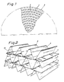
- the heat exchanger in accordance with the invention referred to as a unit by numeral reference 2, consists of two webs 4 and 6 of aluminium which are wound about each other in superposed relationship.
- the web 4 is formed with corrugations comprising ridges 8 and depressions 10.
- the other web 6 is plane (straight) in accordance with the embodiment shown in Figs. 1 and 2.
- the corrugations form channels extending throughout the heat exchanger allowing through-flow of fluids (primarily ventilation air).
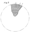
- Figs. 3 and 4 show a heat exchanger in accordance with a second embodiment of the invention according to which the second web, in this case referred to by numeral 12, is given a wavy configuration with the waves extending in the lengthwise direction.
- the two webs are produced in a prior-art manner, see EP-A-52 592.
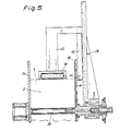
- Fig. 6 shows one example of production of the heat exchanger.
- the web 4 is wound off a rotating roll 14, is fed up to a corrugating station 16, wherein it passes through the nip of rollers 18, 20 which are provided with interengaging cogs, the latter extending in the axial direction of the rollers.
- the web 4 is then advanced across a plate 22 and further up between two guide or master rollers 24, 26 to the winding-on station 28.
- the second web 6 or 12 is supplied from a rotating roll 30 and advanced up to the winding-on station 28 wherein the two webs are wound about each other.
- This tension preferably has a magnitude of at least 100 kp for a foil of width of 250 mm ( ⁇ 6 kp mm 2 ) in order to impart the desired strength to the heat exchanger roll.
- the aluminium foil has a thickness of appr. 60 p (the cross-sectional diameter thus will be 15 mm 2 ).
- Fig. 5 shows one embodiment, cf SE-A-424 277, of a winding-on station 28.
- the latter comprises a core sleeve 32, onto which the two webs are wound.
- the winding-on operation takes place between two end walls 34, 36.
- One, 34, of the end walls is arranged to be folded outwards after the winding-on of the webs to remove the finished heat exchanger roll 2, while the opposite wall 36 rotates together with the core sleeve 32, which is driven in any suitable manner, such as by belt or cog-wheel drive.
- a roller 38 presses against the outermost web 6 and arms 40, 42 are provided to attach the roller to the rear face of the end wall 36.
- the high tension in the second web 6 or 12 and the friction between the corrugated web 4 and the second web 6 or 12 has the effect that the heat exchanger 2, when in its completed condition, does not collapse in operation as a result of the two webs 4 and 6 or 4 and 12 sliding apart when exposed to the axial pressures (i.e. axial in relation to the finished wheel) generated by the flows of air.
- the coefficient of friction between two layers of aluminium normally is about 0.3 but by surface-treating the webs such as by roughing, knurling, etching or by using other surface-treatment methods, the coefficient may be increased to about 0.8.
- the second web 12 has a wavy configuration in its lengthwise direction in the manner appearing from Fig. 4, a comparatively secure bond (cf Fig. 4) is obtained between the two webs.
- the highly tensioned web 12 presses into the ridges 8 and the depressions 10 in the web 4, impressing dents therein matching the waves formed in the web 12. This further increases the bond between the webs.
Landscapes
- Engineering & Computer Science (AREA)
- Mechanical Engineering (AREA)
- Physics & Mathematics (AREA)
- Thermal Sciences (AREA)
- General Engineering & Computer Science (AREA)
- Heat-Exchange Devices With Radiators And Conduit Assemblies (AREA)
- Materials For Medical Uses (AREA)
- Nonwoven Fabrics (AREA)
- Moulding By Coating Moulds (AREA)
- Heating, Cooling, Or Curing Plastics Or The Like In General (AREA)
- Gloves (AREA)
- Surgical Instruments (AREA)
- Non-Silver Salt Photosensitive Materials And Non-Silver Salt Photography (AREA)
- Organic Low-Molecular-Weight Compounds And Preparation Thereof (AREA)
- Absorbent Articles And Supports Therefor (AREA)
- Shaping Of Tube Ends By Bending Or Straightening (AREA)
Claims (2)
Priority Applications (1)
| Application Number | Priority Date | Filing Date | Title |
|---|---|---|---|
| AT84900121T ATE28512T1 (de) | 1982-11-30 | 1983-11-29 | Verfahren zur herstellung eines waermeaustauschers. |
Applications Claiming Priority (2)
| Application Number | Priority Date | Filing Date | Title |
|---|---|---|---|
| SE8206809A SE8206809L (sv) | 1982-11-30 | 1982-11-30 | Vermevexlare |
| SE8206809 | 1982-11-30 |
Publications (2)
| Publication Number | Publication Date |
|---|---|
| EP0159986A1 EP0159986A1 (de) | 1985-11-06 |
| EP0159986B1 true EP0159986B1 (de) | 1987-07-22 |
Family
ID=20348793
Family Applications (1)
| Application Number | Title | Priority Date | Filing Date |
|---|---|---|---|
| EP84900121A Expired EP0159986B1 (de) | 1982-11-30 | 1983-11-29 | Verfahren zur Herstellung eines Wärmeaustauschers |
Country Status (10)
| Country | Link |
|---|---|
| US (1) | US4633936A (de) |
| EP (1) | EP0159986B1 (de) |
| JP (1) | JPS59502117A (de) |
| AT (1) | ATE28512T1 (de) |
| AU (1) | AU2337684A (de) |
| DE (1) | DE3372661D1 (de) |
| DK (1) | DK154917C (de) |
| NO (1) | NO160234C (de) |
| SE (1) | SE8206809L (de) |
| WO (1) | WO1984002179A1 (de) |
Families Citing this family (16)
| Publication number | Priority date | Publication date | Assignee | Title |
|---|---|---|---|---|
| US5085268A (en) * | 1980-11-14 | 1992-02-04 | Nilsson Sven M | Heat transmission roll and a method and an apparatus for manufacturing such a roll |
| US5987882A (en) * | 1996-04-19 | 1999-11-23 | Engelhard Corporation | System for reduction of harmful exhaust emissions from diesel engines |
| US6422008B2 (en) | 1996-04-19 | 2002-07-23 | Engelhard Corporation | System for reduction of harmful exhaust emissions from diesel engines |
| US5803158A (en) * | 1996-10-04 | 1998-09-08 | Abb Air Preheater, Inc. | Air preheater heat transfer surface |
| US6655369B2 (en) * | 2001-08-01 | 2003-12-02 | Diesel Engine Transformations Llc | Catalytic combustion surfaces and method for creating catalytic combustion surfaces |
| US6588221B1 (en) | 2002-10-23 | 2003-07-08 | Super S.E.E.R Systems Inc. | Refrigeration system with dedicated compressor for hot gas defrost |
| ATE347076T1 (de) * | 2003-10-01 | 2006-12-15 | Imes Man Ag | Vorrichtung zur entfeuchtung von raumluft |
| US20060198736A1 (en) * | 2005-03-01 | 2006-09-07 | Caterpillar Inc. | Pump control system for variable displacement pump |
| DE102006003317B4 (de) | 2006-01-23 | 2008-10-02 | Alstom Technology Ltd. | Rohrbündel-Wärmetauscher |
| US9557119B2 (en) | 2009-05-08 | 2017-01-31 | Arvos Inc. | Heat transfer sheet for rotary regenerative heat exchanger |
| US8622115B2 (en) * | 2009-08-19 | 2014-01-07 | Alstom Technology Ltd | Heat transfer element for a rotary regenerative heat exchanger |
| US9200853B2 (en) | 2012-08-23 | 2015-12-01 | Arvos Technology Limited | Heat transfer assembly for rotary regenerative preheater |
| US10175006B2 (en) | 2013-11-25 | 2019-01-08 | Arvos Ljungstrom Llc | Heat transfer elements for a closed channel rotary regenerative air preheater |
| US10094626B2 (en) | 2015-10-07 | 2018-10-09 | Arvos Ljungstrom Llc | Alternating notch configuration for spacing heat transfer sheets |
| PL235069B1 (pl) | 2017-12-04 | 2020-05-18 | Ts Group Spolka Z Ograniczona Odpowiedzialnoscia | Zwój do transmisji ciepła dla obrotowego cylindrycznego wymiennika ciepła |
| DE102020207292A1 (de) | 2020-06-10 | 2021-12-16 | Vitesco Technologies GmbH | Rotationswärmetauscher |
Family Cites Families (10)
| Publication number | Priority date | Publication date | Assignee | Title |
|---|---|---|---|---|
| GB311889A (en) * | 1928-04-02 | 1929-05-23 | Frank Bailey | Improvements in apparatus for use in effecting the exchange of heat between fluids |
| US3290764A (en) * | 1963-03-04 | 1966-12-13 | Air Preheater | Continuously wrapped rotor |
| US3532157A (en) * | 1969-01-03 | 1970-10-06 | Gen Motors Corp | Regenerator disk |
| DE2007956A1 (de) * | 1970-02-20 | 1971-09-02 | Linde Ag | Regenerator |
| US3901309A (en) * | 1974-05-16 | 1975-08-26 | Gen Motors Corp | Regenerator disk flexible rim |
| US3975662A (en) * | 1975-02-10 | 1976-08-17 | Sanders Associates, Inc. | Off-center radar display circuit |
| SE412023B (sv) * | 1976-05-19 | 1980-02-18 | Munters Ab Carl | Sett och anordning for att framstella en rotor for en fukt- och/eller vermevexlare |
| CH628730A5 (de) * | 1977-06-02 | 1982-03-15 | Alusuisse | Band zur herstellung von koerpern zum austausch von fuehlbarer und latenter waerme in einem regenerativen waermeaustauscher. |
| SE424277B (sv) * | 1980-11-14 | 1982-07-12 | Sven Melker Nilsson | Forfarande och maskin for framstellning av rullar av pa varandra limmade banor, av vilka den ena er korrugerad |
| US4307774A (en) * | 1980-11-20 | 1981-12-29 | Konstantins Dravnieks | Heat wheel construction |
-
1982
- 1982-11-30 SE SE8206809A patent/SE8206809L/xx unknown
-
1983
- 1983-11-29 DE DE8484900121T patent/DE3372661D1/de not_active Expired
- 1983-11-29 WO PCT/SE1983/000415 patent/WO1984002179A1/en not_active Ceased
- 1983-11-29 EP EP84900121A patent/EP0159986B1/de not_active Expired
- 1983-11-29 AU AU23376/84A patent/AU2337684A/en not_active Abandoned
- 1983-11-29 AT AT84900121T patent/ATE28512T1/de not_active IP Right Cessation
- 1983-11-29 US US06/638,466 patent/US4633936A/en not_active Expired - Lifetime
- 1983-11-29 JP JP84500119A patent/JPS59502117A/ja active Pending
-
1984
- 1984-07-25 NO NO84843025A patent/NO160234C/no unknown
- 1984-07-27 DK DK366984A patent/DK154917C/da not_active IP Right Cessation
Also Published As
| Publication number | Publication date |
|---|---|
| ATE28512T1 (de) | 1987-08-15 |
| SE8206809D0 (sv) | 1982-11-30 |
| DE3372661D1 (en) | 1987-08-27 |
| SE8206809L (sv) | 1984-05-31 |
| WO1984002179A1 (en) | 1984-06-07 |
| DK366984A (da) | 1984-07-27 |
| US4633936A (en) | 1987-01-06 |
| DK154917B (da) | 1989-01-02 |
| JPS59502117A (ja) | 1984-12-20 |
| DK366984D0 (da) | 1984-07-27 |
| NO160234C (no) | 1989-03-22 |
| EP0159986A1 (de) | 1985-11-06 |
| DK154917C (da) | 1989-07-03 |
| NO160234B (no) | 1988-12-12 |
| NO843025L (no) | 1984-07-25 |
| AU2337684A (en) | 1984-06-18 |
Similar Documents
| Publication | Publication Date | Title |
|---|---|---|
| EP0159986B1 (de) | Verfahren zur Herstellung eines Wärmeaustauschers | |
| US6053232A (en) | Embossing and laminating machine with embossing cylinders having different rotational speed | |
| US2581421A (en) | Method and apparatus for making structural elements | |
| KR20140136018A (ko) | 단일면 골판지 제조방법 | |
| JP2005178909A (ja) | 複数重ね部からなる直線引出し支柱 | |
| HK1006556B (en) | Improved method for manufacturing a laminate having at least ione pleated lamina | |
| HK1006556A1 (en) | Improved method for manufacturing a laminate having at least ione pleated lamina | |
| US5085268A (en) | Heat transmission roll and a method and an apparatus for manufacturing such a roll | |
| CN1156983A (zh) | 一种制造层压复合材料的方法 | |
| JPH0631711B2 (ja) | 熱交換器の製造法 | |
| JP3517110B2 (ja) | 片面段ボール製造方法および装置 | |
| EP2846063B1 (de) | Installationsvorrichtung für einen Trommelbelag | |
| EP0052592B1 (de) | Wärmeübertragungsrolle und Verfahren und Vorrichtung zu deren Herstellung | |
| US5996246A (en) | Edge seal for vacuum preheater | |
| US8128544B2 (en) | Low inertia roll | |
| AU2615284A (en) | Manufacture of heat exchanger rolls | |
| JPH032055B2 (de) | ||
| US11850651B2 (en) | Method of manufacturing a heat-humidity exchange plate of an enthalpy air-to-air exchanger | |
| JPH01295838A (ja) | 複合コルゲート体の製造方法並びに製造装置 | |
| JP3509801B2 (ja) | 段ボールシートの反り防止装置 | |
| JP3020528U (ja) | 片面段ボール製造装置 | |
| JP3501251B2 (ja) | 片面段ボール製造装置 | |
| JPH0521063B2 (de) | ||
| JPS59124842A (ja) | コ−ルドコルゲ−タ | |
| JPS58187337A (ja) | エンボス紙の加工方法 |
Legal Events
| Date | Code | Title | Description |
|---|---|---|---|
| PUAI | Public reference made under article 153(3) epc to a published international application that has entered the european phase |
Free format text: ORIGINAL CODE: 0009012 |
|
| 17P | Request for examination filed |
Effective date: 19841228 |
|
| AK | Designated contracting states |
Designated state(s): AT BE DE FR GB LU NL |
|
| 17Q | First examination report despatched |
Effective date: 19860402 |
|
| GRAA | (expected) grant |
Free format text: ORIGINAL CODE: 0009210 |
|
| AK | Designated contracting states |
Kind code of ref document: B1 Designated state(s): AT BE DE FR GB LU NL |
|
| PG25 | Lapsed in a contracting state [announced via postgrant information from national office to epo] |
Ref country code: NL Effective date: 19870722 Ref country code: BE Effective date: 19870722 Ref country code: AT Effective date: 19870722 |
|
| REF | Corresponds to: |
Ref document number: 28512 Country of ref document: AT Date of ref document: 19870815 Kind code of ref document: T |
|
| REF | Corresponds to: |
Ref document number: 3372661 Country of ref document: DE Date of ref document: 19870827 |
|
| PG25 | Lapsed in a contracting state [announced via postgrant information from national office to epo] |
Ref country code: LU Free format text: LAPSE BECAUSE OF NON-PAYMENT OF DUE FEES Effective date: 19871130 |
|
| ET | Fr: translation filed | ||
| NLV1 | Nl: lapsed or annulled due to failure to fulfill the requirements of art. 29p and 29m of the patents act | ||
| PLBE | No opposition filed within time limit |
Free format text: ORIGINAL CODE: 0009261 |
|
| STAA | Information on the status of an ep patent application or granted ep patent |
Free format text: STATUS: NO OPPOSITION FILED WITHIN TIME LIMIT |
|
| 26N | No opposition filed | ||
| PGFP | Annual fee paid to national office [announced via postgrant information from national office to epo] |
Ref country code: GB Payment date: 19901119 Year of fee payment: 8 |
|
| PGFP | Annual fee paid to national office [announced via postgrant information from national office to epo] |
Ref country code: DE Payment date: 19901127 Year of fee payment: 8 |
|
| PGFP | Annual fee paid to national office [announced via postgrant information from national office to epo] |
Ref country code: FR Payment date: 19901130 Year of fee payment: 8 |
|
| PG25 | Lapsed in a contracting state [announced via postgrant information from national office to epo] |
Ref country code: GB Effective date: 19911129 |
|
| GBPC | Gb: european patent ceased through non-payment of renewal fee | ||
| PG25 | Lapsed in a contracting state [announced via postgrant information from national office to epo] |
Ref country code: FR Effective date: 19920731 |
|
| PG25 | Lapsed in a contracting state [announced via postgrant information from national office to epo] |
Ref country code: DE Effective date: 19920801 |
|
| REG | Reference to a national code |
Ref country code: FR Ref legal event code: ST |