EP0158702B1 - Schwenkleitwerk für kleinkalibrige Flugkörper - Google Patents
Schwenkleitwerk für kleinkalibrige Flugkörper Download PDFInfo
- Publication number
- EP0158702B1 EP0158702B1 EP84108966A EP84108966A EP0158702B1 EP 0158702 B1 EP0158702 B1 EP 0158702B1 EP 84108966 A EP84108966 A EP 84108966A EP 84108966 A EP84108966 A EP 84108966A EP 0158702 B1 EP0158702 B1 EP 0158702B1
- Authority
- EP
- European Patent Office
- Prior art keywords
- fins
- slider
- swivel
- swung
- unit according
- Prior art date
- Legal status (The legal status is an assumption and is not a legal conclusion. Google has not performed a legal analysis and makes no representation as to the accuracy of the status listed.)
- Expired
Links
- 230000033001 locomotion Effects 0.000 claims description 8
- 210000002105 tongue Anatomy 0.000 claims description 7
- 238000005096 rolling process Methods 0.000 claims description 5
- 241000251169 Alopias vulpinus Species 0.000 claims 5
- 239000004429 Calibre Substances 0.000 claims 1
- 238000006073 displacement reaction Methods 0.000 claims 1
- 230000001133 acceleration Effects 0.000 description 2
- 238000013461 design Methods 0.000 description 2
- ZPUCINDJVBIVPJ-LJISPDSOSA-N cocaine Chemical compound O([C@H]1C[C@@H]2CC[C@@H](N2C)[C@H]1C(=O)OC)C(=O)C1=CC=CC=C1 ZPUCINDJVBIVPJ-LJISPDSOSA-N 0.000 description 1
- 230000006835 compression Effects 0.000 description 1
- 238000007906 compression Methods 0.000 description 1
- 230000003247 decreasing effect Effects 0.000 description 1
- 230000001419 dependent effect Effects 0.000 description 1
- 238000011161 development Methods 0.000 description 1
- 230000018109 developmental process Effects 0.000 description 1
- 238000003780 insertion Methods 0.000 description 1
- 230000037431 insertion Effects 0.000 description 1
- 238000000034 method Methods 0.000 description 1
- 238000012856 packing Methods 0.000 description 1
- 238000012549 training Methods 0.000 description 1
- 230000007704 transition Effects 0.000 description 1
Images

Classifications
-
- F—MECHANICAL ENGINEERING; LIGHTING; HEATING; WEAPONS; BLASTING
- F42—AMMUNITION; BLASTING
- F42B—EXPLOSIVE CHARGES, e.g. FOR BLASTING, FIREWORKS, AMMUNITION
- F42B10/00—Means for influencing, e.g. improving, the aerodynamic properties of projectiles or missiles; Arrangements on projectiles or missiles for stabilising, steering, range-reducing, range-increasing or fall-retarding
- F42B10/02—Stabilising arrangements
- F42B10/14—Stabilising arrangements using fins spread or deployed after launch, e.g. after leaving the barrel
- F42B10/18—Stabilising arrangements using fins spread or deployed after launch, e.g. after leaving the barrel using a longitudinally slidable support member
Definitions
- the invention relates to a tailplane for small-caliber missiles, projectiles or small bombs according to the preamble of claim 1.
- a wing arrangement is known for a projectile for a karoka, in particular for training purposes, in which the wings swing radially out of the projectile.
- the wings and a spring-driven sliding sleeve are designed as cam gears, with the wings being pivoted counter to the direction of flight.
- the overall length of the entire wing arrangement is relatively large.
- a missile propelled missile is known from DE-B-1231 139.
- the missile has several payload heads that can be braked separately.
- several pan wings that can be pivoted against the direction of fall are provided.
- DE-C-2227104 discloses a projectile with a tail unit that can be opened, the wings of which can be opened tangentially to the tail boom.
- the wings are fixed in the folded position by a gas pressure-dependent, multi-part locking device.
- the wings are opened by the gas pressure and / or by a compression spring via a sliding sleeve.
- the probability of failure is higher in the case of multi-part devices than in the case of one-piece devices. It is also not specified how the wings can be locked in the opened position in order to eliminate possible sources of interference, such as turbulence in the air.
- the invention has for its object to design a tailplane according to the preamble of claim 1 so that it has small dimensions, is very light to achieve a high packing density of the missiles, to optimize the payload share of the missiles consists of a few, relatively simple parts and also has precisely guided fins which, due to their limited deflectability beyond the locking mechanism, reduce impacts and impacts from turbulence in the air.
- the solution to this problem can be found in the features of the characterizing part of claim 1.
- Advantageous developments of the subject matter according to claim 1 are specified in the subclaims.
- the design principle is based on a spring-powered cam mechanism, the characteristic of which is based on the fact that after unlocking the fins, they are swung out of the inactive position with a relatively high angular acceleration, the acceleration continuously decreasing over the course of the swivel path up to the point of movement at which the swivel movement transitions in a sliding motion. This sliding movement then leads to the locking of the fins in the end position.
- the contact point of the stop ring below the axis of rotation of the fin provides the function, since when the slide is axially pressed, the roll curve can roll over this contact point and ensure that the fins can be easily swung out.
- the two-stage roll curve on the stop ring causes the fins to swing out in the first stage and in the second stage the fins are locked in the final position.
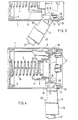
- a housing-fixed support ring 3, a helical spring 4 centered in the support ring 3, a slide 5, fins 6, an axially movable stop ring 7 and a releasable bolt 8 are arranged in a casing 1 of a small bomb 2, not shown.
- the helical spring 4 is supported centrally on the support ring 3 and acts - again centrally - against the slide 5, which has radially oriented webs 9 on its end face 12 facing the helical spring 4.
- the inner surfaces 10 of the webs 9 enclose the helical spring 4 in a centering manner, while the radially outer surfaces 11 of the webs 9 rest in axial guidance on the inner wall of the casing 1.
- the essentially annular slide 5 is provided on the end face 13 facing away from the webs 9 with axially aligned tongues 14, which are evenly distributed over the circumference and each apply between two adjacent webs 9.
- the tongues 14 are each separated by a slot 18 running parallel to the central axis, which extends radially into the annular body of the slide 5.
- the tongues 14 are further provided with tangential contact shoulders 15 which are formed transversely to the longitudinal axis of the casing 1.
- the non-rotatable but axially movable stop ring 7 has Openings 16 for receiving the tongues 14.
- the slide 5 is fixed in a rotationally fixed manner both via the tongues 14 engaging in the openings 16 and also via the fins 6 movable in the longitudinal slots 19 of the casing 1.
- the rotationally fixed mounting of the stop ring 7 is brought about by radial pins 35 which engage in the longitudinal slots 19 of the casing 1 and stop the axial movement of the stop ring 7 when they bear against the axial delimitation of the longitudinal
- the fins 6 have at one end a plugged into a through hole.
- the bearing point of the abutment shoulder 15 is delimited radially outwards by the inner wall of the casing 1.
- the fin 6 In the folded rest position, the fin 6 is in the radial slot 18 of the slider 5 and rests with a surface 20 on the axial end face 12 of the slider 5, whereby the fin 6 is secured against axial slipping.
- the nose 21 on the end edge opposite the spiral spring pin 17 the fin 6 lies in an annular recess 22 of the support ring 3 and is thereby held against radial pivoting out during its rest position.
- the width of the fin 6 is so large that the fin 6 is also guided in its rest position with the radially outer edge 23 in the longitudinal slot 19 of the casing 1 and projects slightly beyond the outer diameter of the casing 1.
- the outer edge 23 of the fin 6 merges in the area of the spiral spring pin 17 into a rolling curve 24, which in turn ends at the end edge 25 of the fin 6.
- the fin 6 With the lower part of this end edge 25, the fin 6 is axially in contact with the end face annular surface 26 of the stop ring 7.
- the contact or roll-off point 27 of the stop ring 7 lies radially below the spiral spring pin 17.
- the ring surface 26 passes at right angles via the roll-off point 27 into the slideway 28 of the opening 16 of the stop ring 7.
- the slide 5 is thin-walled overall. Through its central recess 29, which continues in the stop ring 7 via an inner cone 30, it creates a further space 31 for the insertion at the head of a further small bomb 32 indicated by a dot-dash line.
- the recess 29 in the slider 5 is designed such that it has a bearing surface for forms the impact sensor of the next small bomb 32, which remains undamaged during transport due to the coordination with the surfaces of the recess 29.
- tailplane The function of the tailplane is as follows:
- the bolt 8 is ejected by the force of the coil spring 4 via the axially moved slide 5.
- the slider 5 slides axially within the sleeve 1 in the direction of the effective force of the helical spring 4.
- the slider 5 axially hits the stop ring 7 through the end edges 25 of the fins 6, which likewise moves back a limited distance in the axial direction.
- the coil spring 4 progressively relaxes, the fins 6 slide out of the recess 22 of the support ring 3 and are released from the radial holder.
- the pivoting movement of the fins 6 takes place within the longitudinal slots 19 of the casing 1 up to the border edge 33 thereof.
- the rolling curve 24 lies with the adjoining edge 25 on the slideway 28 after the slide 5 with its tongues 14 into the corresponding openings 16 of the stop ring 7 has moved.
- the fins 6 are locked in this position against pivoting back both by the support on the slide 28 and by the force of the coil spring 4.
Landscapes
- Physics & Mathematics (AREA)
- Fluid Mechanics (AREA)
- Engineering & Computer Science (AREA)
- General Engineering & Computer Science (AREA)
- Filling Or Discharging Of Gas Storage Vessels (AREA)
- Vibration Dampers (AREA)
- Toys (AREA)
Description
- Die Erfindung bezieht sich auf ein Schwenkleitwerk für kleinkalibrige Flugkörper, Geschosse oder Kleinbomben nach dem Oberbegriff des Anspruches 1.
- Aus der DE-A-21 37 766 ist bei einem Geschoß für eine Panzerfaust, insbesondere für Übungszwecke, eine Flügelanordnung bekannt, bei der die Flügel radial aus dem Geschoß ausschwenken. Die Flügel und eine federgetriebene Schiebehülse sind als Kurvengetriebe ausgebildet, wobei die Schwenkrichtung der Flügel entgegen der Flugrichtung erfolgt. Dadurch ist die Baulänge der gesamten Flügelanordnung relativ groß.
- Aus der DE-B-1231 139 ist ein Flugkörper mit Raketenantrieb bekannt. Der Flugkörper weist mehrere, separat abbremsbare Nutzlastköpfe auf. Dazu sind mehrere, entgegen der Fallrichtung schwenkbare Schalenflügel vorgesehen.
- Aus der DE-C-2227104 ist ein Geschoß mit aufklappbarem Leitwerk bekannt, dessen Flügel tangential zum Leitwerkträger aufklappbar sind. Die Flügel sind in eingeklappter Poistion durch eine gasdruckabhängige, mehrteilige Arretiervorrichtung festgelegt. Bei vorbestimmten Gasdruck werden die Flügel durch den Gasdruck und/oder durch eine Druckfeder über eine Schiebehülse aufgeklappt. Bekanntlich ist bei mehrteiligen Vorrichtungen die Ausfallwahrscheinlichkeit höher als bei einteiligen Vorrichtungen. Auch ist nicht angegeben, auf welche Weise die Flügel in der aufgeklappten Position arretierbar sind, um mögliche Störquellen, wie Turbulenzen der Luft zu eliminieren.
- Der Erfindung liegt die Aufgabe zugrunde, ein Schwenkleitwerk entsprechend dem Oberbegriff des Anspruches 1 so auszubilden, daß es geringe Abmessungen aufweist, zur Erzielung einer hohen Packungsdichte der Flugkörper sehr leicht ausgebildet ist, zur Optimierung des Nutzlastanteils bei den Flugkörpern aus wenigen, relativ einfachen Teilen besteht und dazu präzis geführte Flossen aufweist, die durch eine begrenzte Auslenkbarkeit über die Verriegelung hinaus Stöße und Schläge von Turbulenzen der Luft abbaut. Die Lösung dieser Aufgabe ist den Merkmalen des kennzeichnenden Teiles des Anspruchs 1 zu entnehmen. Vorteilhafte Weiterbildungen des Gegenstandes nach dem Anspruch 1 sind in den Unteransprüchen angegeben.
- Das Konstruktionsprinzip beruht auf einem federkraftbetriebenen Kurvengetriebe, dessen Charakteristik darauf beruht, daß nach dem Entriegeln der Flossen dieselben mit relativ hoher Winkelbeschleunigung aus der unwirksamen Position ausgeschwenkt werden, wobei im Verlauf des Schwenkweges die Beschleunigung kontinuierlich abnimmt bis zu dem Bewegungspunkt, bei dem die Schwenkbewegung übergeht in eine Gleitbewegung. Diese Gleitbewegung führt dann zur Verriegelung der Flossen in der Endposition.
- Nach dem Anspruch 2 liegt ein einfaches Kurvengetriebe vor, das durch geringfügige, konstruktive Änderungen der an sich fürt ein Schwenkleitwerk bereits vorhandenen Elemente gebildet ist.
- Dabei gewährt gerade der unterhalb der Flossendrehachse liegende Anlagepunkt des Anschlagringes die Funktion, da bei Axialdruck des Schiebers die Rollkurve über diesen Anlagepunkt abrollen kann und ein leichtes Ausschwenken der Flossen gewährleistet.
- Die zweistufige Rollkurve an dem Anschlagring bewirkt in der ersten Stufe den eigentlichen Ausschwenkvorgang der Flossen und in der zweiten Stufe die formschlüssige Arretierung der Flossen in der Endstellung.
- Nach dem Anspruch 3 ist eine einfache Maßnahme zur Arretierung der Flossen in eingeschwenkter Position angegeben.
- Nach dem Anspruch 4 liegt eine konstruktiv einfache und kostengünstige Lagerung der Flossen an dem Schieber vor.
- Nach dem Anspruch 5 liegt eine einfache Verdrehsicherung des Schiebers vor, so daß die ausgeschwenkten Flossen in Rotationsrichtung arretiert sind.
- Ein Ausführungsbeispiel der Erfindung ist in der Zeichnung dargestellt. Es zeigt :
- Fig. 1 einen Längsschnitt aus einem Schwenkleitwerk einer Kleinbombe ;
- Fig. 2 einen Schnitt gemäß 11-11 nach Fig. 1 ;
- Fig. 3 das Schwenkleitwerk in einer Bewegungsphase während des Schwenkvorganges im Schnitt ;
- Fig. 4 das Schwenkleitwerk in der arretierten Endposition im Schnitt.
- Nach den Figuren 1 und 2 sind in einer Hülle 1 einer nicht weiter dargestellten Kleinbombe 2 ein gehäusefester Stützring 3, eine in dem Stützring 3 zentrierte Schraubenfeder 4, ein Schieber 5, Flossen 6, ein axial beweglicher Anschlagring 7 und ein lösbarer Riegel 8 angeordnet.
- Die Schraubenfeder 4 stützt sich an dem Stützring 3 zentral ab und wirkt - wiederum zentral-, gegen den Schieber 5, der an seiner der Schraubenfeder 4 zugewandten Stirnfläche 12 radial ausgerichtete Stege 9 aufweist. Die innenliegenden Flächen 10 der Stege 9 umschließen zentrierend die Schraubenfeder 4, während die radial außenliegenden Flächen 11 der Stege 9 in Axialführung an der Innenwand der Hülle 1 anliegen.
- Der im wesentlichen ringförmige Schieber 5 ist auf der den Stegen 9 abgewandten Stirnfläche 13 mit axial ausgerichteten Zungen 14 versehen, die gleichmäßig über den Umfang verteilt sind und jeweils zwischen zwei benachbarte Stege 9 ansetzen. Die Zungen 14 sind durch jeweils einen parallel zur Mittelachse verlaufenden Schlitz 18 getrennt, der sich radial bis in den ringförmigen Körper des Schiebers 5 fortsetzt. Am Außenumfang sind die Zungen 14 ferner mit quer zur Längsachse der Hülle 1 ausgebildeten, tangentialen Anlageschultern 15 versehen. Der drehfest, aber axial bewegliche Anschlagring 7 besitzt Öffnungen 16 für die Aufnahme der Zungen 14. Sowohl über die in den Öffnungen 16 eingreifenden Zungen 14 als auch über die in Längsschlitzen 19 der Hülle 1 beweglichen Flossen 6 ist der Schieber 5 verdrehfest festgelegt. Die drehfeste Halterung des Anschlagringes 7 wird durch Radialstifte 35 hervorgerufen, die in die Längsschlitze 19 der Hülle 1 eingreifen und bei Anlage an der axialen Begrenzung der Längsschlitze 19 die axiale Bewegung des Anschlagringes 7 stoppen.
- Die Flossen 6 besitzen an ihrem einen Ende einen in eine Durchgangsbohrung eingesteckten. Spiralspannstift 17, der als Lager- und Drehachse der Flossen dient und an der Anlageschulter 15 anliegt. Durch die Innenwandung der Hülle 1 ist die Lagerstelle der Anlageschulter 15 radial nach außen begrenzt. In der eingeklappten Ruhelage befindet sich die Flosse 6 in dem radialen Schlitz 18 des Schiebers 5 und liegt mit einer Fläche 20 an der axialen Stirnfläche 12 des Schiebers 5 an, wodurch die Flosse 6 gegen axiales Verrutschen gesichert ist. Mit der Nase 21 an der dem Spiralspannstift 17 entgegengesetzten Stirnkante liegt die Flosse 6 in einer ringförmigen Ausdrehung 22 des Stützringes 3 und ist dadurch während ihrer Ruhelage gegen ein radiales Ausschwenken gehalten. Die Breite der Flosse 6 ist so groß, daß die Flosse 6 auch in ihrer Ruhelage mit der radialaußenliegenden Kante 23 im Längsschlitz 19 der Hülle 1 geführt ist und leicht über den Außendurchmesser der Hülle 1 hinausragt.
- Die Außenkante 23 der Flosse 6 geht im Bereich des Spiralspannstiftes 17 in eine Rollkurve 24 über, welche ihrerseits an der Stirnkante 25 der Flosse 6 endet.
- Mit dem unteren Teil dieser Stirnkante 25 steht die Flosse 6 an der stirnseitigen Ringfläche 26 des Anschlagringes 7 axial an. Der Anlage- oder Abrollpunkt 27 des Anschlagringes 7 liegt dabei radial unterhalb dem Spiralspannstift 17. Die Ringfläche 26 geht über den Abrollpunkt 27 rechtwinklig in die Gleitbahn 28 der Öffnung 16 des Anschlagringes 7 über.
- Der Schieber 5 ist insgesamt dünnwandig ausgebildet. Er schafft durch seine zentrale Ausnehmung 29, die sich im Anschlagring 7 über einen Innenkonus 30 fortsetzt, einen weiteren Raum 31 für die kopfseitige Einfügung einer strichpunktiert angedeuteten weiteren Kleinbombe 32. Die Ausnehmung 29 im Schieber 5 ist dabei so gestaltet, daß sie eine Auflagefläche für den Aufschlagsensor der nächsten Kleinbombe 32 bildet, der aufgrund der Abstimmung mit den Flächen der Ausnehmung 29 beim Transport unbeschädigt bleibt.
- Die Funktion des Schwenkleitwerkes ist folgende :
- Wenn die Außenhalterung 36 für den Riegel 8 - das kann bspw. die an den Riegel 8 außen anliegende nächste Kleinbombe eines Bombenbündels sein - aufgehoben bzw. entfernt wird, wird der Riegel 8 durch die Kraft der Schraubenfeder 4 über den axial bewegten Schieber 5 ausgestoßen. Dadurch gleitet der Schieber 5 innerhalb der Hülle 1 axial in Richtung der wirksamen Kraft der Schraubenfeder 4. Der Schieber 5 trifft durch die Stirnkanten 25 der Flossen 6 axial auf den Anschlagring 7, der ebenfalls einen begrenzten Weg in axialer Richtung zurückwandert. Mit fortschreitender Entspannung der Schraubenfeder 4 gleiten die Flossen 6 aus der Ausdrehung 22 des Stützringes 3 heraus und werden aus der radialen Halterung gelöst. Das Auftreffen der unterhalb der Spiralspannstifte 17 liegenden Kanten 25 der Flossen 6 auf die Stirnfläche 26 des Anschlagringes 7 bewirkt nun, daß die Flossen 6 mit ihren Rollkurven 24 über den Abrollpunkt 27 abgleiten, eine Drehung über die Spiralspannstifte 17 ausüben und dadurch mit ihren freien Enden radial nach außen schwenken.
- Die Schwenkbewegung der Flossen 6 erfolgt innerhalb der Längsschlitze 19 der Hülle 1 bis gegen deren Grenzkante 33. In diesem Endbereich liegt die Rollkurve 24 mit der anschließenden Kante 25 auf der Gleitbahn 28 auf, nachdem sich der Schieber 5 mit seinen Zungen 14 in die entsprechenden Öffnungen 16 des Anschlagringes 7 bewegt hat. Die Flossen 6 sind in dieser Stellung gegen ein Zurückschwenken sowohl durch die Auflage auf der Gleitbahn 28 als auch durch die Kraft der Schraubenfeder 4 verriegelt.
Claims (6)
Applications Claiming Priority (2)
| Application Number | Priority Date | Filing Date | Title |
|---|---|---|---|
| DE3328520A DE3328520C1 (de) | 1983-08-06 | 1983-08-06 | Schwenkleitwerk fuer Flugkoerper |
| DE3328520 | 1983-08-06 |
Publications (3)
| Publication Number | Publication Date |
|---|---|
| EP0158702A2 EP0158702A2 (de) | 1985-10-23 |
| EP0158702A3 EP0158702A3 (en) | 1986-06-11 |
| EP0158702B1 true EP0158702B1 (de) | 1988-03-23 |
Family
ID=6206010
Family Applications (1)
| Application Number | Title | Priority Date | Filing Date |
|---|---|---|---|
| EP84108966A Expired EP0158702B1 (de) | 1983-08-06 | 1984-07-28 | Schwenkleitwerk für kleinkalibrige Flugkörper |
Country Status (3)
| Country | Link |
|---|---|
| US (1) | US4600167A (de) |
| EP (1) | EP0158702B1 (de) |
| DE (2) | DE3328520C1 (de) |
Families Citing this family (22)
| Publication number | Priority date | Publication date | Assignee | Title |
|---|---|---|---|---|
| US4691880A (en) * | 1985-11-14 | 1987-09-08 | Grumman Aerospace Corporation | Torsion spring powered missile wing deployment system |
| DE3712704A1 (de) * | 1987-04-14 | 1988-11-03 | Diehl Gmbh & Co | Flugkoerper mit ausklappbaren fluegeln |
| GB8721291D0 (en) * | 1987-09-10 | 1990-05-16 | British Aerospace | Projectile guidance |
| DE3911115A1 (de) * | 1989-04-06 | 1990-10-18 | Diehl Gmbh & Co | Panzerabwehr-mine |
| DE3914308C2 (de) * | 1989-04-29 | 1994-04-14 | Diehl Gmbh & Co | Ruder für ein Projektil |
| DE3917653A1 (de) * | 1989-05-31 | 1990-12-06 | Diehl Gmbh & Co | Antriebseinrichtung fuer fluegelelemente eines flugkoerpers |
| DE4020897C2 (de) * | 1990-06-30 | 1993-11-11 | Diehl Gmbh & Co | Einrichtung zum Entriegeln und Ausschwenken der Ruderblätter eines Projektiles |
| US5668347A (en) * | 1996-09-13 | 1997-09-16 | The United States Of America As Represented By The Secretary Of The Army | Kinetic energy projectile with fin leading edge protection mechanisms |
| US5762291A (en) * | 1996-10-28 | 1998-06-09 | The United States Of America As Represented By The Secretary Of The Army | Drag control module for stabilized projectiles |
| US6126109A (en) * | 1997-04-11 | 2000-10-03 | Raytheon Company | Unlocking tail fin assembly for guided projectiles |
| US6502785B1 (en) * | 1999-11-17 | 2003-01-07 | Lockheed Martin Corporation | Three axis flap control system |
| DE10015514B4 (de) * | 2000-03-30 | 2007-10-04 | Rheinmetall Waffe Munition Gmbh | Flügelstabilisiertes Geschoß |
| US6723972B2 (en) * | 2000-12-22 | 2004-04-20 | Lockheed Martin Corporation | Method and apparatus for planar actuation of a flared surface to control a vehicle |
| GB0111171D0 (en) * | 2001-05-08 | 2001-06-27 | Special Cartridge Company Ltd | Projictile |
| US7851734B1 (en) * | 2007-08-21 | 2010-12-14 | Lockheed Martin Corporation | Acceleration activated fin release mechanism |
| US7902489B2 (en) * | 2007-12-17 | 2011-03-08 | Raytheon Company | Torsional spring aided control actuator for a rolling missile |
| US8338769B1 (en) * | 2008-02-07 | 2012-12-25 | Simmonds Precision Products, Inc. | Pyrotechnic fin deployment and retention mechanism |
| FR2955653A1 (fr) * | 2010-01-28 | 2011-07-29 | Nexter Munitions | Dispositif de deploiement simultane de gouvernes d'un projectile |
| FR2986319B1 (fr) * | 2012-01-27 | 2014-03-14 | Tda Armements Sas | Troncon de pilotage pour munition guidee |
| US11300390B1 (en) | 2018-03-05 | 2022-04-12 | Dynamic Structures And Materials, Llc | Control surface deployment apparatus and method of use |
| DE102019008539A1 (de) * | 2019-12-10 | 2021-06-10 | Diehl Defence Gmbh & Co. Kg | Flugkörper mit pyrotechnischer Entriegelung |
| IL283403B2 (en) | 2021-05-24 | 2023-06-01 | Spear U A V Ltd | Glider arm locking/deploying system |
Family Cites Families (7)
| Publication number | Priority date | Publication date | Assignee | Title |
|---|---|---|---|---|
| LU33739A1 (de) * | 1955-07-21 | |||
| DE1231139B (de) * | 1964-04-17 | 1966-12-22 | Kunststofftechnische Studienge | Flugkoerper mit Raketenantrieb |
| DE1703105A1 (de) * | 1968-04-02 | 1972-01-27 | Diehl Fa | Leitwerk fuer Geschosse |
| DE2137766A1 (de) * | 1971-07-28 | 1973-02-08 | Reinhold Moltrecht | Geschoss fuer panzerfaust und aehnliche schiessgeraete mit einer stabilisierenden fluegelanordnung, insbes. fuer uebungszwecke |
| DE2227104C2 (de) * | 1972-06-03 | 1982-07-15 | Dynamit Nobel Ag, 5210 Troisdorf | Geschoß oder Rakete mit aufklappbarem Leitwerk |
| US3819132A (en) * | 1973-02-21 | 1974-06-25 | Sarmac Sa | Self propelled projectile with fins |
| US3986685A (en) * | 1974-07-30 | 1976-10-19 | The United States Of America As Represented By The Secretary Of The Army | Folding tail fins |
-
1983
- 1983-08-06 DE DE3328520A patent/DE3328520C1/de not_active Expired
-
1984
- 1984-07-25 US US06/634,302 patent/US4600167A/en not_active Expired - Fee Related
- 1984-07-28 EP EP84108966A patent/EP0158702B1/de not_active Expired
- 1984-07-28 DE DE8484108966T patent/DE3470098D1/de not_active Expired
Also Published As
| Publication number | Publication date |
|---|---|
| US4600167A (en) | 1986-07-15 |
| DE3470098D1 (en) | 1988-04-28 |
| DE3328520C1 (de) | 1985-03-07 |
| EP0158702A2 (de) | 1985-10-23 |
| EP0158702A3 (en) | 1986-06-11 |
Similar Documents
| Publication | Publication Date | Title |
|---|---|---|
| EP0158702A2 (de) | Schwenkleitwerk für kleinkalibrige Flugkörper | |
| DE4020897C2 (de) | Einrichtung zum Entriegeln und Ausschwenken der Ruderblätter eines Projektiles | |
| DE2757141C2 (de) | Bremsvorrichtung für einen im Flug rotierenden Körper insbes. einen Abwurfkörper | |
| DE4119613C2 (de) | Flugkörper mit ausklappbaren Leiteinrichtungen | |
| DE1038951B (de) | Klappfluegel-Leitwerk fuer Raketen oder andere Geschosse | |
| DE3533994C2 (de) | Leitwerk mit entfaltbaren Flügeln | |
| DE1168804B (de) | Flugkoerperhinterteil mit mehreren Stabilisierungsflossen | |
| DE1053979B (de) | Aufschlagzuender fuer Geschosse | |
| DE2907309C2 (de) | Aus einem Geschoß auszustoßendes Tochtergeschoß | |
| DE3234267C2 (de) | Ausfahrbare Strebenanordnung für einen sich selbst aufrichtenden Flügel | |
| DE69000522T2 (de) | Vorrichtung zum halten eines geschosses in bezug auf das gehaeuse einer teleskopartigen munition. | |
| DE1703502A1 (de) | Sprenggeschoss mit Bodenzuender | |
| DE1728140B1 (de) | Geschoss mit an einem Geschosskoerper befestigten Bremsfluegeln | |
| DE1703722A1 (de) | Projektil mit einziehbaren Schwanzflossen | |
| DE1954953C3 (de) | Stabilisierungsflossenanordnung für Geschosse | |
| DE3618958C1 (de) | Leitwerk mit entfaltbaren Fluegeln | |
| EP0042957A2 (de) | Zünder für Drallgeschosse | |
| DE102015004703B4 (de) | Klappflügelsystem | |
| DE2232866C3 (de) | Lösbare Verbindung zwischen Geschoß und Treibladungshülse | |
| EP1855076A1 (de) | Wickelflügeln eines Flugkörpers | |
| EP0157112A1 (de) | Flügelstabilisiertes Geschoss | |
| DE69217604T2 (de) | Subgefechtskopf | |
| DE69605332T2 (de) | Vorrichtung zum Sichern und Schärfen des Zünders eines Geschosses | |
| DE3447852C2 (de) | ||
| CH661347A5 (de) | Geschoss mit einem leitwerk aus einer anzahl sich selbst aufrichtenden fluegeln, insbesondere fuer artilleriegeschuetze. |
Legal Events
| Date | Code | Title | Description |
|---|---|---|---|
| PUAI | Public reference made under article 153(3) epc to a published international application that has entered the european phase |
Free format text: ORIGINAL CODE: 0009012 |
|
| AK | Designated contracting states |
Designated state(s): BE CH DE FR GB IT LI NL SE |
|
| PUAL | Search report despatched |
Free format text: ORIGINAL CODE: 0009013 |
|
| RHK1 | Main classification (correction) |
Ipc: F42B 13/32 |
|
| AK | Designated contracting states |
Kind code of ref document: A3 Designated state(s): BE CH DE FR GB IT LI NL SE |
|
| 17P | Request for examination filed |
Effective date: 19860516 |
|
| 17Q | First examination report despatched |
Effective date: 19870616 |
|
| GRAA | (expected) grant |
Free format text: ORIGINAL CODE: 0009210 |
|
| AK | Designated contracting states |
Kind code of ref document: B1 Designated state(s): BE CH DE FR GB IT LI NL SE |
|
| REF | Corresponds to: |
Ref document number: 3470098 Country of ref document: DE Date of ref document: 19880428 |
|
| ITF | It: translation for a ep patent filed | ||
| ET | Fr: translation filed | ||
| GBT | Gb: translation of ep patent filed (gb section 77(6)(a)/1977) | ||
| PLBE | No opposition filed within time limit |
Free format text: ORIGINAL CODE: 0009261 |
|
| STAA | Information on the status of an ep patent application or granted ep patent |
Free format text: STATUS: NO OPPOSITION FILED WITHIN TIME LIMIT |
|
| 26N | No opposition filed | ||
| PG25 | Lapsed in a contracting state [announced via postgrant information from national office to epo] |
Ref country code: DE Effective date: 19900403 |
|
| PGFP | Annual fee paid to national office [announced via postgrant information from national office to epo] |
Ref country code: FR Payment date: 19900530 Year of fee payment: 7 |
|
| PGFP | Annual fee paid to national office [announced via postgrant information from national office to epo] |
Ref country code: CH Payment date: 19900531 Year of fee payment: 7 |
|
| PGFP | Annual fee paid to national office [announced via postgrant information from national office to epo] |
Ref country code: BE Payment date: 19900615 Year of fee payment: 7 |
|
| PGFP | Annual fee paid to national office [announced via postgrant information from national office to epo] |
Ref country code: SE Payment date: 19900727 Year of fee payment: 7 |
|
| PGFP | Annual fee paid to national office [announced via postgrant information from national office to epo] |
Ref country code: NL Payment date: 19900731 Year of fee payment: 7 |
|
| PG25 | Lapsed in a contracting state [announced via postgrant information from national office to epo] |
Ref country code: SE Effective date: 19910729 |
|
| ITTA | It: last paid annual fee | ||
| PG25 | Lapsed in a contracting state [announced via postgrant information from national office to epo] |
Ref country code: LI Effective date: 19910731 Ref country code: CH Effective date: 19910731 Ref country code: BE Effective date: 19910731 |
|
| BERE | Be: lapsed |
Owner name: DIEHL G.M.B.H. & CO. Effective date: 19910731 |
|
| PG25 | Lapsed in a contracting state [announced via postgrant information from national office to epo] |
Ref country code: NL Effective date: 19920201 |
|
| NLV4 | Nl: lapsed or anulled due to non-payment of the annual fee | ||
| PG25 | Lapsed in a contracting state [announced via postgrant information from national office to epo] |
Ref country code: FR Effective date: 19920331 |
|
| REG | Reference to a national code |
Ref country code: CH Ref legal event code: PL |
|
| REG | Reference to a national code |
Ref country code: FR Ref legal event code: ST |
|
| PGFP | Annual fee paid to national office [announced via postgrant information from national office to epo] |
Ref country code: GB Payment date: 19920721 Year of fee payment: 9 |
|
| PG25 | Lapsed in a contracting state [announced via postgrant information from national office to epo] |
Ref country code: GB Effective date: 19930728 |
|
| GBPC | Gb: european patent ceased through non-payment of renewal fee |
Effective date: 19930728 |
|
| EUG | Se: european patent has lapsed |
Ref document number: 84108966.7 Effective date: 19920210 |