EP0157516A2 - Fiberoptisches Bauteil - Google Patents
Fiberoptisches Bauteil Download PDFInfo
- Publication number
- EP0157516A2 EP0157516A2 EP19850301746 EP85301746A EP0157516A2 EP 0157516 A2 EP0157516 A2 EP 0157516A2 EP 19850301746 EP19850301746 EP 19850301746 EP 85301746 A EP85301746 A EP 85301746A EP 0157516 A2 EP0157516 A2 EP 0157516A2
- Authority
- EP
- European Patent Office
- Prior art keywords
- tube
- optical fibre
- fibre element
- flexible
- formers
- Prior art date
- Legal status (The legal status is an assumption and is not a legal conclusion. Google has not performed a legal analysis and makes no representation as to the accuracy of the status listed.)
- Granted
Links
- 239000013307 optical fiber Substances 0.000 title claims abstract description 86
- 230000003287 optical effect Effects 0.000 claims abstract description 30
- 239000000463 material Substances 0.000 claims description 18
- 239000004033 plastic Substances 0.000 claims description 18
- 229920003023 plastic Polymers 0.000 claims description 18
- 230000003014 reinforcing effect Effects 0.000 claims description 7
- 238000000034 method Methods 0.000 claims description 5
- -1 polyethylene Polymers 0.000 claims description 5
- 239000004698 Polyethylene Substances 0.000 claims description 4
- 229920000573 polyethylene Polymers 0.000 claims description 4
- 229910052751 metal Inorganic materials 0.000 claims description 3
- 239000002184 metal Substances 0.000 claims description 3
- 229910001092 metal group alloy Inorganic materials 0.000 claims description 3
- 239000004697 Polyetherimide Substances 0.000 claims description 2
- 229920002457 flexible plastic Polymers 0.000 claims description 2
- 229920001601 polyetherimide Polymers 0.000 claims description 2
- 238000004519 manufacturing process Methods 0.000 description 6
- 239000011248 coating agent Substances 0.000 description 5
- 238000000576 coating method Methods 0.000 description 5
- RYGMFSIKBFXOCR-UHFFFAOYSA-N Copper Chemical compound [Cu] RYGMFSIKBFXOCR-UHFFFAOYSA-N 0.000 description 4
- 239000002131 composite material Substances 0.000 description 4
- 229910052802 copper Inorganic materials 0.000 description 3
- 239000010949 copper Substances 0.000 description 3
- 239000004519 grease Substances 0.000 description 3
- 229920001296 polysiloxane Polymers 0.000 description 3
- NIXOWILDQLNWCW-UHFFFAOYSA-M Acrylate Chemical compound [O-]C(=O)C=C NIXOWILDQLNWCW-UHFFFAOYSA-M 0.000 description 2
- 230000005540 biological transmission Effects 0.000 description 2
- 230000001681 protective effect Effects 0.000 description 2
- UFHFLCQGNIYNRP-UHFFFAOYSA-N Hydrogen Chemical compound [H][H] UFHFLCQGNIYNRP-UHFFFAOYSA-N 0.000 description 1
- 229920004738 ULTEM® Polymers 0.000 description 1
- 229920004886 Victrex® PES Polymers 0.000 description 1
- 239000000853 adhesive Substances 0.000 description 1
- 230000001070 adhesive effect Effects 0.000 description 1
- 239000004411 aluminium Substances 0.000 description 1
- 229910052782 aluminium Inorganic materials 0.000 description 1
- XAGFODPZIPBFFR-UHFFFAOYSA-N aluminium Chemical compound [Al] XAGFODPZIPBFFR-UHFFFAOYSA-N 0.000 description 1
- 239000000470 constituent Substances 0.000 description 1
- 238000001816 cooling Methods 0.000 description 1
- 230000002939 deleterious effect Effects 0.000 description 1
- 239000003365 glass fiber Substances 0.000 description 1
- 238000010438 heat treatment Methods 0.000 description 1
- 229910052739 hydrogen Inorganic materials 0.000 description 1
- 239000001257 hydrogen Substances 0.000 description 1
- 238000007654 immersion Methods 0.000 description 1
- 229920000139 polyethylene terephthalate Polymers 0.000 description 1
- 239000005020 polyethylene terephthalate Substances 0.000 description 1
- 238000001228 spectrum Methods 0.000 description 1
- 229920001169 thermoplastic Polymers 0.000 description 1
- 239000004416 thermosoftening plastic Substances 0.000 description 1
Images


Classifications
-
- G—PHYSICS
- G02—OPTICS
- G02B—OPTICAL ELEMENTS, SYSTEMS OR APPARATUS
- G02B6/00—Light guides; Structural details of arrangements comprising light guides and other optical elements, e.g. couplings
- G02B6/44—Mechanical structures for providing tensile strength and external protection for fibres, e.g. optical transmission cables
-
- G—PHYSICS
- G02—OPTICS
- G02B—OPTICAL ELEMENTS, SYSTEMS OR APPARATUS
- G02B6/00—Light guides; Structural details of arrangements comprising light guides and other optical elements, e.g. couplings
- G02B6/44—Mechanical structures for providing tensile strength and external protection for fibres, e.g. optical transmission cables
- G02B6/4401—Optical cables
- G02B6/4429—Means specially adapted for strengthening or protecting the cables
- G02B6/443—Protective covering
- G02B6/4432—Protective covering with fibre reinforcements
-
- G—PHYSICS
- G02—OPTICS
- G02B—OPTICAL ELEMENTS, SYSTEMS OR APPARATUS
- G02B6/00—Light guides; Structural details of arrangements comprising light guides and other optical elements, e.g. couplings
- G02B6/44—Mechanical structures for providing tensile strength and external protection for fibres, e.g. optical transmission cables
- G02B6/4401—Optical cables
- G02B6/4403—Optical cables with ribbon structure
-
- G—PHYSICS
- G02—OPTICS
- G02B—OPTICAL ELEMENTS, SYSTEMS OR APPARATUS
- G02B6/00—Light guides; Structural details of arrangements comprising light guides and other optical elements, e.g. couplings
- G02B6/44—Mechanical structures for providing tensile strength and external protection for fibres, e.g. optical transmission cables
- G02B6/4401—Optical cables
- G02B6/4405—Optical cables with longitudinally spaced waveguide clamping
Definitions
- This invention relates to optical fibre elements for the transmission of the ultra-violet, visible and infra red regions of the electromagnetic spectrum, which regions, for convenience, will hereinafter all be included in the generic term "light” and especially, but not exclusively, to optical fibre elements for use in the communications field adapted for transmission of light having a wave length within the range 0.8 to 2.1 micrometres.
- the invention is particularly concerned with an optical fibre element of the kind comprising a flexible tube of plastics or other material having a bore in which at least one optical fibre is so loosely housed that, when the tube is bent or otherwise flexed, the or each optical fibre is free to move to a limited extent transversely of and with respect to the tube.
- the improved optical fibre element comprises a flexible tube having a bore in which at least one optical fibre is loosely housed, wherein the tube is resiliently set in such a form that it follows a longitudinally extending path which, between any two longitudinally spaced positions, is greater in length than the rectilinear distance between said two positions, the arrangement being such that, when the resiliently set tube is subjected to a longitudinally applied tensile force, the tube will tend to straighten in a lengthwise direction against the action of its resilient set thereby to reduce the tensile force applied to the or each optical fibre and, when the tensile force is removed, the tube will return under the action of its resilient set towards its original form.
- the flexible tube is resiliently set in such a form that it follows a path of smoothly curved undulations, the axes of curvature of the undulations preferably lying parallel to one another and substantially normal to the longitudinal axis of the tube.
- the smoothly curved undulations when the resilient set tube is subjected to a longitudinally applied tensile force, the tube will tend to straighten against the action of its resilient set; that is to say, the length of the radii of the smoothly curved undulations will gradually increase.
- the flexible tube may be resiliently set in such a form that it follows a substantially helical path, the lay of the helically extending path preferably lying in the range 5° to 15° to the central rectilinear axis of the helically extending tube.
- the flexible tube may be of circular or non-circular cross-section and, in each case, preferably the radial thickness of the tube wall is substantially constant at all transverse cross-sections of the tube.
- the flexible tube is of non-circular cross-section, preferably it has a transverse cross-section of elongate form, e.g. of an elongate form having two major parallel sides joined by ends of approximately semi-circular shape, and in this case preferably the flexible tube is resiliently set in such a form that it follows a path of smoothly curved undulations whose axes of curvature lie substantially parallel to the major transverse axes of the flexible tube.
- the flexible tube is preferably of a plastics material or plastics materials which can be readily resiliently set to follow a path of the required form but it is to be understood that, in some circumstances, the tube may be of resilient metal or metal alloy.
- suitable plastics materials of which the tube may be made and which can be readily resiliently set include orientated polyethylene terephthalate sold under the trade name "Arnite", and, when during service the optical fibre element is likely to be subjected for a short period to a temperature exceeding 300°C, polyethersulphone sold under the trade name "Victrex PES" or polyetherimide sold under the trade name "Ultem”.
- the flexible tube may be of a plastics material or plastics materials which cannot be readily resiliently set and may have embedded in the tube wall at mutually spaced positions a plurality of resilient elongate reinforcing elements, each of a material that can be so resiliently set as to cause the tube to follow a path of the required form.
- the or each optical fibre loosely housed in the resiliently set flexible tube preferably is unsupported but, in some circumstances and especially when the tube follows a path of smoothly curved undulations, two or more optical fibres of the optical fibre element may be component parts of at least one optical fibre ribbon structure loosely housed in the bore of the tube.
- the optical fibres, and if desired one or more than one flexible elongate reinforcing element, of an optical fibre ribbon structure preferably are arranged side by side and are wholly or partially embedded in a flexible elongate body of plastics material or are arranged side by side and are secured to one major surface of a flexible tape.
- the resiliently set tube may be substantially filled throughout its length with a water-impermeable medium of a grease like nature which is of such a consistency that the or each optical fibre or the or each optical fibre ribbon structure is free to move relative to the tube when the tube is bent or otherwise flexed.
- the greasy water-impermeable medium may consist of, or may comprise as a major constituent, silicone gel.
- the tube, with the optical fibre or fibres loosely housed in the bore thereof, is caused to travel in the direction of its length; the advancing tube is heated and is then partially wrapped around each of a plurality of transversely spaced, longitudinally staggered formers of substantially circular or partially circular cross-section travelling in the same direction as the advancing tube, the direction of wrap around one former being in the opposite circumferential direction to the direction of wrap around the or each adjacent former and the circumferential extent of wrap around each of the formers being such that the tube undulates in the direction of its length; and, whilst the tube is partially wrapped around the formers, the tube is cooled or permitted to cool so that it is resiliently set in a smoothly curved undulating form.
- the transversely spaced longitudinally staggered formers are carried on a pair of endless belts.
- the flexible tube of the improved optical fibre element is made of a plastics material which cannot be readily resiliently set and has embedded in the tube wall at mutually spaced positions a plurality of resilient elongate reinforcing elements and where the flexible tube is made of a resilient metal or metal alloy
- the resilient set is effected in the flexible tube by causing the tube, with the optical fibre or fibres loosely housed in the bore thereof, to travel in the direction of its length, partially wrapping the advancing tube around each of a plurality of transversely spaced, longitudinally staggered formers of substantially circular or partially circular cross-section travelling in the same direction as the advancing tube, the direction of wrap around one former being in the opposite circumferential direction to the direction of wrap around the or each adjacent former and the circumferential extent of wrap around each of the formers being such that the tube undulates in the direction of its length, and withdrawing the tube from the formers resiliently set in a smoothly curved undulating form.
- the invention also includes an optical cable comprising at least one optical fibre element loosely housed in a bore extending lengthwise within the cable, wherein the or each optical fibre element is an improved optical fibre element as hereinbefore described.
- only one improved optical fibre element is loosely housed in the bore of the cable.
- a preferred optical cable comprises a tube of plastics material having loosely housed in its bore at least one improved optical fibre element as hereinbefore described.
- the tube may have embedded in its wall a plurality of mutually spaced separate elongate reinforcing members.
- the flexible tube of the improved optical fibre element can be substantially filled throughout its length with a water-impermeable medium of a grease like nature
- a water-impermeable medium of a grease like nature when the improved optical fibre element is loosely housed in a bore in an optical cable, there is may necessity to fill that part of the bore of the optical cable not occupied by the improved optical fibre element or elements with a water-impermeable material of a grease like nature.
- the first preferred form of optical fibre element 1 comprises a eight optical fibre 4 each of which has an Q verall diameter of, 250 um and which are loosely housed in a flexible tube 7 of orientated polyethylene teraphthalate, which tube is of substantially constant circular cross-section throughout its length and has a radial wall thickness of 0.4mm and an internal diameter of 1.8mm.
- Each of the optical fibres 4 may have a coating of a colour different from that of a coating on each of the other optical fibres.
- the flexible tube 7 is resiliently set in such a form that the tube follows a path of smoothly curved undulations 8 which have radii of curvature of approximately 60mm and whose axes of curvature lie parallel to one another and substantially normal to the longitudinal axis of the tube.
- the second preferred form of optical fibre element 11 shown in Figure 2 comprises an optical fibre ribbon structure 12 comprising eight optical fibres 14 arranged side by side and embedded in an elongate body 16 of silicone acrylate.
- Each of the optical fibres 14 has an overall diameter of 250 um.
- Each of the optical fibres 14 may have a coating of a colour different from that of a coating on each of the other optical fibres.
- the optical fibre ribbon structure 12 is loosely housed in the bore of a flexible tube 17 which is made of orientated polyethylene teraphthalate and which has a transverse cross-section of an elongate form having two major parallel sides joined by ends of approximately semi-circular shape.
- the flexible tube 17 has a substantially constant wall thickness of 0.3mm, an internal major transverse dimension of 2.5mm and an internal minor transverse dimension of 1.0mm; the optical fibre ribbon structure 12 has a major transverse dimension of 2.2mm and a minor transverse dimension of 0.3mm.
- the flexible tube 17 is resiliently set in such a form that it follows a path of smoothly curved undulations 18 which have radii of curvature of approximately 60mm and whose axes of curvature lie substantially parallel to the major transverse axes of the flexible tube.
- the third preferred form of optical fibre element 21 comprises an elongate body 27 which is made of a thermoplastics material and which has a transverse cross-section of elongate form having two major parallel sides joined by ends of approximately semi-circular shape.
- the elongate body 27 has a major transverse dimension of 6.0mm and a minor transverse dimension of 2.0mm.
- Extending throughout the length of the elongate body 27 is a bore 29 which has a transverse cross-section of similar shape to that of the body and, embedded in the body on opposite sides of the bore 29, are a pair of resilient copper wires 25.
- Each copper wire 25 is set in such a form that the elongate body 27 follows a path of smoothly curved undulations 28 which have radii of curvature of approximately 60mm and whose axes of curvature lie parallel to one another and to the major transverse axes of the elongate body.
- the flexible tubes 7 and 17 and the elongate body 27 will tend to straighten in a lengthwise direction against the action of the resilient set in the tubes or in the copper wires 25 thereby reducing the tensile force that would otherwise be applied to the optical fibres 4 and optical fibre ribbon 12 and 22.
- the resilient set in the tubes 7 and 17 and in the copper wires 25 will cause the optical fibre elements 1,11,21 to return towards their original undulating form.
- the plastics tube 17 with the optical fibre ribbon structure 12 loosely housed in the bore of the tube is caused to travel in the direction of its length through a heating device 40 which heats the orientated polyethylene teraphthalate material of the tube and the tube then passes between a pair of endless belts 41, advancing in the direction of travel of the tube, each of which belts carries a plurality of transversely extending, longitudinally spaced formers 42 of partially circular cross-section, the formers on one belt inter-engaging between the formers on the other belt.
- the tube 17 is partially wrapped around each of the inter-engaging formers 42, the direction of wrap around one former being in the opposite circumferential direction to the direction of wrap around each or the adjacent former.
- the circumferential extent of wrap around each of the formers 42 is such that the tube 17 follows a path of smoothly curved undulations whose axes of curvature lie parallel to one another and to the major transverse axes of the tube.
- the formers 42 and the tube 17 partially wrapped around the formers are continuously artificially cooled, e.g.
- the optical fibre element 11 is resiliently set in such a form that it follows a path of smoothly curved undulations whose axes of curvature lie parallel to one another and to the major transverse axes of the tube.
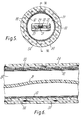
- the preferred optical cable shown in Figures 5 and 6 comprises a composite tube 50 which bounds a bore 51 and which comprises a longitudinally extending, transversely folded paper tape 52 whose longitudinally extending marginal edges overlap and are secured together by adhesive, a longitudinally extending, transversely folded plastics/aluminium/plastics composite tape 53 whose longitudinally extending marginal edges overlap at a position circumferentially spaced from the overlapping marginal edges of the paper tape 52, and an outer extruded sheath 54 of plastics material which is bonded to the outer plastics coating of the composite tape 53.
- Embedded in.the plastics sheath 54 at circumferentially spaced positions are twenty-four bunches 55 of compacted yarns of glass fibre, each of which has undulations which serve to improve the mechanical bonding of the bunch within the sheath and the flexibility of the cable.
- Loosely housed in the bore 51 of the optical cable is an undulating optical fibre element 21 as shown in Figure 3.
- the bore 51 has a diameter of 9mm; the composite tube 50 has an overall diameter of l5mm.
- Manufacture of the optical fibre element and manufacture of the optical cable of which the optical fibre element is a component part may be effected as separate operations, or manufacture of the optical fibre element and of the optical cable may be effected in tandem.
Landscapes
- Physics & Mathematics (AREA)
- General Physics & Mathematics (AREA)
- Optics & Photonics (AREA)
- Optical Fibers, Optical Fiber Cores, And Optical Fiber Bundles (AREA)
- Light Guides In General And Applications Therefor (AREA)
- Endoscopes (AREA)
- Insulated Conductors (AREA)
Applications Claiming Priority (2)
| Application Number | Priority Date | Filing Date | Title |
|---|---|---|---|
| GB848406635A GB8406635D0 (en) | 1984-03-14 | 1984-03-14 | Optical fibre element |
| GB8406635 | 1984-03-14 |
Publications (3)
| Publication Number | Publication Date |
|---|---|
| EP0157516A2 true EP0157516A2 (de) | 1985-10-09 |
| EP0157516A3 EP0157516A3 (en) | 1987-11-25 |
| EP0157516B1 EP0157516B1 (de) | 1992-09-09 |
Family
ID=10558068
Family Applications (1)
| Application Number | Title | Priority Date | Filing Date |
|---|---|---|---|
| EP85301746A Expired - Lifetime EP0157516B1 (de) | 1984-03-14 | 1985-03-13 | Fiberoptisches Bauteil |
Country Status (14)
| Country | Link |
|---|---|
| US (1) | US4690499A (de) |
| EP (1) | EP0157516B1 (de) |
| JP (1) | JPS60212714A (de) |
| KR (1) | KR900007559B1 (de) |
| AU (1) | AU565198B2 (de) |
| CA (1) | CA1254419A (de) |
| DE (1) | DE3586605T2 (de) |
| ES (2) | ES8609741A1 (de) |
| GB (2) | GB8406635D0 (de) |
| HK (1) | HK89588A (de) |
| IN (1) | IN163398B (de) |
| MY (1) | MY102429A (de) |
| NZ (1) | NZ211430A (de) |
| SG (1) | SG44288G (de) |
Cited By (3)
| Publication number | Priority date | Publication date | Assignee | Title |
|---|---|---|---|---|
| EP0236090A3 (de) * | 1986-02-28 | 1989-04-26 | BICC Public Limited Company | Optisches Kabel |
| WO1991000536A1 (de) | 1989-06-28 | 1991-01-10 | Siemens Aktiengesellschaft | Optisches kabel mit mindestens einer lichtwellenleiterader |
| EP0883007A1 (de) * | 1997-06-05 | 1998-12-09 | Alcatel | Kabel mit dichter Rohre und mindestens einem optischen Leiter |
Families Citing this family (19)
| Publication number | Priority date | Publication date | Assignee | Title |
|---|---|---|---|---|
| GB8432123D0 (en) * | 1984-12-19 | 1985-01-30 | Telephone Cables Ltd | Optical cables |
| GB8526107D0 (en) * | 1985-10-23 | 1985-11-27 | Telephone Cables Ltd | Optical fibre cable |
| GB8605018D0 (en) * | 1986-02-28 | 1986-04-09 | Bicc Plc | Optical fibre element |
| GB8619308D0 (en) * | 1986-08-07 | 1986-09-17 | Telephone Cables Ltd | Optical cables |
| JPH01126616A (ja) * | 1987-11-11 | 1989-05-18 | Olympus Optical Co Ltd | 内視鏡における光学繊維束の組付け方法 |
| GB8902552D0 (en) * | 1989-02-06 | 1989-03-22 | Telephone Cables Ltd | Optical fibre cable core for submarine use |
| US5039195A (en) * | 1990-05-29 | 1991-08-13 | At&T Bell Laboratories | Composite cable including portions having controlled flexural rigidities |
| US5247599A (en) * | 1992-06-05 | 1993-09-21 | Sumitomo Electric Fiber Optics Corp. | Steam resistant optical fiber cable |
| US5323480A (en) * | 1992-11-25 | 1994-06-21 | Raychem Corporation | Fiber optic splice closure |
| US5345526A (en) * | 1993-02-11 | 1994-09-06 | Comm/Scope | Fiber optic cable having buffer tubes with optical fiber bundles therein and method for making same |
| US5542020A (en) * | 1994-06-10 | 1996-07-30 | Commscope, Inc. | Fiber optic cable having extended contraction window and associated method and apparatus for fabricating the cable |
| US5604352A (en) * | 1995-04-25 | 1997-02-18 | Raychem Corporation | Apparatus comprising voltage multiplication components |
| US6052502A (en) * | 1997-09-22 | 2000-04-18 | Siecor Corporation | Ribbon optical cable having improved strength |
| US6253012B1 (en) | 1998-11-12 | 2001-06-26 | Alcatel | Cycled fiber lock for cross-functional totally dry optical fiber loose tube cable |
| DE10140310A1 (de) * | 2001-08-16 | 2003-02-27 | Ccs Technology Inc | Laschband |
| US20040076387A1 (en) * | 2002-10-17 | 2004-04-22 | Alcatel | Fiber optic tube and method of forming a fiber optic tube from a tape |
| KR100642382B1 (ko) * | 2003-02-26 | 2006-11-03 | 엘에스전선 주식회사 | 파형의 금속관을 구비하는 광케이블과 그 제조 방법 및 장치 |
| BRPI0707034A2 (pt) | 2006-08-30 | 2011-04-12 | Afl Telecommunications Llc | metódo de manufaturamento de um cabo, cabo, cabo furo-abaixo de tubo-duplo e cabo furo-abaixo de múltiplos tubos |
| US20170284614A1 (en) * | 2016-03-30 | 2017-10-05 | Kuo-Wei Pan | Decorative light wire |
Family Cites Families (21)
| Publication number | Priority date | Publication date | Assignee | Title |
|---|---|---|---|---|
| DE1629307A1 (de) * | 1966-10-18 | 1971-01-21 | Hugo Brendel | Vorrichtung zum Herstellen von mindestens teilweise aus Kunststoff bestchenden bahnfoermigen Gegenstaenden |
| US4089585A (en) * | 1974-12-18 | 1978-05-16 | Bicc Limited | Optical guides |
| AU498247B2 (en) * | 1974-12-27 | 1979-02-22 | Itt Industries Inc | Fire optic cable |
| US4028081A (en) * | 1975-12-11 | 1977-06-07 | Bell Telephone Laboratories, Incorporated | Method for manufacturing helical optical fiber |
| DK138564B (da) * | 1976-11-09 | 1978-09-25 | Nordiske Kabel Traad | Fremgangsmåde ved fremstilling af et lysledende element til anbringelse i et rørformet hylster. |
| GB1582851A (en) * | 1977-01-26 | 1981-01-14 | Bicc Ltd | Optical cables |
| CA1112310A (en) * | 1977-05-13 | 1981-11-10 | Peter Fearns | Overhead electric transmission systems |
| DE2743260C2 (de) * | 1977-09-26 | 1990-05-31 | kabelmetal electro GmbH, 3000 Hannover | Nachrichtenkabel mit Lichtwellenleitern und Verfahren zu seiner Herstellung |
| US4199225A (en) * | 1978-04-07 | 1980-04-22 | Bicc Limited | Optical guides |
| GB2019601A (en) * | 1978-04-20 | 1979-10-31 | Telephone Cables Ltd | Optical fibre cables |
| GB1584249A (en) * | 1978-05-12 | 1981-02-11 | Bicc Ltd | Optical cables |
| GB2085188B (en) * | 1980-09-26 | 1984-05-23 | Bicc Ltd | An improved optical cable |
| JPS57157206A (en) * | 1981-03-25 | 1982-09-28 | Nippon Telegr & Teleph Corp <Ntt> | Optical cable |
| CA1176091A (en) * | 1981-06-17 | 1984-10-16 | Charles D. Knipe | Optical cable |
| FR2509480A1 (fr) * | 1981-07-07 | 1983-01-14 | Lyonnaise Transmiss Optiques | Cable a fibres optiques pouvant supporter de grands allongements |
| JPS5833203A (ja) * | 1981-07-17 | 1983-02-26 | Furukawa Electric Co Ltd:The | 光通信線材 |
| JPS58150906A (ja) * | 1982-03-03 | 1983-09-07 | Nippon Telegr & Teleph Corp <Ntt> | テ−プ光フアイバ心線ユニツト |
| JPS5922006A (ja) * | 1982-07-28 | 1984-02-04 | Nippon Telegr & Teleph Corp <Ntt> | 光フアイバケ−ブルの製造方法 |
| DE3246594A1 (de) * | 1982-12-16 | 1984-06-20 | Hegler, Wilhelm, 8730 Bad Kissingen | Huellwellrohr |
| ZA844474B (en) * | 1983-06-17 | 1985-02-27 | Bicc Plc | Optical fibre ribbon structure |
| GB8316494D0 (en) * | 1983-06-17 | 1983-07-20 | Bicc Plc | Flexible elongate body |
-
1984
- 1984-03-14 GB GB848406635A patent/GB8406635D0/en active Pending
-
1985
- 1985-03-08 IN IN193/DEL/85A patent/IN163398B/en unknown
- 1985-03-11 CA CA000476165A patent/CA1254419A/en not_active Expired
- 1985-03-13 EP EP85301746A patent/EP0157516B1/de not_active Expired - Lifetime
- 1985-03-13 GB GB08506468A patent/GB2156094B/en not_active Expired
- 1985-03-13 US US06/711,247 patent/US4690499A/en not_active Expired - Fee Related
- 1985-03-13 NZ NZ211430A patent/NZ211430A/en unknown
- 1985-03-13 DE DE8585301746T patent/DE3586605T2/de not_active Expired - Fee Related
- 1985-03-13 ES ES541227A patent/ES8609741A1/es not_active Expired
- 1985-03-14 KR KR1019850001650A patent/KR900007559B1/ko not_active Expired
- 1985-03-14 AU AU39861/85A patent/AU565198B2/en not_active Ceased
- 1985-03-14 JP JP60049485A patent/JPS60212714A/ja active Pending
-
1986
- 1986-04-28 ES ES554448A patent/ES8707346A1/es not_active Expired
-
1987
- 1987-03-14 MY MYPI87000296A patent/MY102429A/en unknown
-
1988
- 1988-07-06 SG SG442/88A patent/SG44288G/en unknown
- 1988-11-03 HK HK895/88A patent/HK89588A/xx unknown
Cited By (5)
| Publication number | Priority date | Publication date | Assignee | Title |
|---|---|---|---|---|
| EP0236090A3 (de) * | 1986-02-28 | 1989-04-26 | BICC Public Limited Company | Optisches Kabel |
| WO1991000536A1 (de) | 1989-06-28 | 1991-01-10 | Siemens Aktiengesellschaft | Optisches kabel mit mindestens einer lichtwellenleiterader |
| EP0883007A1 (de) * | 1997-06-05 | 1998-12-09 | Alcatel | Kabel mit dichter Rohre und mindestens einem optischen Leiter |
| FR2764395A1 (fr) * | 1997-06-05 | 1998-12-11 | Alsthom Cge Alcatel | Cable a tube etanche comprenant au moins un conducteur optique |
| US6151434A (en) * | 1997-06-05 | 2000-11-21 | Alcatel | Sealed tube cable containing at least one optical conductor |
Also Published As
| Publication number | Publication date |
|---|---|
| GB2156094A (en) | 1985-10-02 |
| MY102429A (en) | 1992-06-30 |
| IN163398B (de) | 1988-09-17 |
| ES8609741A1 (es) | 1986-09-01 |
| CA1254419A (en) | 1989-05-23 |
| AU565198B2 (en) | 1987-09-10 |
| ES8707346A1 (es) | 1987-07-16 |
| AU3986185A (en) | 1985-09-19 |
| KR900007559B1 (ko) | 1990-10-15 |
| EP0157516A3 (en) | 1987-11-25 |
| HK89588A (en) | 1988-11-11 |
| GB8406635D0 (en) | 1984-04-18 |
| GB2156094B (en) | 1987-07-29 |
| DE3586605D1 (de) | 1992-10-15 |
| GB8506468D0 (en) | 1985-04-17 |
| SG44288G (en) | 1989-01-27 |
| US4690499A (en) | 1987-09-01 |
| EP0157516B1 (de) | 1992-09-09 |
| JPS60212714A (ja) | 1985-10-25 |
| ES554448A0 (es) | 1987-07-16 |
| ES541227A0 (es) | 1986-09-01 |
| NZ211430A (en) | 1988-01-08 |
| DE3586605T2 (de) | 1993-02-25 |
| KR850006609A (ko) | 1985-10-14 |
Similar Documents
| Publication | Publication Date | Title |
|---|---|---|
| US4690499A (en) | Optical fibre element housed in a tube resiliently set in a form such that its longitudinal axis follows a path greater than the rectilinear distance between points to be connected | |
| US4630887A (en) | Optical fibre ribbon structure | |
| US4699461A (en) | Overhead flexible electric conductor | |
| EP0129438B1 (de) | Flexibler elektrischer Freileiter | |
| US4878732A (en) | Optical communication cable with ribbon waveguide support | |
| US4679897A (en) | Optical fibre element for use in an optical cable | |
| US6704481B2 (en) | Cable assembly having ripcords with excess length and ripcords attached to tape | |
| US4676591A (en) | Optical fibre ribbon structure | |
| GB2187305A (en) | An optical fibre in undulating tube having line of weakness | |
| GB1583383A (en) | Optical cables | |
| EP0092980A2 (de) | Flexibler gestreckter Körper | |
| CN85105411A (zh) | 一种改进的光导纤维带结构 | |
| GB2170921A (en) | Optical cables | |
| CN1004944B (zh) | 改进的光纤器件 | |
| EP1416305A2 (de) | Rohr für optische Fasern und Methode zur Herstellung dieses Rohrs aus einem Klebeband | |
| TH3493A (th) | องค์ประกอบโครงสร้างสายเคเบิลขึงเหนือศรีษะ?สำหรับการส่งจ่ายกำลังไฟฟ้าและแสง | |
| GB2183060A (en) | Optical fibre cable | |
| TH3139B (th) | องค์ประกอบโครงสร้างสายเคเบิลขึงเหนือศรีษะ?สำหรับการส่งจ่ายกำลังไฟฟ้าและแสง |
Legal Events
| Date | Code | Title | Description |
|---|---|---|---|
| PUAI | Public reference made under article 153(3) epc to a published international application that has entered the european phase |
Free format text: ORIGINAL CODE: 0009012 |
|
| AK | Designated contracting states |
Kind code of ref document: A2 Designated state(s): DE FR IT NL SE Designated state(s): DE FR IT NL SE |
|
| 17P | Request for examination filed |
Effective date: 19860211 |
|
| PUAL | Search report despatched |
Free format text: ORIGINAL CODE: 0009013 |
|
| AK | Designated contracting states |
Kind code of ref document: A3 Designated state(s): DE FR IT NL SE |
|
| 17Q | First examination report despatched |
Effective date: 19900710 |
|
| GRAA | (expected) grant |
Free format text: ORIGINAL CODE: 0009210 |
|
| AK | Designated contracting states |
Kind code of ref document: B1 Designated state(s): DE FR IT NL SE |
|
| RIN1 | Information on inventor provided before grant (corrected) |
Inventor name: KEENE, IAN WILLIAM Inventor name: TAYLOR, JOHN EDWARD |
|
| ET | Fr: translation filed | ||
| REF | Corresponds to: |
Ref document number: 3586605 Country of ref document: DE Date of ref document: 19921015 |
|
| ITF | It: translation for a ep patent filed | ||
| PGFP | Annual fee paid to national office [announced via postgrant information from national office to epo] |
Ref country code: FR Payment date: 19930211 Year of fee payment: 9 |
|
| PGFP | Annual fee paid to national office [announced via postgrant information from national office to epo] |
Ref country code: SE Payment date: 19930219 Year of fee payment: 9 |
|
| PGFP | Annual fee paid to national office [announced via postgrant information from national office to epo] |
Ref country code: DE Payment date: 19930222 Year of fee payment: 9 |
|
| ITTA | It: last paid annual fee | ||
| PGFP | Annual fee paid to national office [announced via postgrant information from national office to epo] |
Ref country code: NL Payment date: 19930331 Year of fee payment: 9 |
|
| PLBE | No opposition filed within time limit |
Free format text: ORIGINAL CODE: 0009261 |
|
| STAA | Information on the status of an ep patent application or granted ep patent |
Free format text: STATUS: NO OPPOSITION FILED WITHIN TIME LIMIT |
|
| 26N | No opposition filed | ||
| PG25 | Lapsed in a contracting state [announced via postgrant information from national office to epo] |
Ref country code: SE Free format text: LAPSE BECAUSE OF NON-PAYMENT OF DUE FEES Effective date: 19940314 |
|
| PG25 | Lapsed in a contracting state [announced via postgrant information from national office to epo] |
Ref country code: NL Effective date: 19941001 |
|
| NLV4 | Nl: lapsed or anulled due to non-payment of the annual fee | ||
| PG25 | Lapsed in a contracting state [announced via postgrant information from national office to epo] |
Ref country code: FR Effective date: 19941130 |
|
| PG25 | Lapsed in a contracting state [announced via postgrant information from national office to epo] |
Ref country code: DE Effective date: 19941201 |
|
| REG | Reference to a national code |
Ref country code: FR Ref legal event code: ST |
|
| EUG | Se: european patent has lapsed |
Ref document number: 85301746.5 Effective date: 19941010 |