EP0156984B1 - Haarbehandlungsapparat - Google Patents
Haarbehandlungsapparat Download PDFInfo
- Publication number
- EP0156984B1 EP0156984B1 EP84115290A EP84115290A EP0156984B1 EP 0156984 B1 EP0156984 B1 EP 0156984B1 EP 84115290 A EP84115290 A EP 84115290A EP 84115290 A EP84115290 A EP 84115290A EP 0156984 B1 EP0156984 B1 EP 0156984B1
- Authority
- EP
- European Patent Office
- Prior art keywords
- head
- person
- hair
- framework
- blower
- Prior art date
- Legal status (The legal status is an assumption and is not a legal conclusion. Google has not performed a legal analysis and makes no representation as to the accuracy of the status listed.)
- Revoked
Links
Images


Classifications
-
- A—HUMAN NECESSITIES
- A45—HAND OR TRAVELLING ARTICLES
- A45D—HAIRDRESSING OR SHAVING EQUIPMENT; EQUIPMENT FOR COSMETICS OR COSMETIC TREATMENTS, e.g. FOR MANICURING OR PEDICURING
- A45D20/00—Hair drying devices; Accessories therefor
- A45D20/04—Hot-air producers
- A45D20/08—Hot-air producers heated electrically
- A45D20/14—Portable drying stands
-
- A—HUMAN NECESSITIES
- A45—HAND OR TRAVELLING ARTICLES
- A45D—HAIRDRESSING OR SHAVING EQUIPMENT; EQUIPMENT FOR COSMETICS OR COSMETIC TREATMENTS, e.g. FOR MANICURING OR PEDICURING
- A45D20/00—Hair drying devices; Accessories therefor
- A45D20/22—Helmets with hot air supply or ventilating means, e.g. electrically heated air current
- A45D20/24—Shape or structure of the helmet body
- A45D2020/245—Shape or structure of the helmet body of open configuration, e.g. with several movable heat sources
Definitions
- This invention relates to hair heat processing apparatus, and more particularly to hair heat processing apparatus of the infrared ray type.
- Hair promoting apparatus otherwise sometimes referred to as hair heat processing apparatus, are utilized today to heat and dry a person's hair. Such heating and drying is usually required during or after the hair has been processed such as perming, or while it is being worked such as drying, or for drying after washing, or for similar treatments.
- Some hair promoting or heat processing apparatus utilize infrared rays for heating and drying the hair.
- Conventionally available infrared hair promoting devices often incorporate an infrared radiator in the form of an elongated pipe of silica glass that is energized to generate heat and radiates far infrared rays to heat and dry hair.
- These devices are often formed so that the heat radiating member (in the elongated pipe for radiating far infrared rays), and a reflecting mirror, of the apparatus for reflecting infrared rays radiated from the heat radiating member, are formed to have a circular configuration. By doing so the distance between same and the hair to be processed may be made uniform at the center and opposite ends of the infrared ray radiator.
- a hair promoting apparatus which comprises framework means, mounting means for said framework means, adjustment means selectively operable to adjust the position of said framework means, infrared radiating means carried by said framework means for disposition relative to the head of a person, including infrared radiators of linear configuration, and control means connected to said infrared radiating means to control the operation thereof.
- This type of apparatus lacks any means for blowing air against the rear of the head so that the drying process is of limited effectivity.
- US-A-42 42 810 discloses a hair styling apparatus with a cross frame member, support member, a control power section associated with the cross frame member, cross arm members with flexible conduit means for carrying electrical appliances, namely hot air conveying means, such as diffusors, blow driers and lamps.
- hot air conveying means such as diffusors, blow driers and lamps.
- Another object of this invention is to provide an infrared radiating hair promoting apparatus, which utilizes infrared radiating members, which are of linear construction and configuration thus permitting some head movement while disposed therebetween, and wherein a number of radiating units are each accommodated in independent cases of common structure and the units are, in turn, connected to each other by connecting conducts thus reducing the cost of dies, moles and the like.
- This invention is characterised by the combination of blower means mounted on said framework means for blowing air towards the head of a person for circulating air in the region of the person's head, said blower means including an air blower and a motor for driving said blower, and another infrared radiating means connected to said framework means, which radiating means faces the rear of the person's head and is adapted to be cooled by means of said blower means.
- said infrared radiating means includes a heat radiating member, a reflecting mirror having a parabola cross-section to contain said reflecting mirror therein, and a wire cage attached to said reflecting mirror.
- the heat radiating member according to this invention has a linear configuration, and a radiator unit which reflects infrared rays radiated from the heat radiating member also has a linear configuration. Accordingly, when compared with a conventional hair promoting apparatus which includes a radiator unit having a circular configuration extending around a head of a person, according to the hair promoting apparatus, the distance from the head to the heat radiating member or to the radiator unit is seldom varied extremely even if the position of the head varies.
- radiator units provided for a head front top portion and a head rear top portion are contained in independent cases and connected to a framework by means of pipes, a sufficient spacing can be provided for the head of a person. Accordingly, removal of steam and circulation of air can be assured sufficiently promoting drying of a hair, and since the head can be thus observed well, the positioning of the head can be advantageously attained easily.
- a hair promoting apparatus incorporating the instant invention and which includes a framework mounted in top of a main post 5 which is, in turn, mounted to and received by a main pipe 3.
- Pipe 3, and post 5 extend vertically up from the center of a base including a plurality of legs 2 each having a caster 1 mounted at an end thereof.
- An adjustment nut 4, provided on top of pipe 3, when loosened permits post 6 to slide within pipe 3 and to be rotated therewithin to adjust the height of framework 6 and the positioning thereof. When nut 4 is tightened post 5 is prevented from movement within pipe 3.
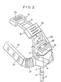
- FIGs. 1 and 2 show framework 6 disposed upon a movable base it should be understood that framework 6 and, the apparatus associated therewith, may just as easily be securely suspended from a ceiling or securely mounted on a wall.
- Appropriate and conventional mounting structure would be utilized to so mount framework 6 in a thus relatively fixed position.
- conventional means would be provided for such a mounting to permit height and rotational adjustment of framework 6 and its associated apparatus.
- Framework 6 has accommodated therein an air blower 7 (Fig. 3) a motor 8 for rotating blower 7, and a blast pipe 11 which is opened to louvers 10 (Figs. 1 and 3) of a front cover 9 mounted on the front of framework 6.
- Front cover 9 (Fig. 2) has a window hole 13 (Fig. 3) perforated therein in which a radiator unit 12 (Figs. 1 and 3) is accommodated such that the direction thereof can be adjusted upwardly and downwardly within an angle of about 10 degrees by operation of a semicircularly protruding knob 14.
- Front cover 9 further has a blasting louver 15 provided therein which allows an air flow to pass therethrough to cool radiator unit 12.
- a pair of pipes 16 extend erectlyfrom the top of front cover 9.
- a head rear top case 18, in which a radiator unit 17 is accommodated is mounted at upper ends of the pipes 16.
- Another pair of pipes 19 extend erectly from the head rear top case 18.
- a head front top case 21, in which a further radiator unit 20 is accommodated is mounted at upper ends of the pipes 19.
- a pair of connecting members 22 having a rectangular cross section are mounted on opposite left and right sides of framework 6.
- a side case 24 is mounted for rotation on an end of each of the connecting members 22 such that the direction of a further radiator 23 (Fig. 1) mounted on each connecting member 22 and directed downwardly at an angle of 10 degrees, can be changed further downwardly by an angle of 20 degrees from this position.
- Each of the radiator units 12, 17, 20 and 23 includes a heat radiating member 25 (Fig. 3) having a linear silica glass pipe and a heating wire which is contained in the pipe and is energizable to generate heat in order that infrared rays or far infrared rays may be radiated from the silica glass pipe.
- a reflecting mirror 26, having a cross section approximated to a parabola for reflecting infrared rays or far infrared rays radiated from radiating members 25 is carried by units 12, 17, 20 and 23.
- Awire gauze 27 (Figs. 3 and 4) for protecting heat radiating member 25 and reflecting mirror 26, and for preventing soiling of reflecting mirror 26 and possible burning of the skin of a person from an inadvertent touch with the heat radiating member 25, is appropriately positioned on units 12, 17, 20 and 23.
- a movable arm 35 (Figs. 1 and 3), having a temperature sensor 34 (Fig. 3) mounted at one end thereof, is mounted at its other or a base end for pivotal motion on front cover 9.
- the mounting of arm 35 is such that it can be moved from a position adjacent front cover 9 to a position extending therefrom and in which temperature sensor 34 is located on an extension of a center line of front cover 9.
- a further indicator member 36 (Figs. 1,2 and 4) is provided at the top of front cover 9 and has a bulb contained therein which is energized simultaneously with energization of heat radiating members 25 to radiate light and indicate that heat radiating members 25 are now generating heat. Consequently, the person can be prevented from touching and being burnt by, heat radiating members 25 without recognizing that heat radiating members 25 are generating heat.
- Framework 6 has a hinge portion 6a (Fig. 3) protruding from one of the side faces thereof.
- a control unit 30 is mounted at a side portion thereof for pivotal motion on hinge portion 6a of the framework 6.
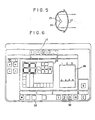
- Control unit 30 has a number of controlling switches 28 (Figs. 2, 4 and 6) thereon and contains a control circuit 29 (Fig. 3) which is responsive to operation of switches 28 for controlling duration of electric current flowing through heat radiating members 25, and so on.
- control unit 30 can be positioned to a position above an upper face of framework 6 to allow switches 28 thereon to be operated from behind the hair promoting apparatus, or unit 30 can be pivoted sidewardly of framework 6 to allow switches 28 to be operated from the front side of the hair promoting apparatus. Accordingly, operations for controlling the hair promoting apparatus are possible from various positions around framework 6 depending upon the position of the hair promoting apparatus relative to a floor and a wall or walls.
- An electrical conductor 31 extends from control circuit 29 through pipes 16 and 19 and connects radiation units 17 and 20 to control circuit 29. Conductor 31 also extends through connecting pipes 22 and connects radiator units 23 to control circuit 29. Accordingly, the electric conductor 31 cannot be observed from outside, thus preventing deterioration of the appearance of the hair promoting apparatus.
- the hair promoting apparatus which has such a construction as described above is actually used, it is moved in an arbitrary position by means of the casters 1 and legs 2.
- Nut 4 is loosened to adjust the hair promoting apparatus relative to the height of the head of a person whereafter it is tightened to fix the apparatus in the thus adjusted position.
- the head of the person is observed: from between framework 6 and head rear top case 18; between head rear top case 18 and head front top case 21; from between pipes 16 and pipes 19; and from above and below side cases 24.
- the persons head may then be set in position so that it may be illuminated uniformly over the hair thereof by infrared rays from radiator units 12, 17, 20 and 23.
- the directions of radiator unit 12 and 17 for the head rear portion and radiator units 23 for the head side portions are adjusted upwardly or downwardly depending upon the length of the hair at such positions.
- switches 28, as shown in Fig. 6, are selectively operated depending upon the permanent set, drying of the hair washed, kind of a mode of dyeing of the hair, intensity of cold liquid used, conditions of the hair such as thickness, degree of damage, water absorbing power, and so on.
- Such operation of switches 28 can be recognized from lighting of indicating lamp 32 on the indicator panel.
- heat radiating members 25 are energized to radiate infrared rays which are directed towards the hair to heat and dry the hair.
- the duration of such energization of heat radiating members 25 is controlled in accordance with an established program which is determined in response to operations of switches 28.
- motor 8 is energized to operate air blower 7 so that blasts of air are blown out from louvers 10 against the hair to promote drying of the same.
- circuit 29 operates to interrupt the electric current to heat radiating members 25 thereby preventing damage to the hair due to overheating.
- a rise of temperature in the interior of framework 6, head rear top case 18, head front top case 21 and side cases 24 is inhibited due to the fact that air is circulated through blasting louvers 15 and 33 perforated in those components. Thus, they can be prevented from overheating.
- radiator units 12 and 23 may be directed downwardly; while on the contrary where the person has short hair, they may be directed upwardly; so that infrared rays may be illuminated uniformly on the entire hair irrespective of the length of the hair.
- side cases 24 are each arranged such that radiator units 23 thereon are inclined to have the front end thereof located upwardly, the heat radiating members 25 thereof are positioned to extend along a border of the hair. Accordingly, infrared rays illuminated on a face of a person are reduced in quantity when compared with a hair promoting apparatus of the horizontally installed type, thereby reducing a disagreeable feeling of the person arising from the fact that the face is heated, the eyes become fatigued by infrared rays, and so on.
- a heat radiating member has a linear configuration
- a radiator unit which reflects infrared rays radiated from the heat radiating member also has a linear configuration. Accordingly, when compared with a conventional hair promoting apparatus which includes a radiator unit having a circular configuration extending around a head of a person, according to the hair promoting apparatus, the distance from the head to the heat radiating member or to the radiator unit is seldom varied extremely even if the position of the head varies.
- radiator units provided for a head front top portion and a head rear top portion are contained in independent cases and connected to a framework by means of pipes, a sufficient spacing can be provided for the head of a person. Accordingly, removal of steam and circulation of air can be assured sufficiently promoting drying of a hair, and since the head can be thus observed well, the positioning of the head can be advantageously attained easily.
Landscapes
- Radiation-Therapy Devices (AREA)
- Cleaning And Drying Hair (AREA)
Claims (2)
Priority Applications (1)
| Application Number | Priority Date | Filing Date | Title |
|---|---|---|---|
| AT84115290T ATE52171T1 (de) | 1983-12-16 | 1984-12-12 | Haarbehandlungsapparat. |
Applications Claiming Priority (4)
| Application Number | Priority Date | Filing Date | Title |
|---|---|---|---|
| JP19285783U JPS60101003U (ja) | 1983-12-16 | 1983-12-16 | 毛髪促進装置 |
| JP192857/83U | 1983-12-16 | ||
| US63108484A | 1984-07-16 | 1984-07-16 | |
| US631084 | 1984-07-16 |
Publications (3)
| Publication Number | Publication Date |
|---|---|
| EP0156984A2 EP0156984A2 (de) | 1985-10-09 |
| EP0156984A3 EP0156984A3 (en) | 1986-08-27 |
| EP0156984B1 true EP0156984B1 (de) | 1990-04-25 |
Family
ID=26507559
Family Applications (1)
| Application Number | Title | Priority Date | Filing Date |
|---|---|---|---|
| EP84115290A Revoked EP0156984B1 (de) | 1983-12-16 | 1984-12-12 | Haarbehandlungsapparat |
Country Status (3)
| Country | Link |
|---|---|
| US (1) | US4914273A (de) |
| EP (1) | EP0156984B1 (de) |
| DE (1) | DE3482024D1 (de) |
Cited By (1)
| Publication number | Priority date | Publication date | Assignee | Title |
|---|---|---|---|---|
| US7479618B2 (en) | 2005-02-28 | 2009-01-20 | The Procter & Gamble Company | Device for heat treatment |
Families Citing this family (29)
| Publication number | Priority date | Publication date | Assignee | Title |
|---|---|---|---|---|
| JPH0728770B2 (ja) * | 1987-11-24 | 1995-04-05 | タカラベルモント株式会社 | 毛髪処理促進装置 |
| ATE109629T1 (de) * | 1988-12-06 | 1994-08-15 | Olymp Karl Herzog Gmbh & Co | Kopftrockenhaube. |
| FR2644045B1 (fr) * | 1989-03-09 | 1991-08-23 | Fre Gis Srl | Appareil automatique pour le sechage des cheveux |
| US5050232A (en) * | 1990-03-28 | 1991-09-17 | Bgk Finishing Systems, Inc. | Movable heat treating apparatus utilizing proportionally controlled infrared lamps |
| US5279048A (en) * | 1991-08-23 | 1994-01-18 | Intelligent Designs, Inc. | Hands free hair dryer and hair dryer accessory |
| FR2689735B1 (fr) * | 1992-04-13 | 1995-01-27 | Krups Robert Gmbh Co Kg | Appareil de soufflage d'air chaud pour sécher les cheveux. |
| EP0679350B1 (de) * | 1994-04-27 | 2002-08-07 | Koninklijke Philips Electronics N.V. | Haartrockner mit geregeltem Luftstrom |
| US6116250A (en) * | 1996-07-20 | 2000-09-12 | Wella Aktiengesellschaft | Process of permanent hair shaping |
| US6038786A (en) * | 1998-04-16 | 2000-03-21 | Excel Dryer Inc. | Hand dryer |
| KR200195568Y1 (ko) * | 1998-06-26 | 2000-09-01 | 김대성 | 할로겐 헤어드라이기 |
| US7039301B1 (en) | 1999-10-04 | 2006-05-02 | Excel Dryer, Inc. | Method and apparatus for hand drying |
| US6606800B2 (en) * | 2000-01-22 | 2003-08-19 | Wella Ag | Electric hair treatment appliance |
| KR100783442B1 (ko) * | 2000-09-08 | 2007-12-07 | 다카라 벨몬트 가부시키가이샤 | 모발처리촉진장치 |
| JP4456254B2 (ja) * | 2000-10-20 | 2010-04-28 | 株式会社大廣製作所 | 頭髪処理促進機 |
| JP4435398B2 (ja) * | 2000-10-25 | 2010-03-17 | 株式会社大廣製作所 | 頭髪処理促進機 |
| JP4295440B2 (ja) * | 2001-01-09 | 2009-07-15 | 株式会社三龍社 | 同心逆回転減速機を有する頭髪加熱機 |
| KR20030083461A (ko) * | 2002-04-23 | 2003-10-30 | 송웅부 | 헤어 드라이 장치 |
| MX2007010259A (es) | 2005-02-23 | 2007-09-11 | Procter & Gamble | Dispositivo para el tratamiento del cabello por medio de calor. |
| JP2009504178A (ja) * | 2005-08-17 | 2009-02-05 | ワイ.ケー.ホールディングス リミティド | シラミ駆除システムと方法 |
| GB2444028A (en) * | 2006-11-23 | 2008-05-28 | Stephen Ball | Personal drying apparatus with heater, fan and infra-red source |
| WO2008099408A2 (en) * | 2007-02-16 | 2008-08-21 | Y.K. Holdings Ltd. | Lice extermination system and method |
| US8434238B2 (en) * | 2007-06-29 | 2013-05-07 | Andis Company | Hair dryer with light source |
| US8693855B2 (en) * | 2009-05-07 | 2014-04-08 | Cambridge Engineering, Inc | Infra-red heater assembly |
| ES2795355T3 (es) * | 2009-07-10 | 2020-11-23 | Braun Gmbh | Proceso automatizado para el cuidado del cabello |
| USD669222S1 (en) * | 2011-05-23 | 2012-10-16 | Dyson Limited | Part of a hand dryer |
| CN103799667A (zh) * | 2014-02-21 | 2014-05-21 | 苏州智信通电子科技有限公司 | 多功能卷发机 |
| US10820677B2 (en) * | 2015-06-05 | 2020-11-03 | Sherron M Thomas | Cordless hair dryer with ionizing solution |
| AU2017213447A1 (en) * | 2016-08-11 | 2018-03-01 | Pacific Trends International Pty Ltd | Heater and a control system for a heater |
| USD843552S1 (en) * | 2017-05-02 | 2019-03-19 | P.S. Pibbs, Inc. | Four-headed heating lamp assembly with adjustable arms |
Family Cites Families (20)
| Publication number | Priority date | Publication date | Assignee | Title |
|---|---|---|---|---|
| US1787251A (en) * | 1928-10-03 | 1930-12-30 | Eastern Lab Inc | Hair drying and treating apparatus |
| FR898979A (fr) * | 1943-06-23 | 1945-05-14 | Nouveau procédé de séchage des cheveux et appareils s'y rapportant | |
| FR995503A (fr) * | 1945-03-14 | 1951-12-04 | Perfectionnements apportés aux dispositifs pour le séchage des cheveux | |
| US2500872A (en) * | 1946-04-10 | 1950-03-14 | Root Frank Keniston | Paint baking apparatus |
| GB611663A (en) * | 1946-05-03 | 1948-11-02 | Patrick Francis Aloysius Grein | Improvements in and connected with hair waving |
| FR932187A (fr) * | 1946-08-12 | 1948-03-15 | Dispositif de séchage des cheveux | |
| FR944623A (fr) * | 1947-04-02 | 1949-04-11 | Modèle perfectionné de séchoir pour cheveux à rayons infra-rouges | |
| GB773514A (en) * | 1954-10-20 | 1957-04-24 | Raymond Bessone | Hair heater for permanent waving processes |
| FR1158364A (fr) * | 1956-10-12 | 1958-06-13 | Appareil électrique combiné de chauffage et d'éclairage | |
| FR1261383A (fr) * | 1960-04-07 | 1961-05-19 | Casque chauffant pour soins capillaires | |
| US3867948A (en) * | 1971-05-03 | 1975-02-25 | Adolf Kallenborn | Infra red radiation means with fan means |
| FR2314638A7 (fr) * | 1975-06-10 | 1977-01-07 | Velecta | Dispositif pour le sechage des cheveux |
| CH604606A5 (en) * | 1975-12-03 | 1978-09-15 | Herbert Kubat | Adjustable infrared lamp for hair treatment |
| JPS5827921B2 (ja) * | 1976-12-27 | 1983-06-13 | シャープ株式会社 | 加温式パ−マネント装置 |
| JPS5920161Y2 (ja) * | 1977-04-30 | 1984-06-12 | シャープ株式会社 | 加温式パ−マネント装置の温度感知センサ |
| JPS54136963A (en) * | 1978-04-14 | 1979-10-24 | Sharp Corp | Hot permanent waver |
| JPS6031602Y2 (ja) * | 1978-04-14 | 1985-09-21 | シャープ株式会社 | 加温式パ−マネント装置 |
| US4242810A (en) * | 1979-05-24 | 1981-01-06 | Blanco David M | Hair styling apparatus |
| US4265029A (en) * | 1979-12-04 | 1981-05-05 | Jenkins Kenneth A | Motor vehicle dryer stand |
| DE3133851A1 (de) * | 1981-08-27 | 1983-03-24 | Wella Ag | Waermebehandlungsgeraet fuer kopfhaare |
-
1984
- 1984-12-12 EP EP84115290A patent/EP0156984B1/de not_active Revoked
- 1984-12-12 DE DE8484115290T patent/DE3482024D1/de not_active Expired - Fee Related
-
1987
- 1987-05-26 US US07/056,262 patent/US4914273A/en not_active Expired - Fee Related
Cited By (1)
| Publication number | Priority date | Publication date | Assignee | Title |
|---|---|---|---|---|
| US7479618B2 (en) | 2005-02-28 | 2009-01-20 | The Procter & Gamble Company | Device for heat treatment |
Also Published As
| Publication number | Publication date |
|---|---|
| EP0156984A3 (en) | 1986-08-27 |
| EP0156984A2 (de) | 1985-10-09 |
| DE3482024D1 (de) | 1990-05-31 |
| US4914273A (en) | 1990-04-03 |
Similar Documents
| Publication | Publication Date | Title |
|---|---|---|
| EP0156984B1 (de) | Haarbehandlungsapparat | |
| EP0317902B1 (de) | Haarbehandlungsgerät | |
| US4918290A (en) | Portable towel heating device | |
| US5437001A (en) | Upright radiant electric heating appliance | |
| US2422450A (en) | Combined space heater and grill | |
| US2852657A (en) | Heater | |
| JPH05321883A (ja) | 扇風機 | |
| JPH0713670Y2 (ja) | 換気扇 | |
| JPH06103100B2 (ja) | 熱風循環式調理器 | |
| JPS6060453A (ja) | 温風器 | |
| JPH0233684Y2 (de) | ||
| JPH0996489A (ja) | 暖房乾燥装置 | |
| JPS6096204A (ja) | 毛髪促進装置 | |
| CN219083242U (zh) | 一种复合加热器 | |
| JPH0233683Y2 (de) | ||
| CN115949989A (zh) | 一种复合加热器 | |
| JPS6130122Y2 (de) | ||
| JPS6458968A (en) | Air conditioner | |
| CA1209631A (en) | Combined radiant and fan heater | |
| US2694971A (en) | Air circulator | |
| KR200262619Y1 (ko) | 전기온풍기 | |
| JP2851833B2 (ja) | 赤外線治療装置 | |
| JP2002333153A (ja) | 浴室用乾燥暖房装置 | |
| JPH10246511A (ja) | 暖房装置 | |
| JPH10118201A (ja) | 遠赤外線照射装置 |
Legal Events
| Date | Code | Title | Description |
|---|---|---|---|
| PUAI | Public reference made under article 153(3) epc to a published international application that has entered the european phase |
Free format text: ORIGINAL CODE: 0009012 |
|
| AK | Designated contracting states |
Kind code of ref document: A2 Designated state(s): AT BE CH DE FR GB IT LI LU NL SE |
|
| PUAL | Search report despatched |
Free format text: ORIGINAL CODE: 0009013 |
|
| AK | Designated contracting states |
Kind code of ref document: A3 Designated state(s): AT BE CH DE FR GB IT LI LU NL SE |
|
| 17P | Request for examination filed |
Effective date: 19870226 |
|
| 17Q | First examination report despatched |
Effective date: 19870715 |
|
| GRAA | (expected) grant |
Free format text: ORIGINAL CODE: 0009210 |
|
| RAP3 | Party data changed (applicant data changed or rights of an application transferred) |
Owner name: TAKARA COMPANY, INC. |
|
| AK | Designated contracting states |
Kind code of ref document: B1 Designated state(s): AT BE CH DE FR GB IT LI LU NL SE |
|
| PG25 | Lapsed in a contracting state [announced via postgrant information from national office to epo] |
Ref country code: SE Effective date: 19900425 Ref country code: NL Effective date: 19900425 Ref country code: IT Free format text: LAPSE BECAUSE OF FAILURE TO SUBMIT A TRANSLATION OF THE DESCRIPTION OR TO PAY THE FEE WITHIN THE PRESCRIBED TIME-LIMIT;WARNING: LAPSES OF ITALIAN PATENTS WITH EFFECTIVE DATE BEFORE 2007 MAY HAVE OCCURRED AT ANY TIME BEFORE 2007. THE CORRECT EFFECTIVE DATE MAY BE DIFFERENT FROM THE ONE RECORDED. Effective date: 19900425 Ref country code: FR Effective date: 19900425 Ref country code: BE Effective date: 19900425 Ref country code: AT Effective date: 19900425 |
|
| REF | Corresponds to: |
Ref document number: 52171 Country of ref document: AT Date of ref document: 19900515 Kind code of ref document: T |
|
| REF | Corresponds to: |
Ref document number: 3482024 Country of ref document: DE Date of ref document: 19900531 |
|
| EN | Fr: translation not filed | ||
| NLV1 | Nl: lapsed or annulled due to failure to fulfill the requirements of art. 29p and 29m of the patents act | ||
| PG25 | Lapsed in a contracting state [announced via postgrant information from national office to epo] |
Ref country code: GB Effective date: 19901212 |
|
| PG25 | Lapsed in a contracting state [announced via postgrant information from national office to epo] |
Ref country code: LU Free format text: LAPSE BECAUSE OF NON-PAYMENT OF DUE FEES Effective date: 19901231 Ref country code: LI Free format text: LAPSE BECAUSE OF NON-PAYMENT OF DUE FEES Effective date: 19901231 Ref country code: CH Free format text: LAPSE BECAUSE OF NON-PAYMENT OF DUE FEES Effective date: 19901231 |
|
| PLBI | Opposition filed |
Free format text: ORIGINAL CODE: 0009260 |
|
| 26 | Opposition filed |
Opponent name: WELLA AG Effective date: 19901218 |
|
| GBPC | Gb: european patent ceased through non-payment of renewal fee | ||
| REG | Reference to a national code |
Ref country code: CH Ref legal event code: PL |
|
| PG25 | Lapsed in a contracting state [announced via postgrant information from national office to epo] |
Ref country code: DE Effective date: 19910903 |
|
| RDAG | Patent revoked |
Free format text: ORIGINAL CODE: 0009271 |
|
| STAA | Information on the status of an ep patent application or granted ep patent |
Free format text: STATUS: PATENT REVOKED |
|
| 27W | Patent revoked |
Effective date: 19911114 |