EP0155397A2 - Durchführung für eine Leitung, wie Kabel, Rohr oder dergl., durch eine Wandöffnung - Google Patents
Durchführung für eine Leitung, wie Kabel, Rohr oder dergl., durch eine Wandöffnung Download PDFInfo
- Publication number
- EP0155397A2 EP0155397A2 EP84115817A EP84115817A EP0155397A2 EP 0155397 A2 EP0155397 A2 EP 0155397A2 EP 84115817 A EP84115817 A EP 84115817A EP 84115817 A EP84115817 A EP 84115817A EP 0155397 A2 EP0155397 A2 EP 0155397A2
- Authority
- EP
- European Patent Office
- Prior art keywords
- press ring
- ring
- wall
- fitting
- annular groove
- Prior art date
- Legal status (The legal status is an assumption and is not a legal conclusion. Google has not performed a legal analysis and makes no representation as to the accuracy of the status listed.)
- Granted
Links
Images

Classifications
-
- F—MECHANICAL ENGINEERING; LIGHTING; HEATING; WEAPONS; BLASTING
- F16—ENGINEERING ELEMENTS AND UNITS; GENERAL MEASURES FOR PRODUCING AND MAINTAINING EFFECTIVE FUNCTIONING OF MACHINES OR INSTALLATIONS; THERMAL INSULATION IN GENERAL
- F16L—PIPES; JOINTS OR FITTINGS FOR PIPES; SUPPORTS FOR PIPES, CABLES OR PROTECTIVE TUBING; MEANS FOR THERMAL INSULATION IN GENERAL
- F16L5/00—Devices for use where pipes, cables or protective tubing pass through walls or partitions
- F16L5/02—Sealing
- F16L5/10—Sealing by using sealing rings or sleeves only
-
- F—MECHANICAL ENGINEERING; LIGHTING; HEATING; WEAPONS; BLASTING
- F16—ENGINEERING ELEMENTS AND UNITS; GENERAL MEASURES FOR PRODUCING AND MAINTAINING EFFECTIVE FUNCTIONING OF MACHINES OR INSTALLATIONS; THERMAL INSULATION IN GENERAL
- F16B—DEVICES FOR FASTENING OR SECURING CONSTRUCTIONAL ELEMENTS OR MACHINE PARTS TOGETHER, e.g. NAILS, BOLTS, CIRCLIPS, CLAMPS, CLIPS OR WEDGES; JOINTS OR JOINTING
- F16B9/00—Connections of rods or tubular parts to flat surfaces at an angle
- F16B9/05—Connections of rods or tubular parts to flat surfaces at an angle by way of an intermediate member
- F16B9/054—Connections of rods or tubular parts to flat surfaces at an angle by way of an intermediate member the intermediate member being threaded
-
- F—MECHANICAL ENGINEERING; LIGHTING; HEATING; WEAPONS; BLASTING
- F16—ENGINEERING ELEMENTS AND UNITS; GENERAL MEASURES FOR PRODUCING AND MAINTAINING EFFECTIVE FUNCTIONING OF MACHINES OR INSTALLATIONS; THERMAL INSULATION IN GENERAL
- F16B—DEVICES FOR FASTENING OR SECURING CONSTRUCTIONAL ELEMENTS OR MACHINE PARTS TOGETHER, e.g. NAILS, BOLTS, CIRCLIPS, CLAMPS, CLIPS OR WEDGES; JOINTS OR JOINTING
- F16B9/00—Connections of rods or tubular parts to flat surfaces at an angle
- F16B9/05—Connections of rods or tubular parts to flat surfaces at an angle by way of an intermediate member
- F16B9/056—Connections of rods or tubular parts to flat surfaces at an angle by way of an intermediate member the intermediate member extending through the flat surface; the rod or tubular part extending through the flat surface
-
- F—MECHANICAL ENGINEERING; LIGHTING; HEATING; WEAPONS; BLASTING
- F16—ENGINEERING ELEMENTS AND UNITS; GENERAL MEASURES FOR PRODUCING AND MAINTAINING EFFECTIVE FUNCTIONING OF MACHINES OR INSTALLATIONS; THERMAL INSULATION IN GENERAL
- F16B—DEVICES FOR FASTENING OR SECURING CONSTRUCTIONAL ELEMENTS OR MACHINE PARTS TOGETHER, e.g. NAILS, BOLTS, CIRCLIPS, CLAMPS, CLIPS OR WEDGES; JOINTS OR JOINTING
- F16B2200/00—Constructional details of connections not covered for in other groups of this subclass
- F16B2200/40—Clamping arrangements where clamping parts are received in recesses of elements to be connected
- F16B2200/403—Threaded clamping parts
-
- Y—GENERAL TAGGING OF NEW TECHNOLOGICAL DEVELOPMENTS; GENERAL TAGGING OF CROSS-SECTIONAL TECHNOLOGIES SPANNING OVER SEVERAL SECTIONS OF THE IPC; TECHNICAL SUBJECTS COVERED BY FORMER USPC CROSS-REFERENCE ART COLLECTIONS [XRACs] AND DIGESTS
- Y10—TECHNICAL SUBJECTS COVERED BY FORMER USPC
- Y10S—TECHNICAL SUBJECTS COVERED BY FORMER USPC CROSS-REFERENCE ART COLLECTIONS [XRACs] AND DIGESTS
- Y10S285/00—Pipe joints or couplings
- Y10S285/921—Snap-fit
Definitions
- the invention relates to an implementation for a line, such as cable, pipe or the like.
- a line such as cable, pipe or the like.
- the fitting Through a wall opening, consisting of an elastic fitting, which seals on the one hand against the line, on the other hand against the soffit of the wall opening to be filled in by the fitting, and from which the fitting in the wall opening elastically pressing device, the fitting has a circular groove surrounding the line, open to the outside of the wall, and the pressing device is formed by a press ring which can be pressed axially into the groove, the wall thickness of which is greater than the width of the undeformed groove in the unstressed fitting.
- the wedge-shaped increase in the wall thickness of the press ring extends over its entire axial length which engages in the annular groove, which, in the case of axially long adapters, results in a large wall thickness of the press ring at the thick end of its wedge profile and the correspondingly large radial structural dimensions of the bushing overall.
- the sealing of the fitting against the line is carried out with the aid of a sealing sleeve, which is formed in one piece on the fitting and must be thermally shrunk onto the line, which requires its own complex operation when assembling the bushing.
- the invention has for its object to provide a implementation of the type mentioned so that with the help of the press ring a seal of the fitting is also possible against the line, and that the press ring retains small radial wall thickness even with axially long dimensions and still over its whole A good compression of the fitting against the line and reveal is guaranteed everywhere along the length.
- the press ring is divided over its entire axial length into ring segments with a central angle of at most 180 0 , and that the ring segments are detachably connected to one another by tangential to the ring circumference and pin receptacles.
- the compression ring also has a balancing action between the radially outward and inward compression forces on the adapter, so that it is pressed and sealed evenly against the line on the one hand and against the reveal on the other. Therefore, there is no need for tapering the outer and / or inner circumferential surface of the press ring over its entire axial length for the compression of the fitting; these surfaces can be essentially cylindrical if only the wall thickness of the press ring is greater than the width of the undeformed annular groove in the untensioned fitting.
- An axially long press ring can also be formed with a uniformly small wall thickness and still result in a good compression of the fitting everywhere.
- a further preferred embodiment is characterized in that the press ring on the outer and / or inner surface of its wall engaging in the annular groove has a circumferential groove which forms a thread with which the press ring can be screwed into the fitting, and that the grooving is only on the front wall part, which increases in wall thickness, while the cylindrical wall part is thread-free, and that the press ring rests with an annular shoulder on the outside of the forehead of the fitting.
- the line 1 for example a cable with an internal structure (not shown in detail), is led through the opening 2 of a concrete wall 3.
- the implementation comprises an elastic fitting 4 made of rubber or similar elastically deformable material, which seals on the one hand against the line 1, on the other hand against the reveal 5 of the wall opening 2 to be filled by the fitting 4. 6 with a fixed in the wall 3 front plate is designated, which can form part of the reveal 5 with its inner peripheral surface 6.1.
- a pressure device is provided which elastically compresses the fitting 4 in the wall opening 2 and is formed by a press ring 7 which has a groove in the form of a thread 9.
- the fitting 4 has a circular groove 8 surrounding the duct 1, open to the outside of the wall, which extends in the axial direction over the length of the area in which the fitting 4 is intended to seal against the duct 1 or the soffit 5.
- the press ring 7 is axially screwed the press ring 7, the wall thickness of which is greater than the width of the undeformed ring groove 8 in the still untensioned fitting 4.
- the press ring therefore causes material displacement in the fitting 4 when screwing into the ring groove 8, with the result that the fitting 4 line 1, on the one hand, and soffit 5, on the other, apply pressure accordingly.
- the wall thickness of the press ring 7 increases, seen in axial section according to FIG.
- the cylindrical wall part 7.3 extends up to an annular shoulder 7.4 at the end of the press ring 7 protruding from the annular groove 8, this end being designed as a collar 10 with end holes 11 arranged around the periphery for the attachment of a suitable key and for receiving the key serve appropriately provided key pin.
- Press ring 7 in the fitting 4 allows.
- the last course of the thread 9 is located in the transition between the front wall part 7.2, which increases in wedge shape in the wall thickness, and the adjoining cylindrical wall part 7.3.
- a corresponding nut thread in the annular groove 8 is not required since the threads of the thread 9 are positively pressed into the elastic material of the fitting 4.
- the annular groove 8 is in the undeformed and unclamped fitting 4 essentially, that is again down to a small draft angle of about 1 0 , cylindrical, thus has a substantially cylindrical inner surface and cylindrical outer surface, the groove width between the two surfaces being smaller than the wall thickness of the cylindrical Wall part 7.3 of the press ring 7 is.
- the press ring 7 is divided over its entire length into two ring segments 7a, 7b with a central angle of 180 0th
- the two ring segments 7a, 7b are detachably connected by pins 12.1 directed tangentially to the ring circumference and associated pin receptacles 12.2.
- the smallest inner diameter of the press ring 7, that is to say when the ring segments 7a, 7b are completely plugged together, is still somewhat smaller than the diameter of the inner circumferential surface of the annular groove 8, so that the press ring also compresses the fitting piece 4 radially inwards by compressing the ring segments 7a, 7b can exercise.
- the press ring 7 can of course also be divided into more than two ring segments, for example in three ring segments each with 120 °, four ring segments each with 90 °, six ring segments each with 60 ° etc. In any case, achieved that the press ring 7 in diameter change radially and thereby the fitting 4 can be pressed anywhere and both inwards and outwards evenly.
- the divided press ring 7 has the advantage that the ring segments can be joined from the side on the intermediate line and the line does not have to be pulled through the press ring, which would be essential for one-piece press rings.
Landscapes
- Engineering & Computer Science (AREA)
- General Engineering & Computer Science (AREA)
- Mechanical Engineering (AREA)
- Laying Of Electric Cables Or Lines Outside (AREA)
- Gasket Seals (AREA)
- Details Of Indoor Wiring (AREA)
- Installation Of Indoor Wiring (AREA)
- Flexible Shafts (AREA)
Abstract
Description
- Die Erfindung betrifft eine Durchführung für eine Leitung, wie Kabel, Rohr oder dergl. durch eine Wandöffnung, bestehend aus einem elastischen Paßstück, das einerseits gegen die Leitung, andererseits gegen die Laibung der vom Paßstück, auszufüllenden Wandöffnung abdichtet, und aus einer das Paßstück in der Wandöffnung elastisch verpressenden Druckvorrichtung, wobei das Paßstück eine die Leitung kreisförmig umgebende, zur Wandaußenseite hin offene Ringnut aufweist, und die Druckvorrichtung von einem axial in die Ringnut eindrückbaren Preßring gebildet ist, dessen Wandstärke größer als die Breite der unverformten Ringnut im unverspannten Paßstück ist.
- Bei einer aus der US-PS 3 548 079 bekannten Durchführung dieser Art vergrößert sich die Wandstärke des Preßringes, im Axialschnitt gesehen, keilförmig vom in Einsteckrichtung vorderen Ende aus, wozu die äußere Umfangsfläche des Preßringes entsprechend konisch ausgebildet ist. Außerdem ist an der äußeren oder inneren Umfangsfläche des Preßringes ein Gewinde vorgesehen, das in ein Gegengewinde an der gegenüber liegenden Umfangsfläche der Ringnut greift. Der mit Hilfe dieser Gewinde in die Ringnut eingeschraubte Preßring weitet die Ringnut auf und verpreßt dadurch das Paßstück gegen die Laibung der Wandöffnung. Dabei erstreckt sich die keilförmige Vergrößerung der Wandstärke des Preßringes über dessen gesamte in die Ringnut greifende axiale Länge, was bei axial langen Paßstücken eine große Wandstärke des Preßringes am dicken Ende seines Keilprofils und dem entsprechend große radiale Bauabmessungen der Durchführung insgesamt ergibt. Die Abdichtung des Paßstücks gegenüber der Leitung erfolgt mit Hilfe einer Dichtmanschette, die einstückig am Paßstück ausgebildet ist und auf die Leitung thermisch aufgeschrumpft werden muß, was einen eigenen aufwendigen Arbeitsgang bei der Montage der Durchführung erfordert.
- Der Erfindung liegt die Aufgabe zugrunde, eine Durchführung der eingangs genannten Art so auszubilden, daß mit Hilfe des Preßringes eine Abdichtung des Paßstückes auch gegenüber der Leitung möglich ist, und daß der Preßring auch bei axial langen Abmessungen geringe radiale Wandstärke behält und trotzdem über seine ganze Länge hinweg überall eine gute Verpressung des Paßstückes gegen Leitung und Laibung gewährleistet.
- Diese Aufgabe wird nach der Erfindung dadurch gelöst, daß der Preßring über seine gesamte axiale Länge in Ringsegmente mit einem Zentriwinkel von höchstens 1800 geteilt ist, und daß die Ringsegmente durch tangential zum -Ringumfang- gerichtete Zapfen und Zapfenaufnahmen lösbar miteinander verbunden sind.
- Durch die erfindungsgemäße Teilung des Preßringes wird erreicht, daß sich die Ringsegmente in Richtung der sie jeweils verbindenden Zapfen und Zapfenaufnahmen gegeneinander verstellen können und also der Preßring im Ganzen bezüglich seines Durchmessers gleichsam "atmen" kann. Der Preßring vermag daher seine Druckwirkung radial sowohl nach außen als auch nach innen auf das Paßstück zu entfalten und dieses somit gegen die Leitung wie gegen die Laibung zu verpressen, wozu lediglich Voraussetzung ist, daß der kleinstmögliche Innendurchmesser des Preßringes kleiner als der Innendurchmesser der unverformten Ringnut im unverspannten Paßstück ist. Im Rahmen dieser dem Preßring durch seine Teilung ermöglichten Durchmesseranpassung wirkt der Preßring auch ausgleichend zwischen den radial auswärts und einwärts gerichteten Preßkräften auf das Paßstück, so daß dieses gleichmäßig gegen die Leitung einerseits und gegen die Laibung andererseits verpreßt und abgedichtet wird. Daher bedarf es für die Verpressung des Paßstückes keiner Konizität der äußeren und/oder inneren Umfangsfläche des Preßringes über dessen gesamte axiale Länge; diese Flächen können im wesentlichen zylindrisch sein, wenn nur die Wandstärke des Preßringes größer als die Breite der unverformten Ringnut im unverspannten Paßstück ist. Auch ein axial langer Preßring kann also mit gleichmäßig geringer Wandstärke ausgebildet und dennoch eine überall gute Verpressung des Paßstückes ergeben. Das Maß dieser Verpressung richtet sich im wesentlichen nur nach dem Verhältnis der Wandstärke des Preßringes einerseits und der demgegenüber kleineren Breite der Ringnut im noch unverformten und unverspannten Zustand des Paßstücks andererseits, so daß durch Wahl dieses Verhältnisses die Verpressung des Paßstückes in der Wandöffnung nach Wunsch eingestellt werden kann.
- Eine bevorzugte Ausführungsform der Erfindung ist im Ergebnis dadurch gekennzeichnet, daß sich die Wandstärke des Preßringes, im Axialschnitt gesehen, vom in Einsteckrichtung vorderen Ende aus keilförmig vergrößert und diese keilförmige Vergrößerung der Wanddicke nur auf einen vorderen Teil der in die Ringnut greifenden Preßringwand beschränkt ist, an den sich durchmessergleich ein im wesentlichen zylindrischer Wandteil anschließt, und daß die Ringnut im unverformten und unverspannten Paßstück im wesentlichen zylindrische Innen- und Außenflächen aufweist, wobei die Nutbreite kleiner als die Wanddicke des zylindrischen Wandteiles des Preßringes ist.
- Eine weiter bevorzugte Ausführungsform ist dadurch gekennzeichnet, daß der Preßring an der Außen- und/ oder Innenfläche seiner in die Ringnut greifenden Wand eine in Umfangsrichtung verlaufende Rillierung aufweist, die ein Gewinde bildet, mit dem der Preßring in das Paßstück einschraubbar ist, und daß sich die Rillierung nur am sich in der Wanddicke vergrössernden vorderen Wandteil befindet, während der zylindrische Wandteil gewindefrei ist, und daß der Preßring außen mit einer Ringschulter der Stirn des Paßstückes anliegt. Durch die Beschränkung des Gewindes nur auf den vorderen, sich in der Wanddicke erweiternden Teil des Preßringes wird erreicht, daß das Paßstück zwischen diesem Teil und der Ringschulter des Preßringes axial zusammen gestaucht wird,-wenn der in seiner gesamten axialen Länge in die Ringnut eingetretene und sich mit der Ringschulter gegen das Paßstück angelegte Preßring noch tiefer in die Ringnut vorgeschraubt wird. Diese axiale Stauchung des Paßstückes ergibt eine zusätzliche radiale Vergrößerung des Paßstückquerschnitts und dadurch eine weitere Verbesserung der Dichtwirkung des Paßstückes gegenüber der Leitung und der Laibung der Wandöffnung. Es genügt, die Rillierung nur am Preßring vorzusehen. Der Preßring kann sich dann das zum Vorschrauben erforderliche Gegengewinde im Paßstück durch entsprechende elastische Verformung desselben gleichsam selbsttätig schaffen. Im zylindrischen Teil ist dann eine durch keinerleit Rillierung gestörte dichte Flächenanlage zwischen Preßring und Paßstück möglich.
- Es empfiehlt sich, die das Gewinde bildende Rillierung bis zum Beginn des zylindrischen Wandteiles verlaufen zu lassen, so daß der letzte Gewindegang im Übergang zwischen dem sich in der Wanddicke keilförmig vergrößernden vorderen Wandteil und dem sich daran anschließenden zylindrischen Wandteil liegt.
- Im folgenden wird die Erfindung an einem in der Zeich nung dargestellten Ausführungsbeispiel näher erläu- tert; es zeigen:
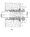
- Fig. 1 einen Axialschnitt durch eine Wanddurchführung nach der Erfindung,
- Fig. 2 einen Axialschnitt durch den Preßring nach Fig. 1 in einer im Vergleich zu Fig. 1 vergrößerten Darstellung,
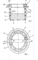
- Fig. 3 eine Stirnansicht des Preßringes nach Fig. 1 in teilweise auseinander gezogenem Zustand der beiden Preßringteile,
- Fig. 4 einen Axialschnitt durch das Paßstück der Wanddurchführung nach Fig. 1 in ebenfalls vergrößerter Darstellung und in noch unverformten und unverspanntem Zustand.
- In der Zeichnungist die Leitung 1, beispielsweise ein Kabel mit im einzelnen nicht dargestelltem Innenaufbau, durch die Öffnung 2 einer Betonwand 3 hindurchgeführt. Die Durchführung umfaßt ein elastisches Paßstück 4 aus Gummi oder ähnlich elastisch verformbarem Werkstoff, das einerseits gegen die Leitung 1, andererseits gegen die Laibung 5 der vom Paßstück 4 auszufüllenden Wandöffnung 2 abdichtet. Mit 6 ist eine fest in die Wand 3 eingelassene Stirnplatte bezeichnet, die mit ihrer inneren Umfangsfläche 6.1 einen Teil der Laibung 5 bilden kann. Außerdem ist eine das Paßstück 4 in der Wandöffnung 2 elastisch verpressende Druckvorrichtung vorgesehen, die von einem Preßring 7 gebildet ist, der eine Rillierung in Form eines Gewindes 9 trägt. Im einzelnen besitzt das Paßstück 4 eine die Leitung 1 kreisförmig umgebende, zur Wandaußenseite hin offene Ringnut 8, die in axialer Richtung über die Länge desjenigen Bereiches reicht, in der das Paßstück 4 gegenüber der Leitung 1 bzw. der Laibung 5 abdichten soll. In diese Ringnut 8 ist axial der Preßring 7 eingeschraubt, dessen Wandstärke größer ist als die Breite der unverformten Ringnut 8 im noch unverspannten Paßstück 4. Der Preßring bewirkt daher beim Einschrauben in die Ringnut 8 eine Werkstoffverdrängung im Paßstück 4 mit dem Ergebnis, daß sich das Paßstück 4 der Leitung 1 einerseits und der Laibung 5 andererseits mit entsprechendem Druck anlegt. Die Wanddicke des Preßrings 7 vergrößert sich, gesehen im Axialschnitt entsprechend Fig. 2, von dem in Einsteckrichtung vorderen Ringende 7.1 aus keilförmig längs eines vorderen Teils 7.2 der in die Ringnut 8 greifenden Preßringwand. Im Ausführungsbeispiel ist der Fall einer keilförmigen Erweiterung sowohl der inneren als auch der äußeren Ringfläche dargestellt, so daß das Axialprofil der Wand nach Art eines Doppelkeiles ausgebildet ist. An diesen vorderen, sich erweiternden Wandteil 7.2 schließt sich durchmessergleich ein im wesentlichen zylindrischer Wandteil 7.3 an, der lediglich eine sehr geringe Schräge von nur etwa 1° besitzt, um bei der Herstellung die Entformung des Preßringes aus der Spritzgußform zu erleichtern. Der zylindrische Wandteil 7.3 reicht bis zu einer Ringschulter 7.4 an dem aus der Ringnut 8 vorstehenden Ende des Preßringes 7, wobei dieses Ende als Bund 10 mit zum Ansatz eines geeigneten Schlüssels über den Umfang verteilt angeordneten Stirnlöchern 11 ausgebildet ist, die zur Aufnahme von am Schlüssel in geeigneter Weise vorgesehenen Schlüsselzapfen dienen. An der Außen- und der Innenfläche nur des sich keilförmig erweiternden vorderen Wandteils 7.2 befindet sich das Gewinde 9, welches das Einschrauben des
- Preßrings 7 in das Paßstück 4 ermöglicht. Der letzte Gang des Gewindes 9 befindet sich im Übergang zwischen dem sich in der Wanddicke keilförmig vergrössernden vorderen Wandteil 7.2 und dem sich daran anschließenden zylindrischen Wandteil 7.3. Eines entsprechenden Muttergewindes in der Ringnut 8 bedarf es nicht, da sich die Gänge des Gewindes 9 formschlüssig in den elastischen Werkstoff des Paßstücks 4 eindrücken. Die Ringnut 8 ist im unverformten und unverspannten Paßstück 4 im wesentlichen, d. h. wiederum bis auf eine geringe Entformungsschräge von etwa 10 , zylindrisch, besitzt also eine im wesentlichen zylindrische Innenfläche und zylindrische Außenfläche, wobei die Nutbreite zwischen beiden Flächen kleiner als die Wanddicke des zylindrischen Wandteils 7.3 des Preßrings 7 ist. Der Preßring 7 ist über seine gesamte Länge in zwei Ringsegmente 7a, 7b mit einem Zentriwinkel von 1800 geteilt. Die beiden Ringsegmente 7a, 7b sind durch tangential zum Ringumfang gerichtete Zapfen 12.1 und zugeordnete Zapfenaufnahmen 12.2 lösbar verbunden. Der kleinste Innendurchmesser des Preßrings 7, also bei vollständig zusammengesteckten Ringsegmenten 7a, 7b ist noch etwas kleiner als der Durchmesser der inneren Umfangsfläche der Ringnut 8, so daß der Preßring durch Zusammendrücken der Ringsegmente 7a, 7b auch einen Druck auf das Paßstück 4 radial nach innen ausüben kann. Statt in nur zwei Ringsegmente 7a, 7a kann der Preßring 7 selbstverständlich auch in mehr als zwei Ringsegmente geteilt werden, beispielsweise in drei Ringsegmente mit je 120°, vier Ringsegmente mit je 90°, sechs Ringsegmente mit je 60° usw. In jedem Fall wird erreicht, daß sich der Preßring 7 im Durchmesser radial verändern und dadurch das Paßstück 4 überall und sowohl nach innen als auch nach außen gleichmäßig verpressen kann. Im übrigen bietet der geteilte Preßring 7 den Vorteil, daß die Ringsegmente von der Seite her an der dazwischen liegenden Leitung zusammengefügt werden können und die Leitung nicht durch den Preßring hindurchgezogen werden muß, was bei einstückigen Preßringen unerläßlich wäre.
Claims (5)
Priority Applications (1)
| Application Number | Priority Date | Filing Date | Title |
|---|---|---|---|
| AT84115817T ATE32779T1 (de) | 1984-03-06 | 1984-12-19 | Durchfuehrung fuer eine leitung, wie kabel, rohr oder dergl., durch eine wandoeffnung. |
Applications Claiming Priority (4)
| Application Number | Priority Date | Filing Date | Title |
|---|---|---|---|
| DE3408122 | 1984-03-06 | ||
| DE3408122 | 1984-03-06 | ||
| DE3431805 | 1984-08-30 | ||
| DE3431805 | 1984-08-30 |
Publications (3)
| Publication Number | Publication Date |
|---|---|
| EP0155397A2 true EP0155397A2 (de) | 1985-09-25 |
| EP0155397A3 EP0155397A3 (en) | 1986-06-25 |
| EP0155397B1 EP0155397B1 (de) | 1988-03-02 |
Family
ID=25819091
Family Applications (1)
| Application Number | Title | Priority Date | Filing Date |
|---|---|---|---|
| EP84115817A Expired EP0155397B1 (de) | 1984-03-06 | 1984-12-19 | Durchführung für eine Leitung, wie Kabel, Rohr oder dergl., durch eine Wandöffnung |
Country Status (7)
| Country | Link |
|---|---|
| US (1) | US4627647A (de) |
| EP (1) | EP0155397B1 (de) |
| CA (1) | CA1240659A (de) |
| DE (1) | DE3469584D1 (de) |
| DK (1) | DK156529C (de) |
| ES (1) | ES284126Y (de) |
| NO (1) | NO165002C (de) |
Cited By (7)
| Publication number | Priority date | Publication date | Assignee | Title |
|---|---|---|---|---|
| EP0246113A3 (de) * | 1986-05-15 | 1990-04-25 | Walter Rose GmbH & Co. KG | Vorrichtung, besonders zum Abdichten zwischen Durchführungswänden und Kabeln |
| FR2673263A1 (fr) * | 1991-02-26 | 1992-08-28 | Rubberia Sa | Ensemble formant joint pour raccordement souple entre deux elements. |
| AT397115B (de) * | 1992-03-23 | 1994-02-25 | Katzenberger Beton Fertigteil | Durchführung eines zu- oder ablaufrohres |
| FR2699292A1 (fr) * | 1992-12-15 | 1994-06-17 | France Telecom | Procédé de préparation par lentillage multiple d'une fibre optique en vue d'un couplage optimum avec un phototransducteur et système optique obtenu. |
| NL1008480C2 (nl) * | 1998-03-04 | 1999-09-07 | Filoform Bv | Inrichting en werkwijze voor het afdichten van een doorvoeropening. |
| DE202010011501U1 (de) * | 2010-08-17 | 2011-11-23 | Doyma Gmbh & Co | Dichtsystem, Dichtkörper sowie Klemmkörper für selbiges |
| CN105421596A (zh) * | 2015-10-28 | 2016-03-23 | 河南省第二建设集团有限公司 | 一种钢管与混凝土楼板预留孔之间的密封方法 |
Families Citing this family (27)
| Publication number | Priority date | Publication date | Assignee | Title |
|---|---|---|---|---|
| DE3525644C1 (de) * | 1985-07-18 | 1986-08-14 | Werner 7925 Dischingen Hauff | Anordnung zur Brandueberwachung in einem Gebaeude |
| US4832119A (en) * | 1986-06-05 | 1989-05-23 | Bloor Trevor J | Multi-tube heat exchanger and connectors therefor |
| FI85623C (fi) * | 1990-01-12 | 1992-05-11 | Rp Oy Teollisuuden Ja Rakentaj | Foerfarande foer kraginstallering och genomfoeringskrag. |
| US5263746A (en) * | 1992-03-04 | 1993-11-23 | Cornwall Kenneth R | Adjustably mounted fitting assembly |
| US5711536A (en) * | 1994-05-11 | 1998-01-27 | Tuf-Tite, Inc. | Seal component for use in on-site poured concrete or plastic tank or box components of fluid distribution systems |
| JP2950154B2 (ja) * | 1994-06-17 | 1999-09-20 | 住友電装株式会社 | ワイヤハーネス用グロメット |
| US5603457A (en) * | 1994-09-16 | 1997-02-18 | Sidmore; Philip W. | Transfer panel nozzle |
| DE19542650A1 (de) * | 1995-11-15 | 1997-05-22 | Bosch Gmbh Robert | Temperaturfeste Kabeldurchführung und Verfahren zu deren Herstellung |
| US5741030A (en) * | 1996-12-31 | 1998-04-21 | Moore; Michael A. | Air duct starting collar with quick mounting means |
| US5886297A (en) * | 1997-02-28 | 1999-03-23 | Vogt; William R. | Method and apparatus for sealing, on a non-permanent basis, a housing for enclosing electronic equipment |
| US6254143B1 (en) | 1999-04-21 | 2001-07-03 | Central States Industrial Equipment And Service, Inc. | Transfer panel assembly and method of construction |
| SE519409C2 (sv) * | 2000-12-21 | 2003-02-25 | Faluplast Ab | Röranslutningsdon |
| IL142868A (en) * | 2001-04-30 | 2006-10-31 | Pouma Ltd | Connection system |
| US20030025277A1 (en) * | 2001-07-31 | 2003-02-06 | Torres Robert W. | High Pressure seal |
| US6725611B2 (en) | 2001-09-13 | 2004-04-27 | Defiglio Steven Peter | Sleeve holder for utility conduit |
| US20040094951A1 (en) * | 2002-11-04 | 2004-05-20 | Sigrist Peter C. | Conduit sealing system |
| US20050218648A1 (en) * | 2003-08-01 | 2005-10-06 | Logue George Jr | Pipe or conduit collar |
| KR100709781B1 (ko) * | 2005-03-21 | 2007-04-23 | 김대현 | 슬래브 관통용 배관의 고정방법과 그 지지장치 |
| KR100676727B1 (ko) * | 2005-03-31 | 2007-02-01 | 한재광 | 배관파이프 고정장치 |
| US7338095B1 (en) | 2005-12-05 | 2008-03-04 | Dura-Tite Systems, Llc | Plastic heating duct connectors |
| USD558325S1 (en) | 2005-12-05 | 2007-12-25 | Dura-Tite Systems, Llc | Trunk line take-off |
| DE102006000184A1 (de) * | 2006-04-19 | 2007-10-25 | Hilti Ag | Leistungsdurchführung |
| US7645946B2 (en) * | 2006-05-15 | 2010-01-12 | Smith Jeffrey M | Two-piece pipe escutcheon |
| DE102012212832A1 (de) * | 2012-07-23 | 2014-01-23 | Hilti Aktiengesellschaft | Baugruppe für eine Leitungsdurchführung |
| US9130362B2 (en) * | 2012-12-20 | 2015-09-08 | Remy Technologies, L.L.C. | Connector member including a locking element |
| DE202015102252U1 (de) * | 2015-05-04 | 2015-07-22 | Funke Kunststoffe Gmbh | Muffenadapter |
| CZ309776B6 (cs) * | 2022-07-22 | 2023-09-27 | Škoda JS a.s | Hermetická potrubní průchodka |
Family Cites Families (10)
| Publication number | Priority date | Publication date | Assignee | Title |
|---|---|---|---|---|
| US1192927A (en) * | 1911-12-23 | 1916-08-01 | Babcock & Wilcox Co | Tube-joint for boilers, &c. |
| US1835155A (en) * | 1928-04-14 | 1931-12-08 | Victor H Harbert | Pipe clamp |
| US1788366A (en) * | 1929-09-03 | 1931-01-13 | Appleton Electric Co | Adjustable connecter |
| US2493556A (en) * | 1947-12-20 | 1950-01-03 | Standard Oil Dev Co | Supporting and sealing member |
| LU38571A1 (de) * | 1959-06-29 | |||
| US3498642A (en) * | 1967-11-06 | 1970-03-03 | Schurz Controls Corp | Pipe fitting |
| US3548079A (en) * | 1969-05-16 | 1970-12-15 | Raychem Corp | Bulkhead feedthrough |
| US3649034A (en) * | 1970-09-15 | 1972-03-14 | Thunderline Corp | Modular interwall seal unit |
| US3758066A (en) * | 1971-11-11 | 1973-09-11 | Harry W Skinner | Apparatus for fabricating a pipe joint sealing device |
| DE2317752A1 (de) * | 1973-04-09 | 1974-10-24 | Gervin Mueller | Wasserdichte, isolierende wanddurchfuehrung fuer elektrische kabel |
-
1984
- 1984-12-19 EP EP84115817A patent/EP0155397B1/de not_active Expired
- 1984-12-19 DE DE8484115817T patent/DE3469584D1/de not_active Expired
-
1985
- 1985-01-18 NO NO850239A patent/NO165002C/no unknown
- 1985-01-24 ES ES1985284126U patent/ES284126Y/es not_active Expired
- 1985-02-27 DK DK090385A patent/DK156529C/da not_active IP Right Cessation
- 1985-03-01 CA CA000475554A patent/CA1240659A/en not_active Expired
- 1985-03-04 US US06/707,877 patent/US4627647A/en not_active Expired - Fee Related
Cited By (8)
| Publication number | Priority date | Publication date | Assignee | Title |
|---|---|---|---|---|
| EP0246113A3 (de) * | 1986-05-15 | 1990-04-25 | Walter Rose GmbH & Co. KG | Vorrichtung, besonders zum Abdichten zwischen Durchführungswänden und Kabeln |
| FR2673263A1 (fr) * | 1991-02-26 | 1992-08-28 | Rubberia Sa | Ensemble formant joint pour raccordement souple entre deux elements. |
| AT397115B (de) * | 1992-03-23 | 1994-02-25 | Katzenberger Beton Fertigteil | Durchführung eines zu- oder ablaufrohres |
| FR2699292A1 (fr) * | 1992-12-15 | 1994-06-17 | France Telecom | Procédé de préparation par lentillage multiple d'une fibre optique en vue d'un couplage optimum avec un phototransducteur et système optique obtenu. |
| NL1008480C2 (nl) * | 1998-03-04 | 1999-09-07 | Filoform Bv | Inrichting en werkwijze voor het afdichten van een doorvoeropening. |
| EP0940615A1 (de) * | 1998-03-04 | 1999-09-08 | Filoform B.V. | Vorrichtung und Verfahren zum Dichten einer Durchlassöffnung |
| DE202010011501U1 (de) * | 2010-08-17 | 2011-11-23 | Doyma Gmbh & Co | Dichtsystem, Dichtkörper sowie Klemmkörper für selbiges |
| CN105421596A (zh) * | 2015-10-28 | 2016-03-23 | 河南省第二建设集团有限公司 | 一种钢管与混凝土楼板预留孔之间的密封方法 |
Also Published As
| Publication number | Publication date |
|---|---|
| US4627647A (en) | 1986-12-09 |
| EP0155397A3 (en) | 1986-06-25 |
| ES284126U (es) | 1985-06-01 |
| ES284126Y (es) | 1986-01-16 |
| NO165002B (no) | 1990-08-27 |
| DK90385A (da) | 1985-09-07 |
| DE3469584D1 (en) | 1988-04-07 |
| CA1240659A (en) | 1988-08-16 |
| DK156529B (da) | 1989-09-04 |
| NO850239L (no) | 1985-09-09 |
| NO165002C (no) | 1990-12-05 |
| DK156529C (da) | 1990-01-29 |
| EP0155397B1 (de) | 1988-03-02 |
| DK90385D0 (da) | 1985-02-27 |
Similar Documents
| Publication | Publication Date | Title |
|---|---|---|
| EP0155397B1 (de) | Durchführung für eine Leitung, wie Kabel, Rohr oder dergl., durch eine Wandöffnung | |
| DE2426234C2 (de) | Verbindungsstück aus Kunststoff oder Metall zum lösbaren Anschluß von Rohren mit unterschiedlichen Durchmessern | |
| DE3121899C2 (de) | ||
| DE2524845C3 (de) | Lichtleiterkupplung zur Kupplung zweier Lichtleiter | |
| DE19729876C2 (de) | Steckverbinder für Koaxialkabel | |
| DE69701379T2 (de) | Rohrverbindung | |
| DE69222509T2 (de) | Dichtende Schnellkupplungsvorrichtung für flexible, ungeflochtene Rohre aus Metall | |
| EP0005865A2 (de) | Steckbares Verbindungssystem für Druckleitungen, insbesondere Bremssystem-Leitungen | |
| DE19614073B4 (de) | Trennungssichere Rohrverbindung | |
| DE1963299C3 (de) | Anschluß für mindestens ein druckmittelbeaufschlagtes, ein glattes Ende aufweisendes rohrförmiges Element | |
| DE2731242C2 (de) | Verbindungsanordnung für zwei Rohre mit Blockierung bei Zugbeanspruchung | |
| DE2625460A1 (de) | Spaltring, insbesondere fuer eine schlauch- oder rohrkupplung | |
| DE3322809C2 (de) | Durchführung für Leitungen, wie Kabel, Rohre oder dergl., durch eine Wandöffnung | |
| DE2404555A1 (de) | Schnellkupplung fuer schlaeuche und starre rohre | |
| DE2201306A1 (de) | Rohrkupplung | |
| WO1984001902A1 (fr) | Raccord de catheter | |
| DE60204287T2 (de) | Kupplung zur verbindung eines rohrs oder schlauchs durch einschieben | |
| DE4212771A1 (de) | Rohrverschraubung | |
| DE2402892C2 (de) | Dichtungssystem für die stirnseitige Verbindung eines Rohres mit einem schraubenförmig gewellten Rohr | |
| DE1985039U (de) | Anschlussstueck fuer wellenleiter. | |
| DE60114302T2 (de) | Rohrkupplung | |
| DE4433640A1 (de) | Rohrschelle | |
| DE2309649A1 (de) | Kabelverschraubung | |
| DE8619671U1 (de) | Kupplung zum Anschließen eines medizinischen Schlauches, insbesondere eines Drains oder eines Katheters, an eine weitere Einrichtung | |
| DE3413792C1 (de) | Verbindung für miteinander verschraubbare Rohre |
Legal Events
| Date | Code | Title | Description |
|---|---|---|---|
| PUAI | Public reference made under article 153(3) epc to a published international application that has entered the european phase |
Free format text: ORIGINAL CODE: 0009012 |
|
| AK | Designated contracting states |
Designated state(s): AT BE CH DE FR GB IT LI NL SE |
|
| PUAL | Search report despatched |
Free format text: ORIGINAL CODE: 0009013 |
|
| AK | Designated contracting states |
Kind code of ref document: A3 Designated state(s): AT BE CH DE FR GB IT LI NL SE |
|
| 17P | Request for examination filed |
Effective date: 19860523 |
|
| 17Q | First examination report despatched |
Effective date: 19870728 |
|
| GRAA | (expected) grant |
Free format text: ORIGINAL CODE: 0009210 |
|
| AK | Designated contracting states |
Kind code of ref document: B1 Designated state(s): AT BE CH DE FR GB IT LI NL SE |
|
| REF | Corresponds to: |
Ref document number: 32779 Country of ref document: AT Date of ref document: 19880315 Kind code of ref document: T |
|
| REF | Corresponds to: |
Ref document number: 3469584 Country of ref document: DE Date of ref document: 19880407 |
|
| ITF | It: translation for a ep patent filed | ||
| ET | Fr: translation filed | ||
| GBT | Gb: translation of ep patent filed (gb section 77(6)(a)/1977) | ||
| PLBE | No opposition filed within time limit |
Free format text: ORIGINAL CODE: 0009261 |
|
| STAA | Information on the status of an ep patent application or granted ep patent |
Free format text: STATUS: NO OPPOSITION FILED WITHIN TIME LIMIT |
|
| 26N | No opposition filed | ||
| ITTA | It: last paid annual fee | ||
| NLS | Nl: assignments of ep-patents |
Owner name: HAUFF-TECHNIK GMBH & CO. KG TE HERBRECHTINGEN, BON |
|
| PGFP | Annual fee paid to national office [announced via postgrant information from national office to epo] |
Ref country code: SE Payment date: 19911011 Year of fee payment: 8 |
|
| PGFP | Annual fee paid to national office [announced via postgrant information from national office to epo] |
Ref country code: GB Payment date: 19911018 Year of fee payment: 8 |
|
| PGFP | Annual fee paid to national office [announced via postgrant information from national office to epo] |
Ref country code: CH Payment date: 19911021 Year of fee payment: 8 |
|
| REG | Reference to a national code |
Ref country code: CH Ref legal event code: PUE Owner name: HAUFF-TECHNIK GMBH & CO. KG |
|
| PGFP | Annual fee paid to national office [announced via postgrant information from national office to epo] |
Ref country code: FR Payment date: 19911122 Year of fee payment: 8 |
|
| PGFP | Annual fee paid to national office [announced via postgrant information from national office to epo] |
Ref country code: BE Payment date: 19911204 Year of fee payment: 8 |
|
| PGFP | Annual fee paid to national office [announced via postgrant information from national office to epo] |
Ref country code: AT Payment date: 19911216 Year of fee payment: 8 |
|
| PGFP | Annual fee paid to national office [announced via postgrant information from national office to epo] |
Ref country code: NL Payment date: 19911231 Year of fee payment: 8 |
|
| PGFP | Annual fee paid to national office [announced via postgrant information from national office to epo] |
Ref country code: DE Payment date: 19920211 Year of fee payment: 8 |
|
| REG | Reference to a national code |
Ref country code: FR Ref legal event code: TP |
|
| ITPR | It: changes in ownership of a european patent |
Owner name: CESSIONE;HAUFF - TECHNIK GMBH & CO. KG |
|
| REG | Reference to a national code |
Ref country code: GB Ref legal event code: 732 |
|
| PG25 | Lapsed in a contracting state [announced via postgrant information from national office to epo] |
Ref country code: GB Effective date: 19921219 Ref country code: AT Effective date: 19921219 |
|
| PG25 | Lapsed in a contracting state [announced via postgrant information from national office to epo] |
Ref country code: SE Effective date: 19921220 |
|
| PG25 | Lapsed in a contracting state [announced via postgrant information from national office to epo] |
Ref country code: LI Effective date: 19921231 Ref country code: CH Effective date: 19921231 Ref country code: BE Effective date: 19921231 |
|
| BERE | Be: lapsed |
Owner name: HAUFF-TECHNIK G.M.B.H. & CO K.G. Effective date: 19921231 |
|
| PG25 | Lapsed in a contracting state [announced via postgrant information from national office to epo] |
Ref country code: NL Effective date: 19930701 |
|
| NLV4 | Nl: lapsed or anulled due to non-payment of the annual fee | ||
| GBPC | Gb: european patent ceased through non-payment of renewal fee |
Effective date: 19921219 |
|
| PG25 | Lapsed in a contracting state [announced via postgrant information from national office to epo] |
Ref country code: FR Effective date: 19930831 |
|
| REG | Reference to a national code |
Ref country code: CH Ref legal event code: PL |
|
| PG25 | Lapsed in a contracting state [announced via postgrant information from national office to epo] |
Ref country code: DE Effective date: 19930901 |
|
| REG | Reference to a national code |
Ref country code: FR Ref legal event code: ST |
|
| EUG | Se: european patent has lapsed |
Ref document number: 84115817.3 Effective date: 19930709 |