EP0154205A1 - Turbine à explosions - Google Patents
Turbine à explosions Download PDFInfo
- Publication number
- EP0154205A1 EP0154205A1 EP85101430A EP85101430A EP0154205A1 EP 0154205 A1 EP0154205 A1 EP 0154205A1 EP 85101430 A EP85101430 A EP 85101430A EP 85101430 A EP85101430 A EP 85101430A EP 0154205 A1 EP0154205 A1 EP 0154205A1
- Authority
- EP
- European Patent Office
- Prior art keywords
- main shaft
- turbine engine
- explosion
- engine according
- housing
- Prior art date
- Legal status (The legal status is an assumption and is not a legal conclusion. Google has not performed a legal analysis and makes no representation as to the accuracy of the status listed.)
- Granted
Links
Images


Classifications
-
- F—MECHANICAL ENGINEERING; LIGHTING; HEATING; WEAPONS; BLASTING
- F01—MACHINES OR ENGINES IN GENERAL; ENGINE PLANTS IN GENERAL; STEAM ENGINES
- F01D—NON-POSITIVE DISPLACEMENT MACHINES OR ENGINES, e.g. STEAM TURBINES
- F01D1/00—Non-positive-displacement machines or engines, e.g. steam turbines
- F01D1/34—Non-positive-displacement machines or engines, e.g. steam turbines characterised by non-bladed rotor, e.g. with drilled holes
-
- F—MECHANICAL ENGINEERING; LIGHTING; HEATING; WEAPONS; BLASTING
- F01—MACHINES OR ENGINES IN GENERAL; ENGINE PLANTS IN GENERAL; STEAM ENGINES
- F01L—CYCLICALLY OPERATING VALVES FOR MACHINES OR ENGINES
- F01L7/00—Rotary or oscillatory slide valve-gear or valve arrangements
-
- F—MECHANICAL ENGINEERING; LIGHTING; HEATING; WEAPONS; BLASTING
- F02—COMBUSTION ENGINES; HOT-GAS OR COMBUSTION-PRODUCT ENGINE PLANTS
- F02C—GAS-TURBINE PLANTS; AIR INTAKES FOR JET-PROPULSION PLANTS; CONTROLLING FUEL SUPPLY IN AIR-BREATHING JET-PROPULSION PLANTS
- F02C5/00—Gas-turbine plants characterised by the working fluid being generated by intermittent combustion
- F02C5/12—Gas-turbine plants characterised by the working fluid being generated by intermittent combustion the combustion chambers having inlet or outlet valves, e.g. Holzwarth gas-turbine plants
-
- F—MECHANICAL ENGINEERING; LIGHTING; HEATING; WEAPONS; BLASTING
- F02—COMBUSTION ENGINES; HOT-GAS OR COMBUSTION-PRODUCT ENGINE PLANTS
- F02B—INTERNAL-COMBUSTION PISTON ENGINES; COMBUSTION ENGINES IN GENERAL
- F02B1/00—Engines characterised by fuel-air mixture compression
- F02B1/02—Engines characterised by fuel-air mixture compression with positive ignition
- F02B1/04—Engines characterised by fuel-air mixture compression with positive ignition with fuel-air mixture admission into cylinder
Definitions
- the invention relates to an explosion turbine engine, in particular for road vehicles.
- the known drive motors for motor vehicles are generally piston motors, but they are subject to a limit value for the maximum achievable efficiency because the energy is generated by means of alternately moving parts (pistons, connecting rods, valves, etc.).
- alternately moving parts practides, connecting rods, valves, etc.
- the service life, size and smoothness of such piston internal combustion engines are low because alternately moving parts form unbalances and when the parts are deflected, high acceleration forces have to be generated and absorbed by the parts, resulting in high bearing pressures.
- Wankel motors do not completely eliminate these problems, because the rotor provided instead of the pistons runs epicyclically and is also not circular and centered. There are therefore alternating accelerations and uneven running of the Wankel engine.
- the main disadvantages of the gas turbines are that they work at extremely high speeds and therefore require correspondingly large, expensive reduction gears in order to generate speeds in areas which are suitable for driving motor vehicles.
- One of the biggest disadvantages of the gas turbines is that they do not act as an "engine brake", like piston engines, when driving downhill or the like. Despite overrun cut-off or switching off the fuel supply, there is no braking effect.
- the invention has for its object to provide an explosion turbine engine in which the energy is generated exclusively by means of rotating parts, while at the same time the disadvantages of the previous gas turbines are to be avoided.
- the explosion-turbine engine mentioned at the outset is characterized in accordance with the invention in that in the axial direction on or on a main shaft a charging device in the form of a rotary suction compressor and then in the axial direction a prechamber with a rotary valve inlet control and an injection device, followed by a cylinder head that is fixed like the prechamber with several combustion chambers and at least one spark plug per combustion chamber, followed by an axially fixed control disc with a number of gas passage openings corresponding to the number of combustion chambers, followed by a tubular, fixed housing with it axially revolving piston connected to the main shaft, the has four combustion tubes twisted by 180 ° on the outer edge of a cylindrical jacket in the axial direction with a right-hand twist, axially thereafter in an one-part or multi-part housing an exhaust gas working part with at least one turbine impeller and, like the turbine impeller, an exhaust gas rotor connected to the main shaft and an exhaust gas outlet connection are arranged.
- the loading device is equipped on the air or mixture inlet side with a controllable diaphragm valve.
- the main shaft has two straight-line gas transfer grooves, which are arranged diametrically to one another from the air or mixture outlet end of the charging device via the prechamber to the cylinder head and are connected within the prechamber by means of a spiral groove in the main shaft.
- a rotary suction compressor which, like all other engine parts, is arranged on a common main shaft, takes over the intake and compression of the air if it is an injection engine, or of the air-fuel mixture from a carburetor, if it is a carburetor engine.
- controllable diaphragm valve between the air or mixture suction line and the rotary suction compressor, which not only works as a non-return valve, but can also be mechanically locked in the locked position when the brakes are applied to the engine, thus blocking the air or mixture supply to the charging compressor.
- the resulting failure of the Mixed air flow causes suction and produces a braking effect that can be used as an engine brake.
- the gas passage openings of the control disc which is flanged to the cylinder head, direct the explosion gases to the inlet openings of the combustion tubes of the rotary lobes, which are meanwhile turned to cover.
- the explosion gas flow entering them generates a torque due to the recoil effect, which is communicated to the main shaft.
- the explosion gas emerging from the combustion pipes has by no means given off all of the energy. For this reason, at least one turbine impeller is connected downstream, which takes further energy from the gas and delivers it to the main shaft as torque.
- the energy that is still present in the gas is used again before the outlet by arranging a suitable rotor in the exhaust gas flow.
- the spiral groove in the main shaft which connects the two straight grooves, ensures symmetry of the charge of the combustion chambers of the cylinder head when z.
- the engine can also work with only two or three combustion chambers or combustion chambers and that the combustion chambers can also be loaded one after the other.
- a loading screw is used for the intake compression, which rotates in an egg-shaped housing in axial section with the screw flights sealingly against the inner wall.
- the egg shape changes into a cylindrical shape, with a thickening or diameter enlargement of the screw core or of the main shaft in the area of the cylindrical part increasing the pressure because the volume is reduced.
- a rotary suction compressor in the manner of a known exhaust gas charging turbine can also be used in the known turbo piston engines. Only the diaphragm valve has to be present in order to be able to implement the engine brake, and there has to be a bypass which opens when the diaphragm valve closes for the air coming from the turbocompressor.
- a screw compressor is combined with a turbocompressor; a solution that allows, if necessary, to achieve such high boost pressures that it is possible to work with diesel fuel.
- the special design of the rotary piston according to claim 8 serves on the one hand an exact sealing of the individual combustion tubes and combustion chambers against each other and on the other hand also against the external environment and also the cooling of the combustion pipes.
- the choice of materials is inexpensive and the drive process is environmentally friendly because no lubricating oil films are burned. Since ceramic materials cannot be stored indefinitely against thermal stress, the interchangeability is of great benefit.
- the replacement of the combustion tubes has no great effect on the other components. In the case of a piston engine, wear on the cylinder and piston or the replacement of these are very complex and expensive measures, which almost amount to a general overhaul of the engine.
- the design of the exhaust part depends on how much energy the rotary lobe takes from the exhaust gas flow of the explosion gases. If the energy consumption is large, a single turbine impeller in the exhaust part, which is followed by a rotor shortly before the outlet, is sufficient. However, if the exhaust gases still have usable energy, it is advisable to use two turbine wheels according to claim 9.
- the housing is tapered in order to provide the exhaust gas with a narrowed outflow path, and in the narrowed part a screw adapted to the housing is arranged, which converts the residual energy into a torque and feeds it into the common main shaft.
- a current brake can be arranged on the main shaft according to claim 12, which acts after the current brake of rail vehicles.
- Controllable eddy current brakes which come into question for such purposes, can be used with the help of the sophisticated thyristor or semiconductor technology for energy recovery or feeding of regeneratively generated energy into batteries, so that braking can also be carried out with low energy losses.
- the explosion turbine motor consists of parts which are arranged on a common main shaft b and rotate with it, either acting or being driven, and of an axially multi-part housing which is in relation to the main shaft is fixed and thus enables the various control functions in cooperation with the rotating shaft b.
- the first part is a charging device A or AT.
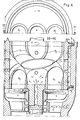
- the charging device works as a rotary charging compressor. 1, it consists of an egg-shaped cross-section housing a, which merges into a cylindrical end part on the pressure side, and of a worm c mounted on the main shaft b with worm threads c1 to c4, whose slope decreases in the direction of pressure and whose diameter is selected so that the outer edges can slide a seal f on the inside of the housing a.
- a controllable diaphragm valve d is provided, which, for. B. is connected to a commercial carburetor, not shown.
- the core or inner diameter of the main shaft b is enlarged in order to achieve an increase in pressure by reducing the volume.
- An antechamber B extending into the cylinder head C connects to the charging device.
- An essential part of the prechamber is a locking ring t, which seals the charging device against the cylinder head C, but at the same time controls the mixture transfer into the cylinder head C.
- the main shaft b has two longitudinal grooves g, the locking ring t additionally having a passage channel t1, the cross section of which can be narrowed or enlarged by an externally actuated locking or rotary slide valve.
- the main shaft b also has a spiral groove g1, which connects the two longitudinal grooves g.
- the inside of this area rotating section of the main shaft b acts as a rotary slide valve and, depending on the rotational position relative to the inlet openings k conducts mixture into a combustion chamber or blocks the outlet of compressed mixture.
- the number of grooves, passage or inlet openings k and the combustion chambers shown can be varied, in deviation from the figure. According to FIG. 3, two combustion chambers 1 which are positioned diagonally to one another are always loaded simultaneously; but it can also be loaded one after the other, especially if the number of combustion chambers is odd. Only the groove g and the inlet openings k and the combustion chambers 1 have to be arranged accordingly.
- the main shaft b has a central bore i which is open at the end and which extends into the antechamber h or up to the height of the inlet openings k and there opens into the groove g via transverse channels.
- This central bore serves, for. B. connect an exhaust gas turbine on the pressure side to increase the boost pressure. So u. U. boost pressures can be achieved that allow the use of diesel fuel.
- each combustion chamber 11 to 14 of the cylinder head C is equipped with a spark plug.
- an injection nozzle for fuel must also be assigned to each combustion chamber, which is not shown in the figure, because this procedure is known from the piston engines.
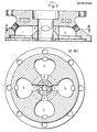
- a control disk D connected to the cylinder head C forwards the combustion gases into an axially adjoining rotary piston E fastened on the main shaft b.
- the rotary slide valve control already described takes place again.
- special measures for sealing have to be taken because the combustion pressures are high.
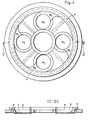
- the rotary slide valve function results from the fact that the rotary piston (four in the example) has combustion pipes p1 to p4, which are arranged on the outer circumference of a cylinder jacket, rotated by 180 ° in the right-hand twist direction, with their upper open ends during rotation under the openings of the control disk and the Can absorb gas pressure.
- the control disk has, on its underside, which faces the rotary piston E, an outer annular groove n which engages in the ribs v1 of the rotating rotary piston E and brings about sealing.
- the control disk D also has gas transfer openings m corresponding to the position of the combustion chambers 11 to 14.
- radial seals o are provided between the gas transfer openings m in order to prevent gas transfer between the openings m.
- the rotary piston E which rotates at a radial distance in a housing, is additionally sealed in the axial direction by means of two ribs v2 which are arranged at an axial distance and engage in the groove v3 of the housing.
- the fuel pipes p1 to p4 for example made of temperature-resistant ceramic material, absorb the fuel gases and convert their energy due to the right-hand twist in the sense of a recoil effect into a torque which is communicated to the main shaft b.
- the output end of the main shaft b is provided with a central bore r2, which is connected via a rotary coupling ra to a pressure source for a liquid cooling medium.
- the cooling medium enters the hollow interior of the rotary piston E from the main shaft b, is thrown outwards after washing around the outside of the combustion tubes p1 to p4, under the action of centrifugal force, and exits through holes r in the jacket of the rotary piston.
- a derivative not shown in detail, takes up the cooling medium and guides it, e.g. B. after passing a cooler, the cooling circuit again.
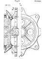
- an exhaust part F or FT connects to the rotary piston E.
- Characteristic of the same is a multi-part housing, - inside which rotors s fastened on the main shaft b rotate.
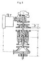
- the charging device is designed as an exhaust gas turbine AT driven by the exhaust gases.
- an exhaust gas turbine FT is provided instead of the exhaust gas screw, in which the last housing section widens conically to accommodate an exhaust gas rotor in the form of an exhaust gas turbine wheel.
- This exhaust gas turbine wheel has a conical solid core, which forms a gap, which preferably becomes smaller in the gas outflow direction, with the housing, convert kinetic energy of the exhaust gas into a torque on or in the turbine blades and feed it to the main shaft.
- FIG. 9 intended to operate turbocompressor AT.
- the feed line of the exhaust gases to the turbocompressor is shown in FIG. 9 with dash-dotted lines.
- the description shows that the explosion turbine engine has no reciprocating parts, thus runs absolutely smoothly and smoothly and no energy is wasted for the acceleration and deceleration of reciprocating parts. There is no knock so that fuel of almost any quality can be used.
- the lubrication of the bearings rotating Parts are completely separated from the guide of rotating surfaces in contact with fuel gases, so that no air pollution from burnt lubricating oil can occur.
- the main advantages are a greater energy utilization of the fuel, a longer service life and an environmentally friendly way of working.
Priority Applications (1)
| Application Number | Priority Date | Filing Date | Title |
|---|---|---|---|
| AT85101430T ATE33698T1 (de) | 1984-02-21 | 1985-02-11 | Explosions-turbinen-motor. |
Applications Claiming Priority (4)
| Application Number | Priority Date | Filing Date | Title |
|---|---|---|---|
| DE19843406187 DE3406187A1 (de) | 1984-02-21 | 1984-02-21 | Explosionsturbine |
| DE3406187 | 1984-02-21 | ||
| DE3503563 | 1985-02-02 | ||
| DE19853503563 DE3503563A1 (de) | 1984-02-21 | 1985-02-02 | Explosions-turbinen-motor |
Publications (2)
| Publication Number | Publication Date |
|---|---|
| EP0154205A1 true EP0154205A1 (fr) | 1985-09-11 |
| EP0154205B1 EP0154205B1 (fr) | 1988-04-20 |
Family
ID=25818670
Family Applications (1)
| Application Number | Title | Priority Date | Filing Date |
|---|---|---|---|
| EP85101430A Expired EP0154205B1 (fr) | 1984-02-21 | 1985-02-11 | Turbine à explosions |
Country Status (3)
| Country | Link |
|---|---|
| US (1) | US4603549A (fr) |
| EP (1) | EP0154205B1 (fr) |
| DE (2) | DE3503563A1 (fr) |
Cited By (1)
| Publication number | Priority date | Publication date | Assignee | Title |
|---|---|---|---|---|
| WO1992008878A1 (fr) * | 1990-11-15 | 1992-05-29 | Pedro Ramos Gomes | Nouvelle turbine helicoidale en profondeur |
Families Citing this family (11)
| Publication number | Priority date | Publication date | Assignee | Title |
|---|---|---|---|---|
| WO2003072917A1 (fr) * | 2002-02-28 | 2003-09-04 | Stanevicius Algimantas Aleksan | Moteur a combustion interne rotatif |
| US7895820B2 (en) * | 2005-11-16 | 2011-03-01 | Techland Research, Inc. | Seal for pulse detonation engine |
| US7963096B2 (en) * | 2006-11-02 | 2011-06-21 | Vanholstyn Alex | Reflective pulse rotary engine |
| US20080310984A1 (en) * | 2007-06-12 | 2008-12-18 | General Electric Company | Positive displacement capture device |
| US20090266047A1 (en) * | 2007-11-15 | 2009-10-29 | General Electric Company | Multi-tube, can-annular pulse detonation combustor based engine with tangentially and longitudinally angled pulse detonation combustors |
| US7905084B2 (en) * | 2008-02-01 | 2011-03-15 | General Electronic Company | Rotary pressure rise combustor for a gas turbine engine |
| US8082728B2 (en) * | 2008-02-01 | 2011-12-27 | General Electric Company | System and method of continuous detonation in a gas turbine engine |
| US10598181B2 (en) * | 2017-11-30 | 2020-03-24 | Rayne Sung | Gas turbine engines and compression systems therefor |
| WO2020256534A1 (fr) * | 2019-06-18 | 2020-12-24 | Stanevicius Algimantas Aleksandras | Moteur rotatif à combustion interne amélioré |
| CN110953937B (zh) * | 2020-02-26 | 2020-05-15 | 长沙玺宸自动化科技有限公司 | 一种粉末混合仿生机械手以及烟花内筒混药系统 |
| WO2023187674A1 (fr) * | 2022-03-30 | 2023-10-05 | Sf Energy Srl | Turbomachine et appareil la comprenant |
Citations (8)
| Publication number | Priority date | Publication date | Assignee | Title |
|---|---|---|---|---|
| FR508098A (fr) * | 1919-12-31 | 1920-10-01 | Turbo-moteur à gaz comprimés | |
| GB271268A (en) * | 1926-06-26 | 1927-05-26 | William Edwin Harvie | Improvements in or relating to internal combustion turbines |
| FR710259A (fr) * | 1931-01-21 | 1931-08-20 | Turbine à explosions | |
| GB373232A (en) * | 1930-11-15 | 1932-05-17 | Eugen Silbermann | Improvements in or relating to turbines, fans and pumps |
| DE2517947A1 (de) * | 1975-04-23 | 1976-10-28 | Messerschmitt Boelkow Blohm | Strahltriebwerk mit einer brennkammer fuer pulsierende verbrennung |
| US4222231A (en) * | 1978-07-20 | 1980-09-16 | Linn Wallace L | Engine |
| GB2062118A (en) * | 1979-11-05 | 1981-05-20 | Covebourne Ltd | Improvements in or relating to a turbine |
| EP0085119A1 (fr) * | 1982-01-29 | 1983-08-10 | Ingelheim gen. Echter v.u.z. Mespelbrunn, Peter, Graf von | Appareil thermodynamique, ayant un compresseur et une section de travail, possédant une introduction de chaleur isobarique, isochorique ou utilisant la combinaison des deux |
Family Cites Families (15)
| Publication number | Priority date | Publication date | Assignee | Title |
|---|---|---|---|---|
| US836945A (en) * | 1905-02-17 | 1906-11-27 | Charles Clarence Poole | Internal-combustion turbine-motor. |
| FR469376A (fr) * | 1914-03-07 | 1914-07-30 | Eugene Caillard | Turbine à explosion |
| US1654119A (en) * | 1925-12-05 | 1927-12-27 | Enders Karl | Internal-combustion turbine with rotary slide valve |
| NL44178C (fr) * | 1934-10-16 | |||
| US2276404A (en) * | 1939-10-10 | 1942-03-17 | Wright Aeronautical Corp | Shrouded impeller |
| FR917953A (fr) * | 1945-11-23 | 1947-01-27 | Moteur-turbine à explosion continue | |
| BE481609A (fr) * | 1947-04-03 | |||
| US2544154A (en) * | 1947-11-14 | 1951-03-06 | Elmer N Hampton | Tubular turbine |
| CH290096A (fr) * | 1947-12-24 | 1953-04-15 | Henry Middleton Vincent | Turbine à combustion interne. |
| US2579321A (en) * | 1948-04-09 | 1951-12-18 | Nina K Guercken | Apparatus for producing gas under pressure |
| FR980166A (fr) * | 1949-02-04 | 1951-05-09 | Moteur à réaction | |
| US2928242A (en) * | 1954-12-16 | 1960-03-15 | Phillips Petroleum Co | Multi-combustion chamber gas turbine with rotary valving |
| FR1131310A (fr) * | 1955-09-19 | 1957-02-20 | Turbine à gaz | |
| DE1231485B (de) * | 1958-11-20 | 1966-12-29 | Bendix Corp | Bremseinrichtung fuer Strassenfahrzeuge mit Gasturbinenantrieb |
| US4157011A (en) * | 1977-08-22 | 1979-06-05 | General Motors Corporation | Gas turbine flywheel hybrid propulsion system |
-
1985
- 1985-02-02 DE DE19853503563 patent/DE3503563A1/de not_active Withdrawn
- 1985-02-11 DE DE8585101430T patent/DE3562286D1/de not_active Expired
- 1985-02-11 EP EP85101430A patent/EP0154205B1/fr not_active Expired
- 1985-02-21 US US06/703,839 patent/US4603549A/en not_active Expired - Fee Related
Patent Citations (8)
| Publication number | Priority date | Publication date | Assignee | Title |
|---|---|---|---|---|
| FR508098A (fr) * | 1919-12-31 | 1920-10-01 | Turbo-moteur à gaz comprimés | |
| GB271268A (en) * | 1926-06-26 | 1927-05-26 | William Edwin Harvie | Improvements in or relating to internal combustion turbines |
| GB373232A (en) * | 1930-11-15 | 1932-05-17 | Eugen Silbermann | Improvements in or relating to turbines, fans and pumps |
| FR710259A (fr) * | 1931-01-21 | 1931-08-20 | Turbine à explosions | |
| DE2517947A1 (de) * | 1975-04-23 | 1976-10-28 | Messerschmitt Boelkow Blohm | Strahltriebwerk mit einer brennkammer fuer pulsierende verbrennung |
| US4222231A (en) * | 1978-07-20 | 1980-09-16 | Linn Wallace L | Engine |
| GB2062118A (en) * | 1979-11-05 | 1981-05-20 | Covebourne Ltd | Improvements in or relating to a turbine |
| EP0085119A1 (fr) * | 1982-01-29 | 1983-08-10 | Ingelheim gen. Echter v.u.z. Mespelbrunn, Peter, Graf von | Appareil thermodynamique, ayant un compresseur et une section de travail, possédant une introduction de chaleur isobarique, isochorique ou utilisant la combinaison des deux |
Cited By (1)
| Publication number | Priority date | Publication date | Assignee | Title |
|---|---|---|---|---|
| WO1992008878A1 (fr) * | 1990-11-15 | 1992-05-29 | Pedro Ramos Gomes | Nouvelle turbine helicoidale en profondeur |
Also Published As
| Publication number | Publication date |
|---|---|
| EP0154205B1 (fr) | 1988-04-20 |
| DE3503563A1 (de) | 1985-08-29 |
| US4603549A (en) | 1986-08-05 |
| DE3562286D1 (en) | 1988-05-26 |
Similar Documents
| Publication | Publication Date | Title |
|---|---|---|
| DE19600679B4 (de) | Schubtriebwerk für Flugzeuge mit Verbundzyklus | |
| DE2916423A1 (de) | Brennkraftmaschine | |
| EP0154205B1 (fr) | Turbine à explosions | |
| DE102008050014A1 (de) | Zink'sche Tangential-Verbrennung Turbine | |
| EP1339952B1 (fr) | Moteur a combustion interne a piston rotatif | |
| DE2851346A1 (de) | Brennkammerturbine | |
| DE4017760A1 (de) | Drehkolbenbrennkraftmaschine | |
| DE19546474C1 (de) | Brennkraftmaschine | |
| DE2909591C2 (de) | Zweitakt-Gegenkolben-Brennkraftmaschine | |
| DE3317431A1 (de) | Viertakt-drehkolbenmotor | |
| DE4119622A1 (de) | Kreiskolbenmotor | |
| DE1916095A1 (de) | Kreiskolben-Brennkraftmaschine | |
| DE4210712A1 (de) | Rotationsmaschine | |
| DE3430613A1 (de) | Rotierende verbrennungskraftmaschine | |
| DE3047138C2 (de) | Freikolben-Brennkraftmaschine | |
| DE3804411A1 (de) | Mittelachsige drehkolbenartige umlaufkolbenmaschine | |
| EP0333883A1 (fr) | Moteur a combustion interne a piston rotatif | |
| DE2429553A1 (de) | Kreiskolbenmotor | |
| DE818277C (de) | Brennkraftturbine fuer Strahlantrieb | |
| EP0166244A2 (fr) | Machine rotative | |
| DE663873C (de) | Brennkraftturbine mit vom Turbinenlaufrade unabhaengig umlaufendem Kolbenverdichter | |
| DE1993284U (de) | Brennkraftmaschine. | |
| DE102020125319B3 (de) | Rotationskolbenmotor | |
| DE402209C (de) | Brennkraftturbine | |
| DE1146698B (de) | Brennkraftkolbenmaschine mit sternfoermig angeordneten umlaufenden Zylindern |
Legal Events
| Date | Code | Title | Description |
|---|---|---|---|
| PUAI | Public reference made under article 153(3) epc to a published international application that has entered the european phase |
Free format text: ORIGINAL CODE: 0009012 |
|
| AK | Designated contracting states |
Designated state(s): AT BE CH DE FR GB IT LI LU NL SE |
|
| 17P | Request for examination filed |
Effective date: 19851017 |
|
| 17Q | First examination report despatched |
Effective date: 19860721 |
|
| D17Q | First examination report despatched (deleted) | ||
| ITF | It: translation for a ep patent filed |
Owner name: BARZANO' E ZANARDO MILANO S.P.A. |
|
| GRAA | (expected) grant |
Free format text: ORIGINAL CODE: 0009210 |
|
| AK | Designated contracting states |
Kind code of ref document: B1 Designated state(s): AT BE CH DE FR GB IT LI LU NL SE |
|
| REF | Corresponds to: |
Ref document number: 33698 Country of ref document: AT Date of ref document: 19880515 Kind code of ref document: T |
|
| GBT | Gb: translation of ep patent filed (gb section 77(6)(a)/1977) | ||
| REF | Corresponds to: |
Ref document number: 3562286 Country of ref document: DE Date of ref document: 19880526 |
|
| ET | Fr: translation filed | ||
| PGFP | Annual fee paid to national office [announced via postgrant information from national office to epo] |
Ref country code: SE Payment date: 19890113 Year of fee payment: 5 Ref country code: FR Payment date: 19890113 Year of fee payment: 5 |
|
| PG25 | Lapsed in a contracting state [announced via postgrant information from national office to epo] |
Ref country code: AT Effective date: 19890211 |
|
| PLBE | No opposition filed within time limit |
Free format text: ORIGINAL CODE: 0009261 |
|
| STAA | Information on the status of an ep patent application or granted ep patent |
Free format text: STATUS: NO OPPOSITION FILED WITHIN TIME LIMIT |
|
| ITTA | It: last paid annual fee | ||
| PG25 | Lapsed in a contracting state [announced via postgrant information from national office to epo] |
Ref country code: LU Free format text: LAPSE BECAUSE OF NON-PAYMENT OF DUE FEES Effective date: 19890228 Ref country code: LI Effective date: 19890228 Ref country code: CH Effective date: 19890228 Ref country code: BE Effective date: 19890228 |
|
| 26N | No opposition filed | ||
| BERE | Be: lapsed |
Owner name: ALBRECHT HANS GERHARD Effective date: 19890228 |
|
| PG25 | Lapsed in a contracting state [announced via postgrant information from national office to epo] |
Ref country code: NL Effective date: 19890901 |
|
| NLV4 | Nl: lapsed or anulled due to non-payment of the annual fee | ||
| REG | Reference to a national code |
Ref country code: CH Ref legal event code: PL |
|
| PGFP | Annual fee paid to national office [announced via postgrant information from national office to epo] |
Ref country code: GB Payment date: 19900131 Year of fee payment: 6 |
|
| PG25 | Lapsed in a contracting state [announced via postgrant information from national office to epo] |
Ref country code: SE Effective date: 19900212 |
|
| PG25 | Lapsed in a contracting state [announced via postgrant information from national office to epo] |
Ref country code: FR Effective date: 19901031 |
|
| REG | Reference to a national code |
Ref country code: FR Ref legal event code: ST |
|
| PGFP | Annual fee paid to national office [announced via postgrant information from national office to epo] |
Ref country code: DE Payment date: 19910206 Year of fee payment: 7 |
|
| PG25 | Lapsed in a contracting state [announced via postgrant information from national office to epo] |
Ref country code: GB Effective date: 19910211 |
|
| GBPC | Gb: european patent ceased through non-payment of renewal fee | ||
| PG25 | Lapsed in a contracting state [announced via postgrant information from national office to epo] |
Ref country code: DE Effective date: 19930901 |
|
| EUG | Se: european patent has lapsed |
Ref document number: 85101430.8 Effective date: 19901107 |