EP0154205A1 - Explosions turbine - Google Patents
Explosions turbine Download PDFInfo
- Publication number
- EP0154205A1 EP0154205A1 EP85101430A EP85101430A EP0154205A1 EP 0154205 A1 EP0154205 A1 EP 0154205A1 EP 85101430 A EP85101430 A EP 85101430A EP 85101430 A EP85101430 A EP 85101430A EP 0154205 A1 EP0154205 A1 EP 0154205A1
- Authority
- EP
- European Patent Office
- Prior art keywords
- main shaft
- turbine engine
- explosion
- engine according
- housing
- Prior art date
- Legal status (The legal status is an assumption and is not a legal conclusion. Google has not performed a legal analysis and makes no representation as to the accuracy of the status listed.)
- Granted
Links
Images


Classifications
-
- F—MECHANICAL ENGINEERING; LIGHTING; HEATING; WEAPONS; BLASTING
- F01—MACHINES OR ENGINES IN GENERAL; ENGINE PLANTS IN GENERAL; STEAM ENGINES
- F01D—NON-POSITIVE DISPLACEMENT MACHINES OR ENGINES, e.g. STEAM TURBINES
- F01D1/00—Non-positive-displacement machines or engines, e.g. steam turbines
- F01D1/34—Non-positive-displacement machines or engines, e.g. steam turbines characterised by non-bladed rotor, e.g. with drilled holes
-
- F—MECHANICAL ENGINEERING; LIGHTING; HEATING; WEAPONS; BLASTING
- F01—MACHINES OR ENGINES IN GENERAL; ENGINE PLANTS IN GENERAL; STEAM ENGINES
- F01L—CYCLICALLY OPERATING VALVES FOR MACHINES OR ENGINES
- F01L7/00—Rotary or oscillatory slide valve-gear or valve arrangements
-
- F—MECHANICAL ENGINEERING; LIGHTING; HEATING; WEAPONS; BLASTING
- F02—COMBUSTION ENGINES; HOT-GAS OR COMBUSTION-PRODUCT ENGINE PLANTS
- F02C—GAS-TURBINE PLANTS; AIR INTAKES FOR JET-PROPULSION PLANTS; CONTROLLING FUEL SUPPLY IN AIR-BREATHING JET-PROPULSION PLANTS
- F02C5/00—Gas-turbine plants characterised by the working fluid being generated by intermittent combustion
- F02C5/12—Gas-turbine plants characterised by the working fluid being generated by intermittent combustion the combustion chambers having inlet or outlet valves, e.g. Holzwarth gas-turbine plants
-
- F—MECHANICAL ENGINEERING; LIGHTING; HEATING; WEAPONS; BLASTING
- F02—COMBUSTION ENGINES; HOT-GAS OR COMBUSTION-PRODUCT ENGINE PLANTS
- F02B—INTERNAL-COMBUSTION PISTON ENGINES; COMBUSTION ENGINES IN GENERAL
- F02B1/00—Engines characterised by fuel-air mixture compression
- F02B1/02—Engines characterised by fuel-air mixture compression with positive ignition
- F02B1/04—Engines characterised by fuel-air mixture compression with positive ignition with fuel-air mixture admission into cylinder
Definitions
- the invention relates to an explosion turbine engine, in particular for road vehicles.
- the known drive motors for motor vehicles are generally piston motors, but they are subject to a limit value for the maximum achievable efficiency because the energy is generated by means of alternately moving parts (pistons, connecting rods, valves, etc.).
- alternately moving parts practides, connecting rods, valves, etc.
- the service life, size and smoothness of such piston internal combustion engines are low because alternately moving parts form unbalances and when the parts are deflected, high acceleration forces have to be generated and absorbed by the parts, resulting in high bearing pressures.
- Wankel motors do not completely eliminate these problems, because the rotor provided instead of the pistons runs epicyclically and is also not circular and centered. There are therefore alternating accelerations and uneven running of the Wankel engine.
- the main disadvantages of the gas turbines are that they work at extremely high speeds and therefore require correspondingly large, expensive reduction gears in order to generate speeds in areas which are suitable for driving motor vehicles.
- One of the biggest disadvantages of the gas turbines is that they do not act as an "engine brake", like piston engines, when driving downhill or the like. Despite overrun cut-off or switching off the fuel supply, there is no braking effect.
- the invention has for its object to provide an explosion turbine engine in which the energy is generated exclusively by means of rotating parts, while at the same time the disadvantages of the previous gas turbines are to be avoided.
- the explosion-turbine engine mentioned at the outset is characterized in accordance with the invention in that in the axial direction on or on a main shaft a charging device in the form of a rotary suction compressor and then in the axial direction a prechamber with a rotary valve inlet control and an injection device, followed by a cylinder head that is fixed like the prechamber with several combustion chambers and at least one spark plug per combustion chamber, followed by an axially fixed control disc with a number of gas passage openings corresponding to the number of combustion chambers, followed by a tubular, fixed housing with it axially revolving piston connected to the main shaft, the has four combustion tubes twisted by 180 ° on the outer edge of a cylindrical jacket in the axial direction with a right-hand twist, axially thereafter in an one-part or multi-part housing an exhaust gas working part with at least one turbine impeller and, like the turbine impeller, an exhaust gas rotor connected to the main shaft and an exhaust gas outlet connection are arranged.
- the loading device is equipped on the air or mixture inlet side with a controllable diaphragm valve.
- the main shaft has two straight-line gas transfer grooves, which are arranged diametrically to one another from the air or mixture outlet end of the charging device via the prechamber to the cylinder head and are connected within the prechamber by means of a spiral groove in the main shaft.
- a rotary suction compressor which, like all other engine parts, is arranged on a common main shaft, takes over the intake and compression of the air if it is an injection engine, or of the air-fuel mixture from a carburetor, if it is a carburetor engine.
- controllable diaphragm valve between the air or mixture suction line and the rotary suction compressor, which not only works as a non-return valve, but can also be mechanically locked in the locked position when the brakes are applied to the engine, thus blocking the air or mixture supply to the charging compressor.
- the resulting failure of the Mixed air flow causes suction and produces a braking effect that can be used as an engine brake.
- the gas passage openings of the control disc which is flanged to the cylinder head, direct the explosion gases to the inlet openings of the combustion tubes of the rotary lobes, which are meanwhile turned to cover.
- the explosion gas flow entering them generates a torque due to the recoil effect, which is communicated to the main shaft.
- the explosion gas emerging from the combustion pipes has by no means given off all of the energy. For this reason, at least one turbine impeller is connected downstream, which takes further energy from the gas and delivers it to the main shaft as torque.
- the energy that is still present in the gas is used again before the outlet by arranging a suitable rotor in the exhaust gas flow.
- the spiral groove in the main shaft which connects the two straight grooves, ensures symmetry of the charge of the combustion chambers of the cylinder head when z.
- the engine can also work with only two or three combustion chambers or combustion chambers and that the combustion chambers can also be loaded one after the other.
- a loading screw is used for the intake compression, which rotates in an egg-shaped housing in axial section with the screw flights sealingly against the inner wall.
- the egg shape changes into a cylindrical shape, with a thickening or diameter enlargement of the screw core or of the main shaft in the area of the cylindrical part increasing the pressure because the volume is reduced.
- a rotary suction compressor in the manner of a known exhaust gas charging turbine can also be used in the known turbo piston engines. Only the diaphragm valve has to be present in order to be able to implement the engine brake, and there has to be a bypass which opens when the diaphragm valve closes for the air coming from the turbocompressor.
- a screw compressor is combined with a turbocompressor; a solution that allows, if necessary, to achieve such high boost pressures that it is possible to work with diesel fuel.
- the special design of the rotary piston according to claim 8 serves on the one hand an exact sealing of the individual combustion tubes and combustion chambers against each other and on the other hand also against the external environment and also the cooling of the combustion pipes.
- the choice of materials is inexpensive and the drive process is environmentally friendly because no lubricating oil films are burned. Since ceramic materials cannot be stored indefinitely against thermal stress, the interchangeability is of great benefit.
- the replacement of the combustion tubes has no great effect on the other components. In the case of a piston engine, wear on the cylinder and piston or the replacement of these are very complex and expensive measures, which almost amount to a general overhaul of the engine.
- the design of the exhaust part depends on how much energy the rotary lobe takes from the exhaust gas flow of the explosion gases. If the energy consumption is large, a single turbine impeller in the exhaust part, which is followed by a rotor shortly before the outlet, is sufficient. However, if the exhaust gases still have usable energy, it is advisable to use two turbine wheels according to claim 9.
- the housing is tapered in order to provide the exhaust gas with a narrowed outflow path, and in the narrowed part a screw adapted to the housing is arranged, which converts the residual energy into a torque and feeds it into the common main shaft.
- a current brake can be arranged on the main shaft according to claim 12, which acts after the current brake of rail vehicles.
- Controllable eddy current brakes which come into question for such purposes, can be used with the help of the sophisticated thyristor or semiconductor technology for energy recovery or feeding of regeneratively generated energy into batteries, so that braking can also be carried out with low energy losses.
- the explosion turbine motor consists of parts which are arranged on a common main shaft b and rotate with it, either acting or being driven, and of an axially multi-part housing which is in relation to the main shaft is fixed and thus enables the various control functions in cooperation with the rotating shaft b.
- the first part is a charging device A or AT.
- the charging device works as a rotary charging compressor. 1, it consists of an egg-shaped cross-section housing a, which merges into a cylindrical end part on the pressure side, and of a worm c mounted on the main shaft b with worm threads c1 to c4, whose slope decreases in the direction of pressure and whose diameter is selected so that the outer edges can slide a seal f on the inside of the housing a.
- a controllable diaphragm valve d is provided, which, for. B. is connected to a commercial carburetor, not shown.
- the core or inner diameter of the main shaft b is enlarged in order to achieve an increase in pressure by reducing the volume.
- An antechamber B extending into the cylinder head C connects to the charging device.
- An essential part of the prechamber is a locking ring t, which seals the charging device against the cylinder head C, but at the same time controls the mixture transfer into the cylinder head C.
- the main shaft b has two longitudinal grooves g, the locking ring t additionally having a passage channel t1, the cross section of which can be narrowed or enlarged by an externally actuated locking or rotary slide valve.
- the main shaft b also has a spiral groove g1, which connects the two longitudinal grooves g.
- the inside of this area rotating section of the main shaft b acts as a rotary slide valve and, depending on the rotational position relative to the inlet openings k conducts mixture into a combustion chamber or blocks the outlet of compressed mixture.
- the number of grooves, passage or inlet openings k and the combustion chambers shown can be varied, in deviation from the figure. According to FIG. 3, two combustion chambers 1 which are positioned diagonally to one another are always loaded simultaneously; but it can also be loaded one after the other, especially if the number of combustion chambers is odd. Only the groove g and the inlet openings k and the combustion chambers 1 have to be arranged accordingly.
- the main shaft b has a central bore i which is open at the end and which extends into the antechamber h or up to the height of the inlet openings k and there opens into the groove g via transverse channels.
- This central bore serves, for. B. connect an exhaust gas turbine on the pressure side to increase the boost pressure. So u. U. boost pressures can be achieved that allow the use of diesel fuel.
- each combustion chamber 11 to 14 of the cylinder head C is equipped with a spark plug.
- an injection nozzle for fuel must also be assigned to each combustion chamber, which is not shown in the figure, because this procedure is known from the piston engines.
- a control disk D connected to the cylinder head C forwards the combustion gases into an axially adjoining rotary piston E fastened on the main shaft b.
- the rotary slide valve control already described takes place again.
- special measures for sealing have to be taken because the combustion pressures are high.
- the rotary slide valve function results from the fact that the rotary piston (four in the example) has combustion pipes p1 to p4, which are arranged on the outer circumference of a cylinder jacket, rotated by 180 ° in the right-hand twist direction, with their upper open ends during rotation under the openings of the control disk and the Can absorb gas pressure.
- the control disk has, on its underside, which faces the rotary piston E, an outer annular groove n which engages in the ribs v1 of the rotating rotary piston E and brings about sealing.
- the control disk D also has gas transfer openings m corresponding to the position of the combustion chambers 11 to 14.
- radial seals o are provided between the gas transfer openings m in order to prevent gas transfer between the openings m.
- the rotary piston E which rotates at a radial distance in a housing, is additionally sealed in the axial direction by means of two ribs v2 which are arranged at an axial distance and engage in the groove v3 of the housing.
- the fuel pipes p1 to p4 for example made of temperature-resistant ceramic material, absorb the fuel gases and convert their energy due to the right-hand twist in the sense of a recoil effect into a torque which is communicated to the main shaft b.
- the output end of the main shaft b is provided with a central bore r2, which is connected via a rotary coupling ra to a pressure source for a liquid cooling medium.
- the cooling medium enters the hollow interior of the rotary piston E from the main shaft b, is thrown outwards after washing around the outside of the combustion tubes p1 to p4, under the action of centrifugal force, and exits through holes r in the jacket of the rotary piston.
- a derivative not shown in detail, takes up the cooling medium and guides it, e.g. B. after passing a cooler, the cooling circuit again.
- an exhaust part F or FT connects to the rotary piston E.
- Characteristic of the same is a multi-part housing, - inside which rotors s fastened on the main shaft b rotate.
- the charging device is designed as an exhaust gas turbine AT driven by the exhaust gases.
- an exhaust gas turbine FT is provided instead of the exhaust gas screw, in which the last housing section widens conically to accommodate an exhaust gas rotor in the form of an exhaust gas turbine wheel.
- This exhaust gas turbine wheel has a conical solid core, which forms a gap, which preferably becomes smaller in the gas outflow direction, with the housing, convert kinetic energy of the exhaust gas into a torque on or in the turbine blades and feed it to the main shaft.
- FIG. 9 intended to operate turbocompressor AT.
- the feed line of the exhaust gases to the turbocompressor is shown in FIG. 9 with dash-dotted lines.
- the description shows that the explosion turbine engine has no reciprocating parts, thus runs absolutely smoothly and smoothly and no energy is wasted for the acceleration and deceleration of reciprocating parts. There is no knock so that fuel of almost any quality can be used.
- the lubrication of the bearings rotating Parts are completely separated from the guide of rotating surfaces in contact with fuel gases, so that no air pollution from burnt lubricating oil can occur.
- the main advantages are a greater energy utilization of the fuel, a longer service life and an environmentally friendly way of working.
Abstract
Explosions - Turbinen - Motor, insbesondere für Strassenfahrzeuge, mit einer Ladeeinrichtung in Form eines Rotations - Saugverdichters (A) an einer Hauptwelle (b) und in Achsrichtung daran anschliessend eine Vorkammer (B) mit einer Drehschieber- Einlasssteuerung (e,g,k) sowie einer Einspritz - Einrichtung (e). Weiter sind vorgesehen ein wie die Vorkammer feststehende Zylinderkopf (C) mit mehreren Verbrennungsräumen (11-14). Daran axial anschliessend eine feststehende Steuerscheibe (D) mit einer der Anzahl der Verbrennungsräume entsprechende Anzahl von Gasdurchtrittsöffnungen (m1 bis m4) mit daran axial anschliessend ein rohrförmiges, feststehendes Gehäuse mit daring umlaufender, mit der Hauptwelle verbundenen Drehkolben (E), der vier am Aussenrand eines zylindrischen Mantels in Achsrichtung mit Rechtsdrall um 180° verwundene Brennrohre (p1 bis p4) aufweist und axial daran anschliessend in einem ein- oder mehrteiligen Gehäuse ein Abgas - Arbeitsteil (F) mit wenigstens einem Turbinenlaufrad (s).Explosion turbine engine, in particular for road vehicles, with a loading device in the form of a rotary suction compressor (A) on a main shaft (b) and then in the axial direction a prechamber (B) with a rotary valve inlet control (e, g, k) and an injection device (e). Furthermore, a cylinder head (C), which is fixed like the prechamber, is provided with several combustion chambers (11-14). Adjoining it axially is a fixed control disc (D) with a number of gas passage openings (m1 to m4) corresponding to the number of combustion chambers, followed by an axially adjoining tubular, fixed housing with a rotating piston (E) surrounding it and connected to the main shaft, the four on the outer edge of a cylindrical jacket in the axial direction with right-hand twist by 180 ° twisted combustion pipes (p1 to p4) and axially adjoining it in a one-part or multi-part housing, an exhaust gas working part (F) with at least one turbine impeller (s).
Description
Die Erfindung betrifft einen Explosions-Turbinen-Motor, insbesondere für Straßenfahrzeuge.The invention relates to an explosion turbine engine, in particular for road vehicles.
Die bekannten Antriebsmotore für Kraftfahrzeuge sind in der Regel Kolbenmotore, die jedoch einem Grenzwert für den maximal erzielbaren Wirkungsgrad unterliegen, weil die Energie mittels alternierend bewegter Teile (Kolben, Pleuel, Ventile usw.) erzeugt wird. Auch die Lebensdauer, Größe und Laufruhe solcher Kolben-Verbrennungsmotore ist gering, weil alternierend bewegte Teile Unwuchten bilden und bei der Bewegungsumlenkung dieser Teile hohe Beschleunigungskräfte erzeugt und von den Teilen aufgenommen werden müssen, wobei sich hohe Lagerdrücke ergeben.The known drive motors for motor vehicles are generally piston motors, but they are subject to a limit value for the maximum achievable efficiency because the energy is generated by means of alternately moving parts (pistons, connecting rods, valves, etc.). The service life, size and smoothness of such piston internal combustion engines are low because alternately moving parts form unbalances and when the parts are deflected, high acceleration forces have to be generated and absorbed by the parts, resulting in high bearing pressures.
Die bekannten Wankelmotoren beseitigen diese Probleme nicht vollständig, denn der anstelle der Kolben vorgesehene Rotor läuft epizyklisch und ist auch nicht kreisrund und zentriert. Es gibt daher auch beim Wankelmotor alternierende Beschleunigungen und Laufunruhe.The known Wankel motors do not completely eliminate these problems, because the rotor provided instead of the pistons runs epicyclically and is also not circular and centered. There are therefore alternating accelerations and uneven running of the Wankel engine.
Es gibt zwar schon Versuchsfahrzeuge mit Gasturbinen bzw. Verbrennungsturbinen als Antrieb, und es sind auch schon Strahltriebwerke in Kraftfahrzeuge eingebaut worden. Reine Strahltriebwerke scheiden als Antrieb für öffentliche Fahrzeuge aus, weil der heiße Gasstrahl eine Gefahr für die Öffentlichkeit darstellt.There are already test vehicles with gas turbines or combustion turbines as drives, and jet engines have already been installed in motor vehicles. Pure jet engines are ruled out as drives for public vehicles because the hot gas jet poses a danger to the public.
Die wesentlichen Nachteile der Gasturbinen bestehen darin, daß diese mit extrem hohen Drehzahlen arbeiten und daher entsprechend große, aufwendige Untersetzungsgetriebe benötigen, um Drehzahlen in Bereichen zu erzeugen, die für den Antrieb von Kraftfahrzeugen geeignet sind. Einer der größten Nachteile der Gasturbinen dürfte jedoch darin bestehen, daß sie nicht, wie Kolbenmotore, als "Motorbremse" wirken, wenn Bergabfahrten o. dgl. dies erfordern. Trotz Schubabschaltung oder Abschaltung der Brennstoffzufuhr ergibt sich keine Bremswirkung.The main disadvantages of the gas turbines are that they work at extremely high speeds and therefore require correspondingly large, expensive reduction gears in order to generate speeds in areas which are suitable for driving motor vehicles. One of the biggest disadvantages of the gas turbines, however, is that they do not act as an "engine brake", like piston engines, when driving downhill or the like. Despite overrun cut-off or switching off the fuel supply, there is no braking effect.
Ausgehend von diesem bekannten Stand der Technik liegt der Erfindung die Aufgabe zugrunde, einen Explosions-Turbinen-Motor zu schaffen, bei dem die Energie ausschließlich mittels rotierender Teile erzeugt wird, während zugleich die Nachteile der bisherigen Gasturbinen vermieden werden sollen.Starting from this known prior art, the invention has for its object to provide an explosion turbine engine in which the energy is generated exclusively by means of rotating parts, while at the same time the disadvantages of the previous gas turbines are to be avoided.
Zur Lösung dieser Aufgabe kennzeichnet sich der eingangs genannte Explosions-Turbinen-Motor gemäß Patentanspruch 1 erfindungsgemäß dadurch, daß in Achsrichtung auf bzw. an einer Hauptwelle eine Ladeeinrichtung in Form eines Rotations-Saugverdichters und in Achsrichtung daran anschließend eine Vorkammer mit einer Drehschieber-Einlaßsteuerung sowie einer Einspritz-Einrichtung, daran anschließend ein wie die Vorkammer feststehender Zylinderkopf mit mehreren Verbrennungsräumen und je Verbrennungsraum wenigstens einer Zündkerze, daran axial anschließend eine feststehende Steuerscheibe mit einer der Anzahl der Verbrennungsräume entsprechenden Anzahl von Gasdurchtrittsöffnungen, daran axial anschließend ein rohrförmiges, feststehendes Gehäuse mit darin umlaufendem, mit der Hauptwelle verbundenen Drehkolben, der vier am Außenrand eines zylindrischen Mantels in Achsrichtung mit Rechtsdrall um 180° verwundene Brennrohre aufweist, axial daran anschließend in einem ein- oder mehrteiligen Gehäuse ein Abgas-Arbeitsteil mit wenigstens einem Turbinenlaufrad und einem, wie das Turbinenlaufrad, mit der Hauptwelle verbundenen Abgasrotor sowie einem Abgasaustrittsstutzen angeordnet sind. Die Ladeeinrichtung ist luft- bzw. gemischeintrittsseitig mit einem ggfs. steuerbaren Membranventil ausgerüstet. Die Hauptwelle weist zwei vom Luft- oder Gemischaustrittsende der Ladeeinrichtung über die Vorkammer bis in den Zylinderkopf diametral zueinander angeordnete, geradlinig verlaufende Gasübertrittsnute auf, die innerhalb der Vorkammer mittels einer Spiralnut der Hauptwelle verbunden sind.To solve this problem, the explosion-turbine engine mentioned at the outset is characterized in accordance with the invention in that in the axial direction on or on a main shaft a charging device in the form of a rotary suction compressor and then in the axial direction a prechamber with a rotary valve inlet control and an injection device, followed by a cylinder head that is fixed like the prechamber with several combustion chambers and at least one spark plug per combustion chamber, followed by an axially fixed control disc with a number of gas passage openings corresponding to the number of combustion chambers, followed by a tubular, fixed housing with it axially revolving piston connected to the main shaft, the has four combustion tubes twisted by 180 ° on the outer edge of a cylindrical jacket in the axial direction with a right-hand twist, axially thereafter in an one-part or multi-part housing an exhaust gas working part with at least one turbine impeller and, like the turbine impeller, an exhaust gas rotor connected to the main shaft and an exhaust gas outlet connection are arranged. The loading device is equipped on the air or mixture inlet side with a controllable diaphragm valve. The main shaft has two straight-line gas transfer grooves, which are arranged diametrically to one another from the air or mixture outlet end of the charging device via the prechamber to the cylinder head and are connected within the prechamber by means of a spiral groove in the main shaft.
Bei dem erfindungsgemäß ausgebildeten Motor übernimmt ein Rotationssaugverdichter, der wie alle anderen Motorteile auf einer gemeinsamen Hauptwelle angeordnet ist, das Ansaugen und Verdichten der Luft, falls es sich um Einspritzmotore handelt, oder des Luft-Kraftstoff-Gemisches aus einem Vergaser, falls es sich um einen Vergasermotor handelt. Wichtiger Vorteil ist, daß sowohl der Vergaser als auch die Einspritzanlage handelsübliche Aggregate für bekannte Kolbenmotoren sein können.In the engine designed according to the invention, a rotary suction compressor, which, like all other engine parts, is arranged on a common main shaft, takes over the intake and compression of the air if it is an injection engine, or of the air-fuel mixture from a carburetor, if it is a carburetor engine. An important advantage is that both the carburetor and the injection system can be commercially available units for known piston engines.
Zwischen der Luft- oder Gemischansaugleitung und dem Rotationssaugverdichter befindet sich ein steuerbares Membranventil, welches nicht nur als Rückschlagventil arbeitet, sondern auch bei Bremsen mit dem Motor mechanisch in der Sperrstellung arretierbar ist und so die Luft- oder Gemischzufuhr zum Ladeverdichter sperrt. Der dadurch entstehende Ausfall des Luft-Gemischstromes verursacht einen Sog und bringt eine Bremswirkung hervor, die als Motorbremse benutzt werden kann.There is a controllable diaphragm valve between the air or mixture suction line and the rotary suction compressor, which not only works as a non-return valve, but can also be mechanically locked in the locked position when the brakes are applied to the engine, thus blocking the air or mixture supply to the charging compressor. The resulting failure of the Mixed air flow causes suction and produces a braking effect that can be used as an engine brake.
Dadurch, daß rotierende und feststehende Teile mit Öffnungen, Schlitzen usw. während der Rotation abwechselnd in Deckungslage zueinander und gegeneinander verschoben sein können, werden Gemisch- bzw. Luft- oder Gaswege periodisch geöffnet oder geschlossen, so daß die Funktionen eines Verbrennungsmotors (Ansaugen, Verdichten, Zünden, Ausstoßen) verwirklicht werden können. So werden über die Vorkammer die vier oder zwei Verbrennungsräume im Zylinderkopf mit verdichtetem Gemisch oder verdichteter Luft gefüllt, anschließend abgesperrt und nach Zündung zur Verbrennung gebracht. Bei Einspritzmotoren hat jede Brennkammer neben der Zündkerze noch eine Einspritzdüse.Due to the fact that rotating and stationary parts with openings, slots, etc. can be shifted alternately in the cover position with respect to one another and against one another, mixture or air or gas paths are periodically opened or closed, so that the functions of an internal combustion engine (suction, compression , Ignition, ejection) can be realized. The four or two combustion chambers in the cylinder head are filled with compressed mixture or compressed air via the prechamber, then shut off and brought to combustion after ignition. In the case of injection engines, each combustion chamber has an injection nozzle in addition to the spark plug.
Sobald der Explosionsvorgang beginnt und sich ein Gasdruck aufbaut, der zur Arbeitsleistung geeignet ist, leiten die Gasdurchtrittsöffnungen der Steuerscheibe, die an den Zylinderkopf angeflanscht ist, die Explosionsgase an die inzwischen in Deckungslage gedrehten Eingangsöffnungen der Brennrohre des Drehkolbens. Infolge der gewundenen oder verdrallten Form der Brennrohre erzeugt der in diese eintretende Explosionsgasstrom infolge Rückstoßwirkung ein Drehmoment, das der Hauptwelle mitgeteilt wird.As soon as the explosion process begins and a gas pressure builds up, which is suitable for the work, the gas passage openings of the control disc, which is flanged to the cylinder head, direct the explosion gases to the inlet openings of the combustion tubes of the rotary lobes, which are meanwhile turned to cover. As a result of the tortuous or twisted shape of the combustion tubes, the explosion gas flow entering them generates a torque due to the recoil effect, which is communicated to the main shaft.
Das aus den Brennrohren austretende Explosionsgas hat noch längst nicht alle Energie abgegeben. Deshalb ist wenigstens ein Turbinenlaufrad nachgeschaltet, das weitere Energie aus dem Gas entnimmt und als Drehmoment auf die Hauptwelle abgibt.The explosion gas emerging from the combustion pipes has by no means given off all of the energy. For this reason, at least one turbine impeller is connected downstream, which takes further energy from the gas and delivers it to the main shaft as torque.
Die im Gas immer noch vorhandene Energie wird vor dem Austritt noch einmal genutzt, indem ein geeigneter Rotor im Abgasstrom angeordnet wird.The energy that is still present in the gas is used again before the outlet by arranging a suitable rotor in the exhaust gas flow.
Alle diese Vorgänge sind reine Rotationsvorgänge. Alle Zubehöreinrichtungen, wie Zündeinrichtung, Kühlanlage, Schmieranlage usw., sind handelsübliche Aggregate bekannter Kolbenmotoren.All of these processes are pure rotation processes. All accessories, such as the ignition device, cooling system, lubrication system, etc., are commercially available units of known piston engines.
Alle diese das Drehmoment erzeugenden Vorgänge wirken unwuchtfrei ohne alternierende Bewegungen auf die gemeinsame Hauptwelle. Es wird während der Rotation keine Energie zur Beschleunigung oder Abbremsung irgendwelcher Bauteile verschwendet.All of these torque-generating processes act unbalanced without alternating movements on the common main shaft. No energy is wasted during acceleration to accelerate or slow down any component.
Die spiralförmige Nut in der Hauptwelle, die die beiden geradlinigen Nute verbindet, sichert Symmetrie der Ladung der Verbrennungsräume des Zylinderkopfes, wenn z. B. zwei diametral gegenüberliegende Brennräume geladen werden sollen. Lediglich der Vollständigkeit halber sei erwähnt, daß der Motor auch mit nur zwei oder drei Brennkammern bzw. Brennräumen arbeiten kann, und daß die Brennräume auch einzeln nacheinander geladen werden können.The spiral groove in the main shaft, which connects the two straight grooves, ensures symmetry of the charge of the combustion chambers of the cylinder head when z. B. two diametrically opposite combustion chambers are to be loaded. For the sake of completeness, it should be mentioned that the engine can also work with only two or three combustion chambers or combustion chambers and that the combustion chambers can also be loaded one after the other.
Bei der Weiterbildung nach Patentanspruch 2 dient zur Ansaugverdichtung eine Ladeschnecke, die in einem im Axialschnitt eiförmigen Gehäuse mit den Schneckengängen dichtend an der Innenwand anliegend rotiert. Druckseitig geht die Eiform in eine Zylinderform über, wobei eine Verdickung oder Durchmesservergrößerung des Schneckenkernes bzw. der Hauptwelle im Bereich des zylindrischen Teiles drucksteigernd wirkt, weil das Volumen verkleinert wird. Alternativ zur Ladeschnecke kann gemäß Patentanspruch 3 auch ein Rotations-Saugverdichter nach Art einer bekannten Abgas-Ladeturbine bei den bekannten Turbo-Kolbenmotoren angewendet werden. Es muß lediglich das Membranventil vorhanden sein, um die Motorbremse verwirklichen zu können, und es muß einen Nebenweg geben, der sich beim Schließen des Membranventiles für die vom Turboverdichter kommende Luft öffnet.In the development according to claim 2, a loading screw is used for the intake compression, which rotates in an egg-shaped housing in axial section with the screw flights sealingly against the inner wall. On the pressure side, the egg shape changes into a cylindrical shape, with a thickening or diameter enlargement of the screw core or of the main shaft in the area of the cylindrical part increasing the pressure because the volume is reduced. As an alternative to the charging screw, a rotary suction compressor in the manner of a known exhaust gas charging turbine can also be used in the known turbo piston engines. Only the diaphragm valve has to be present in order to be able to implement the engine brake, and there has to be a bypass which opens when the diaphragm valve closes for the air coming from the turbocompressor.
Bei der Weiterbildung nach Patentanspruch 4 ist ein Schneckenverdichter mit einem Turboverdichter kombiniert; eine Lösung, die ggfs. so hohe Ladedrücke zu erzielen gestattet, daß mit Dieseltreibstoff gearbeitet werden kann.In the development according to claim 4, a screw compressor is combined with a turbocompressor; a solution that allows, if necessary, to achieve such high boost pressures that it is possible to work with diesel fuel.
Um die Ladesteuerung exakt umlaufgerecht durchzuführen, ist die Weiterbildung nach Patentanspruch 5 geeignet.In order to carry out the charge control exactly in line with the circulation, the further development according to claim 5 is suitable.
Zur Optimierung der Ladefunktion dient auch die Weiterbildung nach Patentanspruch 6, insbesondere ist aber mittels des ggfs. von Hand betätigbaren Schiebers eine zusätzliche Steuerung bzw. Wirkungssteigerung der Motorbremse erzielbar.The further development according to claim 6 also serves to optimize the charging function, but in particular an additional control or increase in the effectiveness of the engine brake can be achieved by means of the slide, which may be actuated by hand.
Die Weiterbildung nach Patentanspruch 7 dient einer exakten Steuerung des Gasübertrittes und der Vermeidung von Druck- bzw. Gasverlusten nach außen sowie zwischen den einzelnen Brennräumen; die Aussparungen erlauben eine Umkehrspülung der Brennräume vor der erneuten Ladung.The further development according to claim 7 serves to precisely control the gas transfer and to avoid pressure or gas losses to the outside and between the individual combustion chambers; the recesses allow the combustion chambers to be flushed before being reloaded.
Die besondere Gestaltung des Drehkolbens nach Patentanspruch 8 dient einerseits einer exakten Abdichtung der einzelnen Brennrohre und Brennräume gegeneinander und andererseits auch gegenüber der äußeren Umgebung und darüber hinaus der Kühlung der Brennrohre. Die Materialwahl ist preiswert und der Antriebsvorgang umweltfreundlich, weil keine Schmierölfilme verbrannt werden. Da auch keramische Werkstoffe gegen Temperaturbelastung nicht unbegrenzt haltbar sind, ist die Auswechselbarkeit von großem Nutzen. Gegenüber Kolbenmotoren, deren Zylinder mit Kolben in etwa das Äquivalent der Brennrohre des erfindungsgemäß ausgebildeten Motors darstellen, hat das Auswechseln der Brennrohre keine große Wirkung auf die anderen Bauteile. Bei einem Kolbenmotor sind Verschleiß von Zylinder und Kolben bzw. der Austausch derselben sehr aufwendige und teure Maßnahmen, die fast einer General- überholung des Motors gleichkommen.The special design of the rotary piston according to claim 8 serves on the one hand an exact sealing of the individual combustion tubes and combustion chambers against each other and on the other hand also against the external environment and also the cooling of the combustion pipes. The choice of materials is inexpensive and the drive process is environmentally friendly because no lubricating oil films are burned. Since ceramic materials cannot be stored indefinitely against thermal stress, the interchangeability is of great benefit. Compared to piston engines, whose cylinders with pistons represent approximately the equivalent of the combustion tubes of the engine designed according to the invention, the replacement of the combustion tubes has no great effect on the other components. In the case of a piston engine, wear on the cylinder and piston or the replacement of these are very complex and expensive measures, which almost amount to a general overhaul of the engine.
Die Ausgestaltung des Abgasteiles hängt davon ab, wieviel Energie der Drehkolben aus dem Abgasstrom der Explosionsgase entnimmt. Ist die Energieentnahme groß, so genügt ein einziges Turbinenlaufrad im Abgasteil, dem kurz vor Austritt noch ein Rotor nachgeschaltet ist. Haben die Abgase jedoch noch verwertbare Energie, so empfiehlt es sich, nach Patentanspruch 9 zwei Turbinenräder zu verwenden.The design of the exhaust part depends on how much energy the rotary lobe takes from the exhaust gas flow of the explosion gases. If the energy consumption is large, a single turbine impeller in the exhaust part, which is followed by a rotor shortly before the outlet, is sufficient. However, if the exhaust gases still have usable energy, it is advisable to use two turbine wheels according to claim 9.
Die Ausgestaltung des letzten Abgasteiles.ist nach zwei Alternativen möglich. Bei der Ausführung nach Patentanspruch 10 ist das Gehäuse konisch verjüngt, um dem Abgas einen verengten Ausströmweg zu bieten, und im verengten Teil ist eine dem Gehäuse angepaßte Schnecke angeordnet, die die Restenergie in ein Drehmoment umwandelt und in die gemeinsame Hauptwelle einspeist. Es handelt sich bei dieser Lösung um die Ausführung in kompakter, kleinvolumiger Bauweise.The design of the last exhaust section is possible according to two alternatives. In the embodiment according to claim 10, the housing is tapered in order to provide the exhaust gas with a narrowed outflow path, and in the narrowed part a screw adapted to the housing is arranged, which converts the residual energy into a torque and feeds it into the common main shaft. This solution is a compact, small-volume design.
Die andere Lösung bietet die Weiterbildung nach Patentanspruch 11, bei der ein Abgas-Turbinenrad mit großem Durchmesser und mit konischem Kern zur Einengung des Querschnittes der Verbrennungsgase vorgesehen ist, um die Restenergie der Abgase in ein Drehmoment umzuwandeln.The other solution is offered by the development according to
Zur Steigerung der Abbremswirkung kann gemäß Patentanspruch 12 auf der Hauptwelle eine Strombremse angeordnet sein, die nach der Strombremse von Schienenfahrzeugen wirkt. Regelbare Wirbelstrombremsen, die für solche Zwecke in Frage kommen, können mit Hilfe der ausgereiften Thyristor- bzw. Halbleitertechnik zur Energierückgewinnung bzw. Einspeisung generatorisch erzeugter Energie in Batterien verwendet werden, so daß auch die Bremsung mit geringen Energieverlusten durchführbar wird.To increase the braking effect, a current brake can be arranged on the main shaft according to
Ausführungsbeispiele des erfindungsgemäß ausgebildeten Explosions-Turbinen-Motors sind in den Zeichnungen dargestellt. Es zeigt:
- Fig. 1 - einen Schemaaxialschnitt durch den Saugkompressor der Ladeeinrichtung bei Ausbildung als Ladeschnecke,
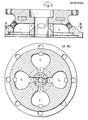
- Fig. 2 - einen Axialschemaschnitt durch die Vorkammer und den Zylinderkopf,
- Fig. 3 - eine Axial-Schemaschnittansicht und einen Schnitt längs der Linie A - B des Schnittes, der die Vorkammer und den Zylinderkopf ohne Hauptwelle wiedergibt,
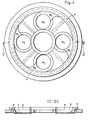
- Fig. 4 - eine Draufsicht und eine Axialschnittansicht-der Steuerplatte,
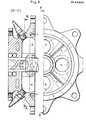
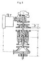
- Fig. 5 - eine Axialschnittansicht des Zylinderkopfes mit Hauptwelle und Steuerplatte und eine Unteransicht dieser Teile,
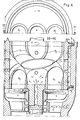
- Fig. 6 - eine Teildraufsicht und eine Axialschnittansicht des Drehkolbens mit anschließendem Abgasteil,
- Fig. 7 - eine teils geschnittene perspektivische Ansicht des Drehkolbens,
- Fig. 8 - eine auseinandergerückte Axialschnittansicht einer Ausführungsform des Explosions-Turbinen-Motors und
- Fig. 9 - eine der Fig. 8 entsprechende Darstellung einer weiteren Ausführungsform des Explosions-Turbinen-Motors.
- 1 - a schematic axial section through the suction compressor of the charging device when designed as a loading screw,
- 2 - an axial schematic section through the prechamber and the cylinder head,
- 3 - an axial schematic sectional view and a section along the line A - B of the section which shows the prechamber and the cylinder head without a main shaft,
- 4 - a top view and an axial sectional view of the control plate,
- 5 - an axial sectional view of the cylinder head with main shaft and control plate and a bottom view of these parts,
- 6 - a partial top view and an axial sectional view of the rotary piston with subsequent exhaust part,
- 7 - a partially sectioned perspective view of the rotary piston,
- Fig. 8 - an exploded axial sectional view of an embodiment of the explosion turbine engine and
- FIG. 9 - a representation corresponding to FIG. 8 of a further embodiment of the explosion turbine engine.
Wie die Figuren zeigen, besteht der Explosions-Turbinen-Motor aus Teilen, die auf einer gemeinsamen Hauptwelle b angeordnet sind und mit dieser rotieren, wobei sie entweder antreibend wirken oder getrieben werden und aus einem in Achsrichtung mehrteiligen Gehäuse, welches in Bezug auf die Hauptwelle feststeht und so die diversen Steuerfunktionen im Zusammenwirken mit der rotierenden Welle b ermöglicht.As the figures show, the explosion turbine motor consists of parts which are arranged on a common main shaft b and rotate with it, either acting or being driven, and of an axially multi-part housing which is in relation to the main shaft is fixed and thus enables the various control functions in cooperation with the rotating shaft b.
In Funktionsrichtung gesehen ist der erste Teil eine Ladeeinrichtung A oder AT. Die Ladeeinrichtung arbeitet als Rotations-Ladeverdichter. Gemäß Fig. 1 besteht sie aus einem im Querschnitt eiförmigen Gehäuse a, das druckseitig in einen zylindrischen Endteil übergeht, sowie aus einer auf der Hauptwelle b montierten Schnecke c mit Schneckengängen c1 bis c4, deren Steigung in Druckrichtung abnimmt und deren Durchmesser jeweils so gewählt ist, daß die Außenkanten mittels einer Dichtung f an der Innenseite des Gehäuses a gleiten können.Seen in the functional direction, the first part is a charging device A or AT. The charging device works as a rotary charging compressor. 1, it consists of an egg-shaped cross-section housing a, which merges into a cylindrical end part on the pressure side, and of a worm c mounted on the main shaft b with worm threads c1 to c4, whose slope decreases in the direction of pressure and whose diameter is selected so that the outer edges can slide a seal f on the inside of the housing a.
Saugseitig ist ein steuerbares Membranventil d vorgesehen, das z. B. mit einem nicht gezeigten handelsüblichen Vergaser in Verbindung steht. Am Druckende der Schnecke c ist der Kern oder Innendurchmesser der Hauptwelle b vergrößert, um eine Drucksteigerung durch Volumenverkleinerung zu erzielen.On the suction side, a controllable diaphragm valve d is provided, which, for. B. is connected to a commercial carburetor, not shown. At the pressure end of the screw c, the core or inner diameter of the main shaft b is enlarged in order to achieve an increase in pressure by reducing the volume.
An die Ladeeinrichtung schließt sich eine bis in den Zylinderkopf C reichende Vorkammer B an. Wesentlicher Bestandteil der Vorkammer ist ein Sperring t, der die Ladeeinrichtung gegen den Zylinderkopf C abdichtet, jedoch zugleich den Gemischübertritt in den Zylinderkopf C steuert. Innerhalb des Sperrringes t hat die Hauptwelle b zwei Längsnute g, wobei der Sperring t zusätzlich einen Durchtrittskanal t1 aufweist, dessen Querschnitt von einem von außen betätigbaren Sperr- oder Drehschieber verengt oder vergrößert werden kann.An antechamber B extending into the cylinder head C connects to the charging device. An essential part of the prechamber is a locking ring t, which seals the charging device against the cylinder head C, but at the same time controls the mixture transfer into the cylinder head C. Within the locking ring t, the main shaft b has two longitudinal grooves g, the locking ring t additionally having a passage channel t1, the cross section of which can be narrowed or enlarged by an externally actuated locking or rotary slide valve.
Im Anschluß an den Teil, der noch innerhalb der Ladeeinrichtung A bzw. des Sperringes t liegt, befindet sich die eigentliche Vorkammer h, in der die Hauptwelle allseitig vom Gehäuse umgeben rotiert. In diesem Bereich trägt die Hauptwelleb noch eine Spiralnut g1, die die beiden Längsnute g verbindet.Following the part that is still within the charging device A or the locking ring t, there is the actual prechamber h, in which the main shaft rotates on all sides surrounded by the housing. In this area, the main shaft b also has a spiral groove g1, which connects the two longitudinal grooves g.
Am Ende der Nute g befinden sich, teils als Bestandteil der Vorkammer B bzw. h, teils als Bestandteil des Zylinderkopfes C, vier Einlaßöffnungen k, die in drei oder vier Brennkammern oder Brennräume 11 bis 14 münden, wobei der innerhalb dieses Bereiches rotierende Abschnitt der Hauptwelle b als Drehschieber fungiert und je nach Drehstellung relativ zu den Eintrittsöffnungen k verdichtetes Gemisch in eine Brennkammer leitet oder den Austritt verdichteten Gemisches sperrt. Die gezeigte Anzahl der Nute, Durchtritts- oder Einlaßöffnungen k und der Brennräume ist, abweichend von der Figur, variierbar. Gemäß Fig. 3 werden immer zwei diagonal zueinander stehende Brennkammern 1 zugleich geladen; es kann aber auch, insbesondere bei ungeradzahliger Brennraumzahl, einzeln nacheinander geladen werden. Es müssen nur die Nute g und die Eintrittsöffnungen k sowie die Brennräume 1 entsprechend angeordnet werden.At the end of the groove g there are four inlet openings k, partly as part of the prechamber B or h, partly as part of the cylinder head C, which open into three or four combustion chambers or
Bei der Ausführung nach Fig. 1 hat die Hauptwelle b eine am Ende offene Zentralbohrung i, die bis in die Vorkammer h bzw. bis zur Höhe der Eintrittsöffnungen k reicht und dort über Querkanäle in die Nute g mündet. Diese Zentralbohrung dient dazu, z. B. eine Abgasladeturbine druckseitig anzuschließen, um den Ladedruck zu erhöhen. So können u. U. Ladedrücke erzielt werden, die die Verwendung von Dieselkraftstoff gestatten.In the embodiment according to FIG. 1, the main shaft b has a central bore i which is open at the end and which extends into the antechamber h or up to the height of the inlet openings k and there opens into the groove g via transverse channels. This central bore serves, for. B. connect an exhaust gas turbine on the pressure side to increase the boost pressure. So u. U. boost pressures can be achieved that allow the use of diesel fuel.
Für den normalen Betrieb mit Benzin ist jeder Brennraum 11 bis 14 des Zylinderkopfes C mit einer Zündkerze ausgerüstet. Sollte jedoch mit Kraftstoffeinspritzung gearbeitet werden, so ist jedem Brennraum auch noch eine Einspritzdüse für Kraftstoff zuzuordnen, was in der Figur nicht gezeigt ist, weil dieses Vorgehen von den Kolbenmotoren her bekannt ist.For normal operation with gasoline, each
Die Zündung der Zündkerzen z erfolgt mit Hilfe einer von Kolbenmotoren her bekannten Zündanlage und ist daher in den Figuren nicht einzeln dargestellt.The ignition of the spark plugs z takes place with the aid of an ignition system known from piston engines and is therefore not shown individually in the figures.
Wird das entweder schon angesaugte und verdichtete oder durch Einspritzung in verdichtete Luft erzeugte Gemisch gezündet, baut sich in den Brennräumen ein Explosionsdruck auf.If the mixture that has either been sucked in and compressed or ignited by injection into compressed air is ignited, an explosion pressure builds up in the combustion chambers.
Eine an den Zylinderkopf C angeschlossene Steuerscheibe D.leitet die Verbrennungsgase in einen axial anschließenden, auf der Hauptwelle b befestigten Drehkolben E weiter. Auch beim Zusammenwirken der feststehenden Steuerscheibe D mit dem rotierenden Drehkolben E findet wieder die schon-beschriebene Drehschiebersteuerung statt. Es müssen jedoch besondere Maßnahmen für die Abdichtung ergriffen werden, weil die Brenndrücke hoch sind. Die Drehschieberfunktion ergibt sich dadurch, daß der Drehkolben (im Beispiel vier) Brennrohre p1 bis p4 aufweist, die am Außenumfang eines Zylindermantels in Rechtsdrallrichtung um 180° verdreht angeordnet sind, mit ihren oberen offenen Enden während der Rotation unter die Öffnungen der Steuerscheibe treten und den Gasdruck aufnehmen können. Zwecks Abdichtung hat die Steuerscheibe auf ihrer Unterseite, die dem Drehkolben E zugewandt ist, eine äußere kreisringförmig verlaufende Nut n, die in die Rippen v1 des rotierenden Drehkolbens E eingreifen und Abdichtung bewirken.A control disk D connected to the cylinder head C forwards the combustion gases into an axially adjoining rotary piston E fastened on the main shaft b. Even when the fixed control disk D interacts with the rotating rotary piston E, the rotary slide valve control already described takes place again. However, special measures for sealing have to be taken because the combustion pressures are high. The rotary slide valve function results from the fact that the rotary piston (four in the example) has combustion pipes p1 to p4, which are arranged on the outer circumference of a cylinder jacket, rotated by 180 ° in the right-hand twist direction, with their upper open ends during rotation under the openings of the control disk and the Can absorb gas pressure. For the purpose of sealing, the control disk has, on its underside, which faces the rotary piston E, an outer annular groove n which engages in the ribs v1 of the rotating rotary piston E and brings about sealing.
Die Steuerscheibe D hat außerdem Gasübertrittsöffnungen m entsprechend der Lage der Brennräume 11 bis 14. Zusätzlich sind zwischen den Gasübertrittsöffnungen m radial verlaufende Dichtungen o vorgesehen, um einen Gasübertritt zwischen den öffnungen m zu verhindern.The control disk D also has gas transfer openings m corresponding to the position of the
Der Drehkolben E, der mit radialem Abstand in einem Gehäuse umläuft, ist mittels zweier in axialem Abstand angeordneter, in Nute v3 des Gehäuses eingreifender Rippen v2 zusätzlich in Achsrichtung abgedichtet. Die bspw. aus temperaturbeständigem keramischen Werkstoff bestehenden Brennrohre p1 bis p4 nehmen die Brenngase auf und wandeln deren Energie infolge des Rechtsdralles im Sinne eines Rückstoßeffektes in ein Drehmoment um, das der Hauptwelle b mitgeteilt wird.The rotary piston E, which rotates at a radial distance in a housing, is additionally sealed in the axial direction by means of two ribs v2 which are arranged at an axial distance and engage in the groove v3 of the housing. The fuel pipes p1 to p4, for example made of temperature-resistant ceramic material, absorb the fuel gases and convert their energy due to the right-hand twist in the sense of a recoil effect into a torque which is communicated to the main shaft b.
Zur Kühlung ist das Abtriebsende der Hauptwelle b mit einer Zentralbohrung r2 versehen, welche über eine Drehkupplung ra mit einer Druckquelle für ein flüssiges Kühlmedium in Verbindung steht. Das Kühlmedium tritt aus der Hauptwelle b in den hohlen Innenraum des Drehkolbens E ein, wird nach Umspülung der Außenseiten der Brennrohre p1 bis p4 nach außen geschleudert, und zwar unter Fliehkraftwirkung, und tritt durch Löcher r im Mantel des Drehkolbens aus. Eine im einzelnen nicht gezeigte Ableitung nimmt das Kühlmedium auf und führt es, z. B. nach Passieren eines Kühlers, dem Kühlkreislauf wieder zu.For cooling, the output end of the main shaft b is provided with a central bore r2, which is connected via a rotary coupling ra to a pressure source for a liquid cooling medium. The cooling medium enters the hollow interior of the rotary piston E from the main shaft b, is thrown outwards after washing around the outside of the combustion tubes p1 to p4, under the action of centrifugal force, and exits through holes r in the jacket of the rotary piston. A derivative, not shown in detail, takes up the cooling medium and guides it, e.g. B. after passing a cooler, the cooling circuit again.
Im Drehkolben kann nur die erste große Verpuffungsenergie genutzt werden. Deshalb schließt sich an den Drehkolben E ein Abgasteil F oder FT an.Only the first large deflagration energy can be used in the rotary lobe. Therefore, an exhaust part F or FT connects to the rotary piston E.
Kennzeichen desselben ist ein mehrteiliges Gehäuse, - in dessen Innerem auf der Hauptwelle b befestigte Rotoren s rotieren.Characteristic of the same is a multi-part housing, - inside which rotors s fastened on the main shaft b rotate.
Im Anschluß an das Austrittsende des Drehkolbens E befindet sich auf der Hauptwelle wenigstens ein Turbinenrad s, gemäß Fig. 8 ist in axialem Abstand, in welchem sich ein feststehender Schaufelstator befindet, ein weiteres Turbinenlaufrad angeordnet. In einem weiteren sich verjüngenden Gehäuseabschnitt befindet sich eine entsprechend in Ausgangsrichtung des Brenngases verjüngte Schnecke, die die Restenergie der Verbrennungsgase ausnutzt und der Hauptwelle als Drehmoment zuführt, bevor die Auspuffgase seitlich über einen Stutzen abgeführt werden.Following the outlet end of the rotary piston E, there is at least one turbine wheel s on the main shaft, as shown in FIG. 8 is at an axial distance, in which there is a fixed blade stator det, another turbine impeller arranged. In a further tapered housing section there is a screw tapered in the exit direction of the fuel gas, which uses the residual energy of the combustion gases and supplies the main shaft as torque before the exhaust gases are discharged laterally via a nozzle.
Bei der Ausgestaltung nach Fig. 9 ist die Ladeeinrichtung als von den Auspuffgasen angetriebene Abgasturbine AT ausgebildet. Außerdem ist anstelle der Abgasschnecke eine Abgasturbine FT vorgesehen, bei der sich der letzte Gehäuseabschnitt konisch erweitert, um einen Abgasrotor in Form eines Abgasturbinenrades aufzunehmen. Dieses Abgasturbinenrad hat einen kegelförmigen festen Kern, der mit dem Gehäuse einen vorzugsweise in Gasabströmrichtung kleiner werdenden Spalt bildet, auf bzw. in dem Turbinenschaufeln kinetische Energie des Abgases in ein Drehmoment umwandeln und der Hauptwelle zuführen.9, the charging device is designed as an exhaust gas turbine AT driven by the exhaust gases. In addition, an exhaust gas turbine FT is provided instead of the exhaust gas screw, in which the last housing section widens conically to accommodate an exhaust gas rotor in the form of an exhaust gas turbine wheel. This exhaust gas turbine wheel has a conical solid core, which forms a gap, which preferably becomes smaller in the gas outflow direction, with the housing, convert kinetic energy of the exhaust gas into a torque on or in the turbine blades and feed it to the main shaft.
Unabhängig davon, ob eine Abgasschnecke oder eine Abgasturbine vorgesehen ist, reicht die enthaltene Restenergie immer noch aus, um den gem. Fig. 9 vorgesehenen Turboverdichter AT zu betreiben. Die Zuleitung der Abgase zum Turboverdichter ist in Fig. 9 mit strichpunktierten Linien wiedergegeben.Regardless of whether an exhaust screw or an exhaust gas turbine is provided, the residual energy contained is still sufficient to meet the gem. Fig. 9 intended to operate turbocompressor AT. The feed line of the exhaust gases to the turbocompressor is shown in FIG. 9 with dash-dotted lines.
Die Beschreibung zeigt, daß der Explosions-Turbinen-Motor keine hin- und hergehenden Teile aufweist, somit absolut rund und ruhig läuft und keine Energie für die Beschleunigung und Abbremsung hin- und hergehender Teile vergeudet. Es gibt kein Klopfen, so daß Treibstoff nahezu beliebiger Qualität verwendet werden kann. Die Schmierung der Lager rotierender Teile ist von der Führung rotierender, von Brenngasen berührter Flächen absolut abgetrennt, so daß keine Luftverschmutzung durch verbranntes Schmieröl auftreten kann. Eine größere Energieausnutzung des Treibstoffes, eine längere Lebensdauer und eine umweltfreundliche Arbeitsweise sind die wesentlichen Vorteile.The description shows that the explosion turbine engine has no reciprocating parts, thus runs absolutely smoothly and smoothly and no energy is wasted for the acceleration and deceleration of reciprocating parts. There is no knock so that fuel of almost any quality can be used. The lubrication of the bearings rotating Parts are completely separated from the guide of rotating surfaces in contact with fuel gases, so that no air pollution from burnt lubricating oil can occur. The main advantages are a greater energy utilization of the fuel, a longer service life and an environmentally friendly way of working.
Alle in der Beschreibung und/oder den Zeichnungen dargestellten Einzel- und Kombinationsmerkmale werden als erfindungswesentlich angesehen.All individual and combination features shown in the description and / or the drawings are considered essential to the invention.
Claims (12)
dadurch gekennzeichnet,
characterized,
Priority Applications (1)
| Application Number | Priority Date | Filing Date | Title |
|---|---|---|---|
| AT85101430T ATE33698T1 (en) | 1984-02-21 | 1985-02-11 | EXPLOSION TURBINE ENGINE. |
Applications Claiming Priority (4)
| Application Number | Priority Date | Filing Date | Title |
|---|---|---|---|
| DE3406187 | 1984-02-21 | ||
| DE19843406187 DE3406187A1 (en) | 1984-02-21 | 1984-02-21 | Explosion turbine |
| DE19853503563 DE3503563A1 (en) | 1984-02-21 | 1985-02-02 | EXPLOSION TURBINE ENGINE |
| DE3503563 | 1985-02-02 |
Publications (2)
| Publication Number | Publication Date |
|---|---|
| EP0154205A1 true EP0154205A1 (en) | 1985-09-11 |
| EP0154205B1 EP0154205B1 (en) | 1988-04-20 |
Family
ID=25818670
Family Applications (1)
| Application Number | Title | Priority Date | Filing Date |
|---|---|---|---|
| EP85101430A Expired EP0154205B1 (en) | 1984-02-21 | 1985-02-11 | Explosions turbine |
Country Status (3)
| Country | Link |
|---|---|
| US (1) | US4603549A (en) |
| EP (1) | EP0154205B1 (en) |
| DE (2) | DE3503563A1 (en) |
Cited By (1)
| Publication number | Priority date | Publication date | Assignee | Title |
|---|---|---|---|---|
| WO1992008878A1 (en) * | 1990-11-15 | 1992-05-29 | Pedro Ramos Gomes | New turbine helicoidal in depth |
Families Citing this family (11)
| Publication number | Priority date | Publication date | Assignee | Title |
|---|---|---|---|---|
| US7124571B2 (en) * | 2002-02-28 | 2006-10-24 | Stanevicius Algimantas Aleksan | Rotary internal combustion engine |
| US7895820B2 (en) * | 2005-11-16 | 2011-03-01 | Techland Research, Inc. | Seal for pulse detonation engine |
| US7963096B2 (en) * | 2006-11-02 | 2011-06-21 | Vanholstyn Alex | Reflective pulse rotary engine |
| US20080310984A1 (en) * | 2007-06-12 | 2008-12-18 | General Electric Company | Positive displacement capture device |
| US20090266047A1 (en) * | 2007-11-15 | 2009-10-29 | General Electric Company | Multi-tube, can-annular pulse detonation combustor based engine with tangentially and longitudinally angled pulse detonation combustors |
| US7905084B2 (en) * | 2008-02-01 | 2011-03-15 | General Electronic Company | Rotary pressure rise combustor for a gas turbine engine |
| US8082728B2 (en) * | 2008-02-01 | 2011-12-27 | General Electric Company | System and method of continuous detonation in a gas turbine engine |
| US10598181B2 (en) * | 2017-11-30 | 2020-03-24 | Rayne Sung | Gas turbine engines and compression systems therefor |
| WO2020256534A1 (en) * | 2019-06-18 | 2020-12-24 | Stanevicius Algimantas Aleksandras | Improved rotary internal combustion engine |
| CN110953937B (en) * | 2020-02-26 | 2020-05-15 | 长沙玺宸自动化科技有限公司 | Powder mixing bionic mechanical arm and firework inner barrel powder mixing system |
| WO2023187674A1 (en) * | 2022-03-30 | 2023-10-05 | Sf Energy Srl | Turbomachine and apparatus comprising said turbomachine |
Citations (8)
| Publication number | Priority date | Publication date | Assignee | Title |
|---|---|---|---|---|
| FR508098A (en) * | 1919-12-31 | 1920-10-01 | Compressed gas turbo-engine | |
| GB271268A (en) * | 1926-06-26 | 1927-05-26 | William Edwin Harvie | Improvements in or relating to internal combustion turbines |
| FR710259A (en) * | 1931-01-21 | 1931-08-20 | Explosion turbine | |
| GB373232A (en) * | 1930-11-15 | 1932-05-17 | Eugen Silbermann | Improvements in or relating to turbines, fans and pumps |
| DE2517947A1 (en) * | 1975-04-23 | 1976-10-28 | Messerschmitt Boelkow Blohm | Reaction engine with chamber for pulsating combustion - has coaxial rotating air inlet valve enclosing combustion chamber |
| US4222231A (en) * | 1978-07-20 | 1980-09-16 | Linn Wallace L | Engine |
| GB2062118A (en) * | 1979-11-05 | 1981-05-20 | Covebourne Ltd | Improvements in or relating to a turbine |
| EP0085119A1 (en) * | 1982-01-29 | 1983-08-10 | Ingelheim gen. Echter v.u.z. Mespelbrunn, Peter, Graf von | Thermodynamic machine, with a compressor and a working section, having a heat input that is isobaric, isochoric or a combination of the two |
Family Cites Families (15)
| Publication number | Priority date | Publication date | Assignee | Title |
|---|---|---|---|---|
| US836945A (en) * | 1905-02-17 | 1906-11-27 | Charles Clarence Poole | Internal-combustion turbine-motor. |
| FR469376A (en) * | 1914-03-07 | 1914-07-30 | Eugene Caillard | Explosion turbine |
| US1654119A (en) * | 1925-12-05 | 1927-12-27 | Enders Karl | Internal-combustion turbine with rotary slide valve |
| NL44178C (en) * | 1934-10-16 | |||
| US2276404A (en) * | 1939-10-10 | 1942-03-17 | Wright Aeronautical Corp | Shrouded impeller |
| FR917953A (en) * | 1945-11-23 | 1947-01-27 | Continuous gas turbine engine | |
| BE481609A (en) * | 1947-04-03 | |||
| US2544154A (en) * | 1947-11-14 | 1951-03-06 | Elmer N Hampton | Tubular turbine |
| CH290096A (en) * | 1947-12-24 | 1953-04-15 | Henry Middleton Vincent | Internal combustion turbine. |
| US2579321A (en) * | 1948-04-09 | 1951-12-18 | Nina K Guercken | Apparatus for producing gas under pressure |
| FR980166A (en) * | 1949-02-04 | 1951-05-09 | Jet engine | |
| US2928242A (en) * | 1954-12-16 | 1960-03-15 | Phillips Petroleum Co | Multi-combustion chamber gas turbine with rotary valving |
| FR1131310A (en) * | 1955-09-19 | 1957-02-20 | Gas turbine | |
| DE1231485B (en) * | 1958-11-20 | 1966-12-29 | Bendix Corp | Braking device for road vehicles with gas turbine drive |
| US4157011A (en) * | 1977-08-22 | 1979-06-05 | General Motors Corporation | Gas turbine flywheel hybrid propulsion system |
-
1985
- 1985-02-02 DE DE19853503563 patent/DE3503563A1/en not_active Withdrawn
- 1985-02-11 DE DE8585101430T patent/DE3562286D1/en not_active Expired
- 1985-02-11 EP EP85101430A patent/EP0154205B1/en not_active Expired
- 1985-02-21 US US06/703,839 patent/US4603549A/en not_active Expired - Fee Related
Patent Citations (8)
| Publication number | Priority date | Publication date | Assignee | Title |
|---|---|---|---|---|
| FR508098A (en) * | 1919-12-31 | 1920-10-01 | Compressed gas turbo-engine | |
| GB271268A (en) * | 1926-06-26 | 1927-05-26 | William Edwin Harvie | Improvements in or relating to internal combustion turbines |
| GB373232A (en) * | 1930-11-15 | 1932-05-17 | Eugen Silbermann | Improvements in or relating to turbines, fans and pumps |
| FR710259A (en) * | 1931-01-21 | 1931-08-20 | Explosion turbine | |
| DE2517947A1 (en) * | 1975-04-23 | 1976-10-28 | Messerschmitt Boelkow Blohm | Reaction engine with chamber for pulsating combustion - has coaxial rotating air inlet valve enclosing combustion chamber |
| US4222231A (en) * | 1978-07-20 | 1980-09-16 | Linn Wallace L | Engine |
| GB2062118A (en) * | 1979-11-05 | 1981-05-20 | Covebourne Ltd | Improvements in or relating to a turbine |
| EP0085119A1 (en) * | 1982-01-29 | 1983-08-10 | Ingelheim gen. Echter v.u.z. Mespelbrunn, Peter, Graf von | Thermodynamic machine, with a compressor and a working section, having a heat input that is isobaric, isochoric or a combination of the two |
Cited By (1)
| Publication number | Priority date | Publication date | Assignee | Title |
|---|---|---|---|---|
| WO1992008878A1 (en) * | 1990-11-15 | 1992-05-29 | Pedro Ramos Gomes | New turbine helicoidal in depth |
Also Published As
| Publication number | Publication date |
|---|---|
| US4603549A (en) | 1986-08-05 |
| DE3562286D1 (en) | 1988-05-26 |
| EP0154205B1 (en) | 1988-04-20 |
| DE3503563A1 (en) | 1985-08-29 |
Similar Documents
| Publication | Publication Date | Title |
|---|---|---|
| DE19600679B4 (en) | Thruster for aircraft with compound cycle | |
| DE2916423A1 (en) | COMBUSTION MACHINE | |
| EP0154205B1 (en) | Explosions turbine | |
| DE102008050014A1 (en) | Zinc tangential combustion turbine | |
| EP1339952B1 (en) | Rotary piston internal combustion engine | |
| DE2851346A1 (en) | COMBUSTION CHAMBER TURBINE | |
| DE4017760A1 (en) | Rotary piston IC engine - has at least one twin piston system with two pistons rotating symmetrically round common axis | |
| DE19546474C1 (en) | Internal combustion engine with rotor housing having cylindrical chamber | |
| DE2909591C2 (en) | Two-stroke opposed piston internal combustion engine | |
| DE3317431A1 (en) | Four-stroke rotary-piston engine | |
| DE4119622A1 (en) | Planetary piston IC engine - has housing-fastened expansion-chamber, open to rotary piston, with rotating filler channel, to feed combustion gas to expansion chamber | |
| DE1916095A1 (en) | Rotary piston internal combustion engine | |
| DE4210712A1 (en) | ROTATION MACHINE | |
| DE3430613A1 (en) | ROTATING INTERNAL COMBUSTION ENGINE | |
| DE3047138C2 (en) | Free piston internal combustion engine | |
| DE3804411A1 (en) | Centre axis rotary engine of the rotating piston type | |
| EP0333883A1 (en) | Internal-combustion rotary-piston engine | |
| DE2429553A1 (en) | Rotary piston engine with cam-shaped piston - has sealing strips and piston-operated exhaust valve | |
| DE818277C (en) | Internal combustion turbine for jet propulsion | |
| EP0166244A2 (en) | Rotary engine | |
| DE663873C (en) | Internal combustion turbine with a piston compressor rotating independently of the turbine impeller | |
| DE1993284U (en) | COMBUSTION MACHINE. | |
| DE102020125319B3 (en) | Rotary piston engine | |
| DE402209C (en) | Internal combustion turbine | |
| DE1146698B (en) | Internal combustion piston engine with rotating cylinders arranged in a star shape |
Legal Events
| Date | Code | Title | Description |
|---|---|---|---|
| PUAI | Public reference made under article 153(3) epc to a published international application that has entered the european phase |
Free format text: ORIGINAL CODE: 0009012 |
|
| AK | Designated contracting states |
Designated state(s): AT BE CH DE FR GB IT LI LU NL SE |
|
| 17P | Request for examination filed |
Effective date: 19851017 |
|
| 17Q | First examination report despatched |
Effective date: 19860721 |
|
| D17Q | First examination report despatched (deleted) | ||
| ITF | It: translation for a ep patent filed |
Owner name: BARZANO' E ZANARDO MILANO S.P.A. |
|
| GRAA | (expected) grant |
Free format text: ORIGINAL CODE: 0009210 |
|
| AK | Designated contracting states |
Kind code of ref document: B1 Designated state(s): AT BE CH DE FR GB IT LI LU NL SE |
|
| REF | Corresponds to: |
Ref document number: 33698 Country of ref document: AT Date of ref document: 19880515 Kind code of ref document: T |
|
| GBT | Gb: translation of ep patent filed (gb section 77(6)(a)/1977) | ||
| REF | Corresponds to: |
Ref document number: 3562286 Country of ref document: DE Date of ref document: 19880526 |
|
| ET | Fr: translation filed | ||
| PGFP | Annual fee paid to national office [announced via postgrant information from national office to epo] |
Ref country code: SE Payment date: 19890113 Year of fee payment: 5 Ref country code: FR Payment date: 19890113 Year of fee payment: 5 |
|
| PG25 | Lapsed in a contracting state [announced via postgrant information from national office to epo] |
Ref country code: AT Effective date: 19890211 |
|
| PLBE | No opposition filed within time limit |
Free format text: ORIGINAL CODE: 0009261 |
|
| STAA | Information on the status of an ep patent application or granted ep patent |
Free format text: STATUS: NO OPPOSITION FILED WITHIN TIME LIMIT |
|
| ITTA | It: last paid annual fee | ||
| PG25 | Lapsed in a contracting state [announced via postgrant information from national office to epo] |
Ref country code: LU Free format text: LAPSE BECAUSE OF NON-PAYMENT OF DUE FEES Effective date: 19890228 Ref country code: LI Effective date: 19890228 Ref country code: CH Effective date: 19890228 Ref country code: BE Effective date: 19890228 |
|
| 26N | No opposition filed | ||
| BERE | Be: lapsed |
Owner name: ALBRECHT HANS GERHARD Effective date: 19890228 |
|
| PG25 | Lapsed in a contracting state [announced via postgrant information from national office to epo] |
Ref country code: NL Effective date: 19890901 |
|
| NLV4 | Nl: lapsed or anulled due to non-payment of the annual fee | ||
| REG | Reference to a national code |
Ref country code: CH Ref legal event code: PL |
|
| PGFP | Annual fee paid to national office [announced via postgrant information from national office to epo] |
Ref country code: GB Payment date: 19900131 Year of fee payment: 6 |
|
| PG25 | Lapsed in a contracting state [announced via postgrant information from national office to epo] |
Ref country code: SE Effective date: 19900212 |
|
| PG25 | Lapsed in a contracting state [announced via postgrant information from national office to epo] |
Ref country code: FR Effective date: 19901031 |
|
| REG | Reference to a national code |
Ref country code: FR Ref legal event code: ST |
|
| PGFP | Annual fee paid to national office [announced via postgrant information from national office to epo] |
Ref country code: DE Payment date: 19910206 Year of fee payment: 7 |
|
| PG25 | Lapsed in a contracting state [announced via postgrant information from national office to epo] |
Ref country code: GB Effective date: 19910211 |
|
| GBPC | Gb: european patent ceased through non-payment of renewal fee | ||
| PG25 | Lapsed in a contracting state [announced via postgrant information from national office to epo] |
Ref country code: DE Effective date: 19930901 |
|
| EUG | Se: european patent has lapsed |
Ref document number: 85101430.8 Effective date: 19901107 |