EP0151696A1 - Luftfederung insbesondere für Strassenfahrzeuge - Google Patents
Luftfederung insbesondere für Strassenfahrzeuge Download PDFInfo
- Publication number
- EP0151696A1 EP0151696A1 EP84112611A EP84112611A EP0151696A1 EP 0151696 A1 EP0151696 A1 EP 0151696A1 EP 84112611 A EP84112611 A EP 84112611A EP 84112611 A EP84112611 A EP 84112611A EP 0151696 A1 EP0151696 A1 EP 0151696A1
- Authority
- EP
- European Patent Office
- Prior art keywords
- circumferential ribs
- air suspension
- bellows
- mounting
- suspension according
- Prior art date
- Legal status (The legal status is an assumption and is not a legal conclusion. Google has not performed a legal analysis and makes no representation as to the accuracy of the status listed.)
- Granted
Links
Images
Classifications
-
- F—MECHANICAL ENGINEERING; LIGHTING; HEATING; WEAPONS; BLASTING
- F16—ENGINEERING ELEMENTS AND UNITS; GENERAL MEASURES FOR PRODUCING AND MAINTAINING EFFECTIVE FUNCTIONING OF MACHINES OR INSTALLATIONS; THERMAL INSULATION IN GENERAL
- F16F—SPRINGS; SHOCK-ABSORBERS; MEANS FOR DAMPING VIBRATION
- F16F9/00—Springs, vibration-dampers, shock-absorbers, or similarly-constructed movement-dampers using a fluid or the equivalent as damping medium
- F16F9/02—Springs, vibration-dampers, shock-absorbers, or similarly-constructed movement-dampers using a fluid or the equivalent as damping medium using gas only or vacuum
- F16F9/04—Springs, vibration-dampers, shock-absorbers, or similarly-constructed movement-dampers using a fluid or the equivalent as damping medium using gas only or vacuum in a chamber with a flexible wall
- F16F9/0454—Springs, vibration-dampers, shock-absorbers, or similarly-constructed movement-dampers using a fluid or the equivalent as damping medium using gas only or vacuum in a chamber with a flexible wall characterised by the assembling method or by the mounting arrangement, e.g. mounting of the membrane
-
- B—PERFORMING OPERATIONS; TRANSPORTING
- B60—VEHICLES IN GENERAL
- B60G—VEHICLE SUSPENSION ARRANGEMENTS
- B60G2206/00—Indexing codes related to the manufacturing of suspensions: constructional features, the materials used, procedures or tools
- B60G2206/01—Constructional features of suspension elements, e.g. arms, dampers, springs
- B60G2206/40—Constructional features of dampers and/or springs
- B60G2206/42—Springs
- B60G2206/424—Plunger or top retainer construction for bellows or rolling lobe type air springs
-
- Y—GENERAL TAGGING OF NEW TECHNOLOGICAL DEVELOPMENTS; GENERAL TAGGING OF CROSS-SECTIONAL TECHNOLOGIES SPANNING OVER SEVERAL SECTIONS OF THE IPC; TECHNICAL SUBJECTS COVERED BY FORMER USPC CROSS-REFERENCE ART COLLECTIONS [XRACs] AND DIGESTS
- Y10—TECHNICAL SUBJECTS COVERED BY FORMER USPC
- Y10T—TECHNICAL SUBJECTS COVERED BY FORMER US CLASSIFICATION
- Y10T403/00—Joints and connections
- Y10T403/32—Articulated members
- Y10T403/32606—Pivoted
- Y10T403/32631—Universal ball and socket
- Y10T403/32729—Externally packed
Definitions
- the invention relates to air suspensions, in particular for road vehicles, with a bellows made of rubber or rubber-like plastics with reinforcing inserts, the end sections of which are fastened to support elements by means of metallic clamping rings.
- a supporting piston providing a rolling surface for the rolling fold of the bellows associated with the lower end section being drawn in cylindrically with a flange-like end stop surface in the fastening region.
- the supporting piston assigned to the lower end section of the rolling bellows in air suspensions of the type described at the beginning has in its retracted fastening area peripheral circumferential ribs of angularly symmetrical in diameter planes. preferably an equilateral triangular cross-sectional shape, the outer triangle angle of the rib cross section advantageously being dimensioned on the order of 90 °. It is advisable to provide the circumferential ribs in only one axial section of the fastening area, preferably in a central zone of the fastening area delimited on both sides by smooth cylindrical zones.
- the invention leads to an improvement in the effects of the known air suspensions with roller bellows which is significant in its effects.
- the drawn bellows 3 is made in the form of a smooth cylindrical tubular body for instance made of synthetic rubber is not further indicated textile reinforcing inserts without beads od ° r other terminal thickening with a constant wall thickness over its entire length. It serves to cushion the chassis of a road motor vehicle against the wheel axis and is for this purpose with its upper end section on a lid 4 connected to the chassis and with its lower end section on one on the.
- the support piston 5, in turn, with its peripheral parts adjoining the fastening area, provides contact and rolling surfaces for the roller fold 13 of the bellows. It is in constant open communication with the interior of the bellows and also serves as an additional air tank. Both end sections of the bellows 3 are fastened to the associated load-bearing vehicle parts 4, 5 with the aid of self-contained metallic clamping rings 6, 7.
- the support piston 5 is retracted cylindrically at its upper open end in the outer circumference in such a way that, as shown in FIG. 1, it supports the pushed-on end section of the bellows 3 together with the tension ring 7 seated on a flange-like angled annular end stop surface 15 until its original diameter is completely supplemented records.
- the clamping ring 7 forms a seamless extension of the supporting piston outer jacket.
- the retracted fastening area of the support piston 5 is in its middle section with several - Provided in the illustrated embodiment five - circumferential ribs 45.
- the circumferential ribs have an equilateral triangular cross-sectional shape with an outside angle ⁇ in the order of approximately 90 ° and, with their base surface opposite this angle, terminate with the smooth-cylindrical end sections 35 of the support piston which are adjacent at the top and bottom.
- the bellows wall deforms under the pressing force of the clamping ring 7 into the spaces between the circumferential ribs 45, so that there is a positive interlocking of the pushed-on bellows section.
Abstract
Description
- Die Erfindung bezieht sich auf Luftfederungen insbesondere für Strassenfahrzeuge, mit einem aus Gummi oder gummiähnlichen Kunststoffen mit Verstärkungseinlagen hergestellten Rollbalg, dessen Endabschnitte mittels metallischer Spannringe an Stützelementen befestigt sind,
- wobei ein eine Abrollfläche für die dem unteren Endabschnitt zugeordnete Rollfalte des Balges bietender Stützkolben im Befestigungsbereich zylindrisch mit flanschartig abgesetzter Endanschlagsfläche eingezogen ist.
- Aus der besonderen Gestaltung des Stützkolbens in dem Befestigungsbereich des Rollbalges ergibt sich als unmittelbare Folge die Möglichkeit, den das Balgende umfassenden Spannring bis zum Kontakt mit der flanschartig abgegrenzten Anschlagfläche aufzuschieben und in Verlängerung der Abrollfläche in den Wirkbereich des Balges mit einzubeziehen. Im Vergleich zu anderen bekannten Balgbefestigungen resultiert daraus ein längerer Federweg ohne den sonst unvermeidlichen störenden Spalt in der Ubergangszone und dadurch wiederum im Endeffekt eine verbesserte Federungscharakteristik des Rollbalges. In der praktischen Anwendung dieses
- Befestigungssystems zeigte sich als Nachteil aber die immer wieder auftretende Neigung der als einfache hohlzylindrische Schlauchkörper ohne Endwulste hergestellten Rollbälge, ihre nur reibschlüssig verspannten glattwandigen Enden unter den wechselnden Deanspruchungen im Fahrbetrieb allmählich aus der Halterung herauszuziehen, was in jedem Falle das vollständige Versagen der Federung bedeutete. Der Erfindung liegt als Aufgabe zugrunde, dieses Gefahrenmoment ohne die Notwendigkeit zum Umgestalten der Bälge selbst mit Sicherheit auszuschließen.
- Nach der Erfindung weist der dem unteren Endabschnitt des Rollbalges zugeordnete Stützkolben in Luftfederungen der eingangs geschilderten Gattung in seinem eingezogenen Befestigungsbereich in Durchmesserebenen umlaufende aufgesetzte Umfangsrippen von winkelig-symmetrischer. vorzugsweise gleichseitig-dreieckiger Querschnittsform auf, wobei der äußere Dreieckswinkel des Rippenquerschnittes zweckmäßig in einer Größenordnung von 90° bemessen ist. Es empfiehlt sich, die Umfangsrippen in nur einen axialen Teilabschnitt des Befestigungsbereiches vorzusehen, und zwar bevorzugt in einer beiderseits von glattzylindrischen Zonen begrenzten mittleren Zone des Befestigungsbereiches.
- Die Erfindung führt mit vergleichsweise einfachen konstruktiven Mitteln zu einer in ihren Auswirkungen wesentlichen Verbesserung der bekannten Luftfederungen mit Rollbälgen.
- Die im Zuge der ohnehin notwendigen mechanischen Bearbeitung des Stützkolbens herausgearbeiteten, die glattzylindrischen Nachbarbereiche überragenden scharfkantigen Umfangsrippen dringen unter dem Einfluß der radial einwärts gerichteten Preßkraft des aufgeschobenen Spannringes in die elastisch nachgiebigen Balgwandungen ein, so daß die sonst nur reibschlüssig wirksame Verspannung zusätzlich durch einen Formschluß ergänzt und verstärkt und dar-lit gegen jede Axialversetzung festgelegt wird. Die Balgbefestigung gewinnt dadurch die erwünschte Betriebssicherheit und verbesserte Gebrauchstüchtigkeit, ohne daß andererseits dafür Erschwernisse für den Ein-und Ausbau der Rollbälge in Kauf zu nehmen wären.
- Die Erfindung ist anhand der schematischen Darstellung eines Ausführungsbeispieles in der Zeichnung verdeutlicht. In der Zeichnung ist:
- Fig. 1 die auf eine Hälfte beschränkte Längsschnittansicht eines Luftfeder-Rollbalges im eingebauten Zustand und
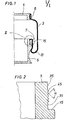
- Fig. 2 eine Einzelheit des Stützkolbens in Fig. 1 nach dem gestrichelten Kreis II ebenfalls im Längsschnitt in vergrößertem Maßstab.
- Der gezeichnete Rollbalg 3 ist in Form eines glattzylindrischen Schlauchkörpers beispielsweise aus synthetischem Kautschuk mit nicht weiter angedeuteten textilen Verstärkungseinlagen ohne Wulste od°r andere Endverdickungen mit über seine ganze Länge gleichbleibender Wandstärke hergestellt. Er dient zum Abfedern des Fahrgestelles eines Straßenkraftfahrzeuges gegen die Radachse und ist zu diesem Zweck mit seinem oberen Endabschnitt an einem mit dem Fahrgestell zusammenhängenden Deckel 4 und mit seinem unteren Endabschnitt an einem auf der . Achse aufsitzenden Stützkolben 5 befestigt, wobei er unter der Wirkung des in seinem Inneren aufgebauten Luftdruckes die gezeichnete Gestalt mit einer nach dem unteren Endabschnitt überleitenden Rollfalte 13 annimmt. Der Stützkolben 5 wiederum bietet mit seinen an den Befestigungsbereich anschließenden Umfangsteilen Anlege- und Abrollflächen für die Rollfalte 13 des Balges. Er steht in ständiger offener Verbindung mit dem Balginnenraum und dient gleichzeitig als Zusatzluftbehälter. Beide Endabschnitte des Rollbalges 3 sind mit Hilfe in sich geschlossener metallischer Spannringe 6, 7 an den zugeordneten tragenden Fahrzeugteilen 4, 5 befestigt.
- Der Stützkolben 5 ist an seinem oberen offenen Ende im Außenumfang zylindrisch so eingezogen, daß er gemäß der Darstellung in Fig. 1 den aufgeschobenen Endabschnitt des Rollbalges 3 zusammen mit dem auf einer flanschartig abgewinkelten ringförmigen Endanschlagfläche 15 aufsitzenden Spannring 7 bis zur vollständigen Ergänzung seines ursprünglichen Durchmessers aufnimmt. Der Spannring 7 bildet infolgedessen eine lückenlos sich anschließende Verlängerung des Stützkolben-Außenmantels.
- Gemäß der Teildarstellung in Fig. 2 ist der eingezogene Befestigungsbereich des Stützkolbens 5 in seinem mittleren Abschnitt mit mehreren - in dem gezeichneten Ausführungsbeispiel fünf - Umfangsrippen 45 vorgesehen. Die Umfangsrippen haben eine gleichseitig-dreieckige Querschnittsform mit einem Außenwinkel α in einer Größenordnung von etwa 90° und schließen mit ihrer diesem Winkel gegenüberliegenden Grundfläche mit den oben und unten benachbarten glattzylindrischen Endabschnitten 35 des Stützkolbens ab. Im Einbauzustand des Rollbalces 3 verformt sich die Balgrwandung unter der Preßkraft des Spannringes 7 in die Zwischenräume zwischen den Umfangsrippen 45 hinein, so daß sich eine formschlüssige Verklammerung des aufgeschobenen Balgendabschnittes ergibt.
Claims (5)
Priority Applications (1)
| Application Number | Priority Date | Filing Date | Title |
|---|---|---|---|
| AT84112611T ATE43419T1 (de) | 1983-12-21 | 1984-10-19 | Luftfederung insbesondere fuer strassenfahrzeuge. |
Applications Claiming Priority (2)
| Application Number | Priority Date | Filing Date | Title |
|---|---|---|---|
| DE3346108 | 1983-12-21 | ||
| DE19833346108 DE3346108A1 (de) | 1983-12-21 | 1983-12-21 | Luftfederung insbesondere fuer strassenfahrzeuge |
Publications (2)
| Publication Number | Publication Date |
|---|---|
| EP0151696A1 true EP0151696A1 (de) | 1985-08-21 |
| EP0151696B1 EP0151696B1 (de) | 1989-05-24 |
Family
ID=6217504
Family Applications (1)
| Application Number | Title | Priority Date | Filing Date |
|---|---|---|---|
| EP84112611A Expired EP0151696B1 (de) | 1983-12-21 | 1984-10-19 | Luftfederung insbesondere für Strassenfahrzeuge |
Country Status (5)
| Country | Link |
|---|---|
| US (1) | US4657229A (de) |
| EP (1) | EP0151696B1 (de) |
| JP (1) | JPS60157532A (de) |
| AT (1) | ATE43419T1 (de) |
| DE (2) | DE3346108A1 (de) |
Cited By (9)
| Publication number | Priority date | Publication date | Assignee | Title |
|---|---|---|---|---|
| EP0306732A2 (de) * | 1987-09-08 | 1989-03-15 | The Firestone Tire & Rubber Company | Luftfeder mit innenliegendem Dichtungsband und Verfahren zu dessen Einbau |
| DE4133878A1 (de) * | 1991-10-12 | 1993-04-15 | Continental Ag | Luftfeder mit einem schlauchrollbalg aus elastomerem werkstoff |
| EP0548581A1 (de) | 1991-12-21 | 1993-06-30 | Continental Aktiengesellschaft | Luftfeder mit einem wulstlosen Luftfederbalg aus elastomerem Werkstoff |
| EP0718522A1 (de) * | 1994-12-22 | 1996-06-26 | Continental Aktiengesellschaft | Spannringbefestigung für einen Schlauchrollbalg einer Luftfeder |
| EP0942193A3 (de) * | 1998-03-11 | 2000-06-07 | BRIDGESTONE/FIRESTONE, Inc. | Pneumatisches Stellelement mit Rillen |
| DE10354574B3 (de) * | 2003-11-21 | 2005-01-27 | Contitech Luftfedersysteme Gmbh | Luftfeder mit einem wulstlosen Schlauchrollbalg |
| EP1657467A1 (de) * | 2004-11-10 | 2006-05-17 | Zf Friedrichshafen Ag | Luftfeder |
| EP2060832A2 (de) | 2007-11-16 | 2009-05-20 | Continental Aktiengesellschaft | Klemmkontur für ein druckbeaufschlagbares Bauteil und Spannmittel dafür |
| DE102009003822A1 (de) | 2009-04-24 | 2010-10-28 | Continental Aktiengesellschaft | Druckbeaufschlagbarer Bauteilverbund |
Families Citing this family (20)
| Publication number | Priority date | Publication date | Assignee | Title |
|---|---|---|---|---|
| US4860571A (en) * | 1986-09-26 | 1989-08-29 | Kenneth L. Smedberg | Power press with improved cushioning system |
| DE3763957D1 (de) * | 1986-11-10 | 1990-08-30 | Firestone Tire & Rubber Co | Federaufbau fuer matrize. |
| US4736615A (en) * | 1987-01-22 | 1988-04-12 | Kenneth L. Smedberg | Pneumatic press counterbalance |
| US5005808A (en) * | 1987-12-01 | 1991-04-09 | The Goodyear Tire & Rubber Company | Airspring end member and airspring assembly |
| US4899995A (en) * | 1988-12-29 | 1990-02-13 | Bridgestone/Firestone, Inc. | Clamp ring assembly for air spring |
| DE4006480A1 (de) * | 1990-03-02 | 1991-09-05 | Continental Ag | Rollbalg-luftfeder mit einem schlauchrollbalg aus elastomerem werkstoff |
| US5326082A (en) * | 1992-06-10 | 1994-07-05 | Bridgestone/Firestone, Inc. | Self locking, snap mounted attachment device |
| US5748759A (en) * | 1995-04-05 | 1998-05-05 | Carver Corporation | Loud speaker structure |
| EP1171722B1 (de) | 2000-02-17 | 2005-02-23 | Vibracoustic GmbH & Co. KG | Luftfederanordnung |
| DE10050777B4 (de) | 2000-10-13 | 2004-09-30 | Continental Aktiengesellschaft | Luftfeder und Verfahren zur Herstellung einer Luftfeder |
| US6474630B1 (en) | 2001-04-24 | 2002-11-05 | Bfs Diversified Products, Llc | Air spring swage assembly |
| DE10163818B4 (de) * | 2001-12-22 | 2020-08-20 | Contitech Luftfedersysteme Gmbh | Schlauchrollbalg-Feder |
| DE10214349A1 (de) * | 2002-03-28 | 2003-10-09 | Zf Lemfoerder Metallwaren Ag | Dichtungsbelag mit Schnappverbindung |
| US6619635B1 (en) | 2002-04-08 | 2003-09-16 | Bfs Diversified Products, Llc | Air spring clamping assembly |
| DE102004042965B4 (de) * | 2004-09-02 | 2007-05-31 | Zf Friedrichshafen Ag | Kugelgelenk |
| DE102004056517A1 (de) * | 2004-11-24 | 2006-06-01 | Contitech Luftfedersysteme Gmbh | Tiefbettklemmkontur für Schlauchrollbalg-Luftfedern |
| US7325794B2 (en) * | 2005-06-06 | 2008-02-05 | Bfs Diversified Products, Llc | Air spring assembly and method |
| US7404547B2 (en) * | 2005-07-27 | 2008-07-29 | Bfs Diversified Products, Llc | Multi-component end member assembly and air spring assembly including the same |
| US20090278290A1 (en) * | 2008-05-08 | 2009-11-12 | Veyance Technologies, Inc. | Easy-to-install air spring |
| JP5657464B2 (ja) * | 2011-04-27 | 2015-01-21 | 株式会社ブリヂストン | 空気ばね |
Citations (5)
| Publication number | Priority date | Publication date | Assignee | Title |
|---|---|---|---|---|
| US2925265A (en) * | 1958-03-19 | 1960-02-16 | Gates Rubber Co | Pneumatic spring assembly |
| DE2024674A1 (de) * | 1969-04-08 | 1971-12-09 | Schmid, Leopold F., 7000 Stuttgart | Zahnstangenlenkung mit hydraulischer oder pneumatischer Lenkhilfe, insbesondere für Kraftfahrzeuge |
| FR2427922A1 (fr) * | 1978-06-05 | 1980-01-04 | Gen Motors Corp | Suspension a jambe de suspension et ressort pneumatique, notamment pour roue de vehicule |
| GB2044395A (en) * | 1979-03-08 | 1980-10-15 | Goodyear Tire & Rubber | Attaching Diaphragm of Rolling Lobe Airspring |
| DE3246962A1 (de) * | 1982-12-18 | 1984-06-20 | Continental Gummi-Werke Ag, 3000 Hannover | Luftfederung insbesondere fuer strassenfahrzeuge |
Family Cites Families (9)
| Publication number | Priority date | Publication date | Assignee | Title |
|---|---|---|---|---|
| DE1081779B (de) * | 1955-02-16 | 1960-05-12 | Continental Gummi Werke Ag | Torusfoermiger Hohlkoerper aus Gummi fuer Luftfederungen, insbesondere an Fahrzeugen |
| US3022152A (en) * | 1957-10-15 | 1962-02-20 | Phillips Petroleum Co | Method of killing plants |
| NL129255C (de) * | 1964-03-11 | Michelin & Cie | ||
| US3819166A (en) * | 1972-10-12 | 1974-06-25 | Gen Motors Corp | Gas bladder for combination liquid gas suspension device |
| US3850437A (en) * | 1972-11-17 | 1974-11-26 | Gen Motors Corp | Leveling system with a single offset mounted air spring |
| US3897941A (en) * | 1974-03-28 | 1975-08-05 | Goodyear Tire & Rubber | Reinforced fluid spring |
| US4378935A (en) * | 1979-03-08 | 1983-04-05 | The Goodyear Tire & Rubber Company | Rolling lobe airspring |
| US4398704A (en) * | 1979-07-16 | 1983-08-16 | General Motors Corporation | Vehicle pneumatic suspension system with dead band adjustment |
| IT1139569B (it) * | 1981-10-27 | 1986-09-24 | Gomma Antivibranti Applic | Molla ad aria |
-
1983
- 1983-12-21 DE DE19833346108 patent/DE3346108A1/de not_active Withdrawn
-
1984
- 1984-10-19 DE DE8484112611T patent/DE3478335D1/de not_active Expired
- 1984-10-19 EP EP84112611A patent/EP0151696B1/de not_active Expired
- 1984-10-19 AT AT84112611T patent/ATE43419T1/de not_active IP Right Cessation
- 1984-12-21 JP JP59268730A patent/JPS60157532A/ja active Pending
- 1984-12-21 US US06/684,486 patent/US4657229A/en not_active Expired - Fee Related
Patent Citations (5)
| Publication number | Priority date | Publication date | Assignee | Title |
|---|---|---|---|---|
| US2925265A (en) * | 1958-03-19 | 1960-02-16 | Gates Rubber Co | Pneumatic spring assembly |
| DE2024674A1 (de) * | 1969-04-08 | 1971-12-09 | Schmid, Leopold F., 7000 Stuttgart | Zahnstangenlenkung mit hydraulischer oder pneumatischer Lenkhilfe, insbesondere für Kraftfahrzeuge |
| FR2427922A1 (fr) * | 1978-06-05 | 1980-01-04 | Gen Motors Corp | Suspension a jambe de suspension et ressort pneumatique, notamment pour roue de vehicule |
| GB2044395A (en) * | 1979-03-08 | 1980-10-15 | Goodyear Tire & Rubber | Attaching Diaphragm of Rolling Lobe Airspring |
| DE3246962A1 (de) * | 1982-12-18 | 1984-06-20 | Continental Gummi-Werke Ag, 3000 Hannover | Luftfederung insbesondere fuer strassenfahrzeuge |
Cited By (15)
| Publication number | Priority date | Publication date | Assignee | Title |
|---|---|---|---|---|
| EP0306732A2 (de) * | 1987-09-08 | 1989-03-15 | The Firestone Tire & Rubber Company | Luftfeder mit innenliegendem Dichtungsband und Verfahren zu dessen Einbau |
| EP0306732A3 (en) * | 1987-09-08 | 1990-01-17 | The Firestone Tire & Rubber Company | Air spring having internal sealing band and method of installing same |
| US5267725A (en) * | 1991-10-12 | 1993-12-07 | Continental Aktiengesellschaft | Air spring having a sleeve-type flexible member made of elastomeric material |
| EP0537604A1 (de) * | 1991-10-12 | 1993-04-21 | Continental Aktiengesellschaft | Luftfeder mit einem Schlauchrollbalg aus elastomerem Werkstoff |
| DE4133878A1 (de) * | 1991-10-12 | 1993-04-15 | Continental Ag | Luftfeder mit einem schlauchrollbalg aus elastomerem werkstoff |
| EP0548581A1 (de) | 1991-12-21 | 1993-06-30 | Continental Aktiengesellschaft | Luftfeder mit einem wulstlosen Luftfederbalg aus elastomerem Werkstoff |
| DE4142561A1 (de) * | 1991-12-21 | 1993-07-01 | Continental Ag | Luftfeder mit einem wulstlosen luftfederbalg aus elastomerem werkstoff |
| EP0718522A1 (de) * | 1994-12-22 | 1996-06-26 | Continental Aktiengesellschaft | Spannringbefestigung für einen Schlauchrollbalg einer Luftfeder |
| EP0942193A3 (de) * | 1998-03-11 | 2000-06-07 | BRIDGESTONE/FIRESTONE, Inc. | Pneumatisches Stellelement mit Rillen |
| DE10354574B3 (de) * | 2003-11-21 | 2005-01-27 | Contitech Luftfedersysteme Gmbh | Luftfeder mit einem wulstlosen Schlauchrollbalg |
| EP1657467A1 (de) * | 2004-11-10 | 2006-05-17 | Zf Friedrichshafen Ag | Luftfeder |
| EP2060832A2 (de) | 2007-11-16 | 2009-05-20 | Continental Aktiengesellschaft | Klemmkontur für ein druckbeaufschlagbares Bauteil und Spannmittel dafür |
| DE102007055077A1 (de) | 2007-11-16 | 2009-05-20 | Continental Aktiengesellschaft | Klemmkontur für ein druckbeaufschlagbares Bauteil und Spannmittel dafür |
| EP2060832B1 (de) | 2007-11-16 | 2015-09-16 | Continental Teves AG & Co. oHG | Klemmkontur für ein druckbeaufschlagbares Bauteil und Spannmittel dafür |
| DE102009003822A1 (de) | 2009-04-24 | 2010-10-28 | Continental Aktiengesellschaft | Druckbeaufschlagbarer Bauteilverbund |
Also Published As
| Publication number | Publication date |
|---|---|
| EP0151696B1 (de) | 1989-05-24 |
| ATE43419T1 (de) | 1989-06-15 |
| DE3478335D1 (en) | 1989-06-29 |
| DE3346108A1 (de) | 1985-07-04 |
| US4657229A (en) | 1987-04-14 |
| JPS60157532A (ja) | 1985-08-17 |
Similar Documents
| Publication | Publication Date | Title |
|---|---|---|
| EP0151696A1 (de) | Luftfederung insbesondere für Strassenfahrzeuge | |
| DE2061625C3 (de) | Zwischenlager für die Gelenkwelle von Kraftfahrzeugen | |
| DE102007034362A1 (de) | Luftfeder | |
| DE2816742C2 (de) | ||
| EP3408556B1 (de) | Luftfeder mit faltenbalg | |
| EP1140529B1 (de) | Fahrzeug-achsaufhängung | |
| DE4009495A1 (de) | Rollbalg-luftfeder mit einem verstaerkten rollbalg | |
| DE3318060C2 (de) | ||
| DE60103099T2 (de) | Abgedichtetes Axialwälzlager für Fahrzeugaufhängung | |
| WO2013167390A1 (de) | Luftfeder und verfahren zum umschlagen eines luftfederbalges einer luftfeder | |
| DE3111566A1 (de) | Luftreifenanordnung | |
| DE10163818B4 (de) | Schlauchrollbalg-Feder | |
| DE69915404T2 (de) | Thermoplastische, elastomere Gasfeder | |
| DE2842555C2 (de) | ||
| EP2090801B1 (de) | Luftfeder-Rollbalg | |
| DE3007858C2 (de) | ||
| DE3246962C2 (de) | ||
| DE19645228C2 (de) | Luftfeder mit Abrollkörper | |
| DE3017733A1 (de) | Rollbalg fuer fahrzeug-luftfederungen | |
| EP0212333A2 (de) | Fahrzeugrad | |
| DE4402296A1 (de) | Bereiftes Fahrzeugrad | |
| DE4438931C2 (de) | Hydrolager | |
| DE102004015602B4 (de) | Luftfedereinrichtung | |
| DE2223200B2 (de) | Laufrad mit wenigstens einem Laufreifen, einer Felge, einer Nabe und zwei gegeneinander gestellten Konuslagern | |
| DE102011109670B4 (de) | Luftfeder |
Legal Events
| Date | Code | Title | Description |
|---|---|---|---|
| PUAI | Public reference made under article 153(3) epc to a published international application that has entered the european phase |
Free format text: ORIGINAL CODE: 0009012 |
|
| AK | Designated contracting states |
Designated state(s): AT BE CH DE FR GB IT LI LU NL SE |
|
| 17P | Request for examination filed |
Effective date: 19860418 |
|
| 17Q | First examination report despatched |
Effective date: 19870513 |
|
| RAP1 | Party data changed (applicant data changed or rights of an application transferred) |
Owner name: CONTINENTAL AKTIENGESELLSCHAFT |
|
| GRAA | (expected) grant |
Free format text: ORIGINAL CODE: 0009210 |
|
| AK | Designated contracting states |
Kind code of ref document: B1 Designated state(s): AT BE CH DE FR GB IT LI LU NL SE |
|
| PG25 | Lapsed in a contracting state [announced via postgrant information from national office to epo] |
Ref country code: NL Effective date: 19890524 Ref country code: BE Effective date: 19890524 |
|
| REF | Corresponds to: |
Ref document number: 43419 Country of ref document: AT Date of ref document: 19890615 Kind code of ref document: T |
|
| REF | Corresponds to: |
Ref document number: 3478335 Country of ref document: DE Date of ref document: 19890629 |
|
| ITF | It: translation for a ep patent filed |
Owner name: ING. C. GREGORJ S.P.A. |
|
| ET | Fr: translation filed | ||
| GBT | Gb: translation of ep patent filed (gb section 77(6)(a)/1977) | ||
| NLV1 | Nl: lapsed or annulled due to failure to fulfill the requirements of art. 29p and 29m of the patents act | ||
| PG25 | Lapsed in a contracting state [announced via postgrant information from national office to epo] |
Ref country code: AT Effective date: 19891019 |
|
| PG25 | Lapsed in a contracting state [announced via postgrant information from national office to epo] |
Ref country code: LU Free format text: LAPSE BECAUSE OF NON-PAYMENT OF DUE FEES Effective date: 19891031 Ref country code: LI Effective date: 19891031 Ref country code: CH Effective date: 19891031 |
|
| PLBE | No opposition filed within time limit |
Free format text: ORIGINAL CODE: 0009261 |
|
| STAA | Information on the status of an ep patent application or granted ep patent |
Free format text: STATUS: NO OPPOSITION FILED WITHIN TIME LIMIT |
|
| 26N | No opposition filed | ||
| REG | Reference to a national code |
Ref country code: CH Ref legal event code: PL |
|
| ITTA | It: last paid annual fee | ||
| EAL | Se: european patent in force in sweden |
Ref document number: 84112611.3 |
|
| REG | Reference to a national code |
Ref country code: GB Ref legal event code: IF02 |
|
| PGFP | Annual fee paid to national office [announced via postgrant information from national office to epo] |
Ref country code: GB Payment date: 20030929 Year of fee payment: 20 |
|
| PGFP | Annual fee paid to national office [announced via postgrant information from national office to epo] |
Ref country code: SE Payment date: 20031001 Year of fee payment: 20 |
|
| PGFP | Annual fee paid to national office [announced via postgrant information from national office to epo] |
Ref country code: DE Payment date: 20031002 Year of fee payment: 20 |
|
| PGFP | Annual fee paid to national office [announced via postgrant information from national office to epo] |
Ref country code: FR Payment date: 20031009 Year of fee payment: 20 |
|
| PG25 | Lapsed in a contracting state [announced via postgrant information from national office to epo] |
Ref country code: GB Free format text: LAPSE BECAUSE OF EXPIRATION OF PROTECTION Effective date: 20041018 |
|
| REG | Reference to a national code |
Ref country code: GB Ref legal event code: PE20 |
|
| EUG | Se: european patent has lapsed |