EP0150257A2 - Roof, in particular for a building, and method for its manufacture - Google Patents
Roof, in particular for a building, and method for its manufacture Download PDFInfo
- Publication number
- EP0150257A2 EP0150257A2 EP84109591A EP84109591A EP0150257A2 EP 0150257 A2 EP0150257 A2 EP 0150257A2 EP 84109591 A EP84109591 A EP 84109591A EP 84109591 A EP84109591 A EP 84109591A EP 0150257 A2 EP0150257 A2 EP 0150257A2
- Authority
- EP
- European Patent Office
- Prior art keywords
- roof
- cover
- welding
- sheets
- fix
- Prior art date
- Legal status (The legal status is an assumption and is not a legal conclusion. Google has not performed a legal analysis and makes no representation as to the accuracy of the status listed.)
- Granted
Links
Images


Classifications
-
- E—FIXED CONSTRUCTIONS
- E04—BUILDING
- E04D—ROOF COVERINGS; SKY-LIGHTS; GUTTERS; ROOF-WORKING TOOLS
- E04D3/00—Roof covering by making use of flat or curved slabs or stiff sheets
- E04D3/24—Roof covering by making use of flat or curved slabs or stiff sheets with special cross-section, e.g. with corrugations on both sides, with ribs, flanges, or the like
- E04D3/30—Roof covering by making use of flat or curved slabs or stiff sheets with special cross-section, e.g. with corrugations on both sides, with ribs, flanges, or the like of metal
-
- E—FIXED CONSTRUCTIONS
- E04—BUILDING
- E04D—ROOF COVERINGS; SKY-LIGHTS; GUTTERS; ROOF-WORKING TOOLS
- E04D13/00—Special arrangements or devices in connection with roof coverings; Protection against birds; Roof drainage; Sky-lights
- E04D13/10—Snow traps ; Removing snow from roofs; Snow melters
Definitions
- the present invention relates to a roof, particularly for a building, consisting essentially of an attic, comprising at least sand purlins, and of a covering resting on the attic, as well as to a method of manufacturing said roof. .
- this roof is characterized in that the cover consists of a single piece of monobloc structure, consisting of flat sheets of light alloy, joined by welding and folded according to the shape of the roof.
- the cover consists of a single piece of monobloc structure, consisting of flat sheets of light alloy, joined by welding and folded according to the shape of the roof.
- One of the variants proposed according to the invention provides gutters made of identical sheets and their total integration into said cover.
- the basic principle of the invention is the prefabrication of the exterior covering of a roof and, for this purpose, the use of flat sheets of aluminum alloy with a thickness of a few mm. These sheets are joined by welding in a monobloc structure and folded at the location of the ridge and the gutters.
- the workshops specializing in sheet metal fabrication have bending cylinders up to 12 m wide.
- the prefabricated roofing in the workshop is then transported by crane, truck and / or helicopter to the place of construction, where it is placed and fixed directly to the roof of the building. Any openings for chimneys or other elements can be easily executed in the workshop or even on site.
- the monobloc cover is self-supporting and can be installed and fixed simply on sand purlins, for example.
- the process provides for the transport of two or more sufficiently small parts and their final junction by welding to the final location. .
- Appropriate aluminum alloy sheets are available at very competitive prices.
- the company "Aluminum Suisse SA” for example offers “ridged aluminum sheets” under the brand name “Anticorodal 110 A 6110/41” in thicknesses from 2 to 9 mm and rectangular dimensions of 2.5 m x 8.0 m. These sheets have a structured and colored surface according to the customer's wishes and they allow welding and bending operations.
- the roof according to Fig. 3 essentially comprises an attic in conventional framework and an external cover 12 of one-piece aluminum alloy structure with a thickness of a few mm, to which are welded, by means of supports 22, rings 15 and 21 for mooring and / or for snow hose (Fig. 1 and Fig. 15).
- the cover 12 is provided with holes 20 (Fig. 14) used for its attachment to the rafters 8 of the roof. These holes 20 have a diameter of about 10 mm and are placed along the rafters 8 at spaces between 0.5 m and 1 m; they are intended to receive bolts 11 with a length of approximately 120 mm. If the surface structure of the cover 12 requires it, each hole 20 is surrounded by a recess by milling 19; a seal 18 placed between the head of each bolt 11 and the cover 12 serves to guarantee an absolute seal.
- the gutters are an integral part of the cover 12 (Fig. 8 and Fig. 9).
- the gutter 9 is made of the same sheet as the cover 12; it is formed by a folding operation at the edge of the cover 12. At the site, all that is left is to connect the downspouts.
- the roof of the roof according to Fig. 8 and Fig. 10 is constructed in a conventional manner. Pits purlins 2 and a ridge purlins 16 are placed on the exterior walls 1 of the building. Chevrons 8 resting on purlins 2 and 16 carry the cover 12. The surface of each chevron 8 directly touching the cover 12 is provided with ventilation recesses 10 (Fig. 8 and Fig. 11) of a width x corresponding approximately at the width x 'of the rafters 8. Line 13 indicates the ventilation current along the rafters 8. The spacing of these recesses 10 is equal to the spacing of the fixing bolts 11. Elements 3, 4, 5, 6 and 7 according to FIG. 8 are used for insulation and finishing of the roof and are not the subject of the present invention.
- Fig. 9 shows a sloping roof without eaves. The details of this construction are similar to those of the embodiment described above in connection with FIG. 8 and Fig. 10. Finally, Fig. 12 and Fig. 13 show some details of the construction of a flat roof, with and without eaves respectively.
- the reference signs designate elements similar to those of the pitched roof according to FIG. 8.
Abstract
Description
La présente invention se rapporte à une toiture, particulièrement pour un bâtiment, se composant essentiellement d'un comble, comprenant au moins des pannes sablières, et d'une couverture reposant sur le comble, ainsi qu'à un procédé de fabrication de ladite toiture.The present invention relates to a roof, particularly for a building, consisting essentially of an attic, comprising at least sand purlins, and of a covering resting on the attic, as well as to a method of manufacturing said roof. .
L'art de la construction des toitures pour des bâtiments connaît une très longue tradition et a atteint ces dernières années une extrème perfection, aussi bien pour des toits en pente que pour des toits plats. Des millions d'exemplaires de toits sont répandus dans le monde entier et il ne paraît donc pas nécessaire de décrire ici en détail les différentes techniques connues à ce jour.The art of roofing construction for buildings has a very long tradition and has reached extreme perfection in recent years, both for pitched roofs and for flat roofs. Millions of roofs are sold all over the world and it therefore does not seem necessary to describe here in detail the various techniques known to date.
On constate cependent que ces toitures connues jusqu'à présent ne remplissent pas simultanément les diverses exigences stipulées, à savoir par exemple une très haute résistance aux intempéries (chaleur, froid, humidité, pluie, grêle, tempête, glace, pression des neiges, etc.) et une longue durée de vie d'une part, et de très modestes coûts de construction et d'entretien d'autre part.We note however that these roofs known until now do not simultaneously fulfill the various stipulated requirements, namely for example a very high resistance to bad weather (heat, cold, humidity, rain, hail, storm, ice, snow pressure, etc. .) and a long service life on the one hand, and very modest construction and maintenance costs on the other.
Il est donc le but de la présente invention de créer une toiture qui réunit simultanément toutes les qualitées précitées et permettant en plus de raccourcir considérablement la durée de construction. Selon l'invention cette toiture est caractérisée en ce que la couverture consiste en une seule pièce de structure monobloc, se composant de tôles plates en alliage léger, jointes par soudage et pliées selon la forme de la toiture. Une des variantes proposées selon l'invention prévoit des gouttières faites de tôles identiques et leurs intégration totale dans ladite couverture. Le principe de base de l'invention est la préfabrication de la couverture extérieure d'un toit et, dans ce but, l'utilisation de tôles plates en alliage d'aluminium d'une épaisseur de quelques mm. Ces tôles sont jointes par soudage en structure monobloc et pliées à l'endroit du faîte et des gouttières. Les ateliers spécialisés dans le façonnage des tôles disposent de cylindres à cintrer d'une largeur jusqu'à 12 m. La couverture préfabriquée en atelier est ensuite transportée par grue, camion et/ou hélicoptère à l'endroit de la construction, où elle est posée et fixée directement sur le comble du bâtiment. D'éventuels orifices pour cheminées ou autres éléments peuvent être exécutés aisément en atelier voir sur place.It is therefore the aim of the present invention to create a roof which simultaneously combines all the aforementioned qualities and also makes it possible to considerably shorten the construction time. According to the invention, this roof is characterized in that the cover consists of a single piece of monobloc structure, consisting of flat sheets of light alloy, joined by welding and folded according to the shape of the roof. One of the variants proposed according to the invention provides gutters made of identical sheets and their total integration into said cover. The basic principle of the invention is the prefabrication of the exterior covering of a roof and, for this purpose, the use of flat sheets of aluminum alloy with a thickness of a few mm. These sheets are joined by welding in a monobloc structure and folded at the location of the ridge and the gutters. The workshops specializing in sheet metal fabrication have bending cylinders up to 12 m wide. The prefabricated roofing in the workshop is then transported by crane, truck and / or helicopter to the place of construction, where it is placed and fixed directly to the roof of the building. Any openings for chimneys or other elements can be easily executed in the workshop or even on site.
Pour des toitures relativement petites on peut renoncer à la construction d'un véritable comble en charpente; la couverture monobloc est autoportante et peut être posée et fixée simplement sur des pannes sablières, par exemple.For relatively small roofs we can do without the construction of a real roof structure; the monobloc cover is self-supporting and can be installed and fixed simply on sand purlins, for example.
Si les dimensions de la toiture et/ou les moyens de maniement et de transport disponibles ne permettent pas la préfabrication de la couverture entière, le procédé prévoit le transport de deux ou plusieurs parties suffisamment petites et leur jonction finale par soudage à l'emplacement définitif.If the dimensions of the roof and / or the available handling and transport means do not allow the prefabrication of the entire roof, the process provides for the transport of two or more sufficiently small parts and their final junction by welding to the final location. .
Des tôles appropriées en alliage d'aluminium sont en vente à des prix très compétitifs. La maison "Aluminium Suisse SA" par exemple offre des "tôles striées en aluminium" sous la marque "Anticorodal 110 A 6110/41" à des épaisseurs de 2 à 9 mm et des dimensions rectangulaires de 2,5 m x 8,0 m. Ces tôles ont une surface structurée et colorée selon le désir du client et elles permettent des opérations de soudage et de pliage.Appropriate aluminum alloy sheets are available at very competitive prices. The company "Aluminum Suisse SA" for example offers "ridged aluminum sheets" under the brand name "Anticorodal 110 A 6110/41" in thicknesses from 2 to 9 mm and rectangular dimensions of 2.5 m x 8.0 m. These sheets have a structured and colored surface according to the customer's wishes and they allow welding and bending operations.
La toiture selon l'invention sera décrite ci-après plus en détail à l'aide d'exemples d'exécution schématisés dans les dessins annexés; on reconnaît dans la
- Fig. 1 la section d'une partie de la couverture du toit selon l'invention, avec anneau pour tuyau pare-neige;
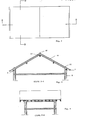
- Fig. 2 le plan d'un toit à deux pans;
- Fig. 3 la coupe A-A selon Fig. 2;
- Fig. 4 la coupe B-B selon Fig. 2;
- Fig. 5 le plan horizontal et transversal d'un toit à deux pans;
- Fig. 6 le plan horizontal et transversal d'un toit à un pan;
- Fig. 7 le plan horizontal et transversal d'un toit plat;
- Fig. 8 un détail de la coupe selon Fig. 3;
- Fig. 9 un détail d'une variante sans avant-toit;
- Fig. 10 un détail du faîte selon Fig. 3;
- Fig. 11 une vue sur deux chevrons avec des détails pour la ventilation et la fixation de la couverture;
- Fig. 12 une coupe de la rive d'un toit plat;
- Fig. 13 une variante sans avant-toit;
- Fig. 14 la fixation de la tôle sur un chevron; et
- Fig. 15 un détail du pliage de la tôle au faîte, avec anneau d'amarrage.
- Fig. 1 the section of a part of the roof covering according to the invention, with a ring for snow barrier pipe;
- Fig. 2 the plan of a gable roof;
- Fig. 3 the section AA according to FIG. 2;
- Fig. 4 the section BB according to FIG. 2;
- Fig. 5 the horizontal and transverse plane of a hipped roof;
- Fig. 6 the horizontal and transverse plane of a roof with a pan;
- Fig. 7 the horizontal and transverse plane of a flat roof;
- Fig. 8 a detail of the section according to FIG. 3;
- Fig. 9 a detail of a variant without eaves;
- Fig. 10 a detail of the ridge according to FIG. 3;
- Fig. 11 a view of two rafters with details for ventilation and fixing the cover;
- Fig. 12 a section of the bank of a flat roof;
- Fig. 13 a variant without eaves;
- F ig. 14 fixing the sheet to a rafter; and
- Fig. 15 a detail of the folding of the sheet to the ridge, with mooring ring.
La toiture selon Fig. 3 comprend essentiellement un comble en charpente conventionnelle et une couverture extérieure 12 de structure monobloc en alliage d'aluminium d'une épaisseur de quelques mm, à laquelle sont soudés, par l'intermédiaire de supports 22, des anneaux 15 et 21 d'amarrage et/ou pour tuyau pare-neige (Fig. 1 et Fig. 15).The roof according to Fig. 3 essentially comprises an attic in conventional framework and an
D'autre part la couverture 12 est munie de trous 20 (Fig. 14) servant à sa fixation sur les chevrons 8 du comble. Ces trous 20 ont un diamètre d'environ 10 mm et sont placés le long des chevrons 8 à des espaces entre 0,5 m et 1 m; ils sont destinés à recevoir des boulons 11 d'une longueur de 120 mm environ. Si la structure superficielle de la couverture 12 l'exige, chaque trou 20 est entouré d'une enfonçure par fraisage 19; un joint 18 placé entre la tête de chaque boulon 11 et la couverture 12 sert à garantir une étanchéité absolue.On the other hand the
Selon une exécution particulière de l'invention les gouttières font partie intégrante de la couverture 12 (Fig. 8 et Fig. 9). Dans ces exemples, la gouttière 9 est faite de la même tôle que la couverture 12; elle est formée par une opération de pliage en bordure de la couverture 12. Au chantier, il n'y a plus qu'à raccorder les descentes d'eau.According to a particular embodiment of the invention the gutters are an integral part of the cover 12 (Fig. 8 and Fig. 9). In these examples, the
Le comble de la toiture selon Fig. 8 et Fig. 10 est construit d'une façon conventionnelle. Des pannes sablières 2 et une panne faîtière 16 sont posées sur les mûrs extérieurs 1 du bâtiment. Des chevrons 8 reposant sur les pannes 2 et 16 portent la couverture 12. La surface de chaque chevron 8 touchant directement la couverture 12 est munie d'évidements d'aération 10 (Fig. 8 et Fig. 11) d'une largeur x correspondant approximativement à la largeur x' des chevrons 8. La ligne 13 indique le courant d'aération le long des chevrons 8. L'espacement de ces évidements 10 est égale à l'espacement des boulons 11 de fixation. Les éléments 3, 4, 5 ,6 et 7 selon Fig. 8 servent à l'isolation et à la finition du toit et ne font pas l'objet de la présente invention.The roof of the roof according to Fig. 8 and Fig. 10 is constructed in a conventional manner.
Fig. 9 montre une toiture en pente sans avant-toit. Les détails de cette construction sont similaires à ceux de l'exécution décrite ci-dessus en rapport avec Fig. 8 et Fig. 10. Finalement, Fig. 12 et Fig. 13 montrent quelques détails de la construction d'une toiture plate, avec et sans avant-toit respectivement. Les signes de référence désignent des éléments similaires à ceux du toit en pente selon Fig. 8.Fig. 9 shows a sloping roof without eaves. The details of this construction are similar to those of the embodiment described above in connection with FIG. 8 and Fig. 10. Finally, Fig. 12 and Fig. 13 show some details of the construction of a flat roof, with and without eaves respectively. The reference signs designate elements similar to those of the pitched roof according to FIG. 8.
Les avantages le la toiture selon la présente invention par rapport aux toitures connues sont considérables:
- - résistance absolue aux intempéries;
- - poid inférieur;
- - durée de vie illimitée;
- - temps de montage très bref;
- - couverture non-inflammable et sans entretien;
- - coûts de construction bien inférieurs:
- - absolute weather resistance;
- - lower weight;
- - unlimited lifespan;
- - very short assembly time;
- - non-flammable and maintenance-free cover;
- - much lower construction costs:
Le prix par m2 des "tôles striées en aluminium" d'une épaisseur appropriée de par exemple "3mm/5mm" s'élève environ à un dixième du prix de tuiles ou d'autres éléments comparables. Par conséquent, et si l'on tient compte des économies dues à la suppression des travaux de lattage et de ferblanterie, le coût total d'une toiture selon l'invention sera toujours nettement inférieur, même avec un éventuel transport coûteux en hélicoptère.The price per m 2 of "aluminum ribbed sheets" with an appropriate thickness of, for example, "3mm / 5mm" is approximately one tenth of the price of tiles or other comparable elements. Consequently, and if one takes into account the savings due to the elimination of battening and tinsmithing works, the total cost of a roof according to the invention will always be much lower, even with possible expensive transport by helicopter.
Claims (7)
Priority Applications (1)
| Application Number | Priority Date | Filing Date | Title |
|---|---|---|---|
| AT84109591T ATE35837T1 (en) | 1984-02-02 | 1984-08-11 | ROOF, PARTICULARLY FOR A BUILDING AND PROCESS FOR ITS MANUFACTURE. |
Applications Claiming Priority (2)
| Application Number | Priority Date | Filing Date | Title |
|---|---|---|---|
| CH499/84 | 1984-02-02 | ||
| CH49984A CH646486A5 (en) | 1984-02-02 | 1984-02-02 | ROOFING, PARTICULARLY FOR A BUILDING, AND METHOD FOR ITS MANUFACTURE. |
Publications (3)
| Publication Number | Publication Date |
|---|---|
| EP0150257A2 true EP0150257A2 (en) | 1985-08-07 |
| EP0150257A3 EP0150257A3 (en) | 1986-08-13 |
| EP0150257B1 EP0150257B1 (en) | 1988-07-20 |
Family
ID=4188403
Family Applications (1)
| Application Number | Title | Priority Date | Filing Date |
|---|---|---|---|
| EP84109591A Expired EP0150257B1 (en) | 1984-02-02 | 1984-08-11 | Roof, in particular for a building, and method for its manufacture |
Country Status (4)
| Country | Link |
|---|---|
| EP (1) | EP0150257B1 (en) |
| AT (1) | ATE35837T1 (en) |
| CH (1) | CH646486A5 (en) |
| DE (1) | DE3472811D1 (en) |
Families Citing this family (1)
| Publication number | Priority date | Publication date | Assignee | Title |
|---|---|---|---|---|
| DE4316437A1 (en) * | 1992-11-14 | 1994-05-19 | Braas Gmbh | Sheet-metal cover strip - incorporating narrow longitudinal regions with lower strength and higher breaking strain than the rest of the strip |
Citations (7)
| Publication number | Priority date | Publication date | Assignee | Title |
|---|---|---|---|---|
| GB420974A (en) * | 1933-05-12 | 1934-12-12 | Evelyn Hurden | Improvements in or relating to the construction of sectional buildings |
| US2356768A (en) * | 1942-06-22 | 1944-08-29 | Masonite Corp | Building construction |
| FR985574A (en) * | 1949-02-24 | 1951-07-20 | Bristol Aeroplane Company Hous | Construction in prefabricated elements |
| FR1259629A (en) * | 1960-05-11 | 1961-04-28 | Improvements to building roofs | |
| FR93109E (en) * | 1966-07-23 | 1969-02-14 | Jean Secail | Roof prefabricated in ceramic elements. |
| FR2059159A5 (en) * | 1969-08-25 | 1971-05-28 | Dewitte Rafael | Plastic roofing tiles and components |
| FR2225594A1 (en) * | 1973-04-12 | 1974-11-08 | Comble Roland | Light self-supporting roof structure for buildings - - made of glass fibre and resin on a metal, reinforced frame |
Family Cites Families (2)
| Publication number | Priority date | Publication date | Assignee | Title |
|---|---|---|---|---|
| BE781024A (en) * | 1972-03-22 | 1972-07-17 | Deckers Edwin | SUPPORTED WALL, SUCH AS FOR EXAMPLE A ROOF. |
| BE888357A (en) * | 1981-04-10 | 1981-10-12 | Verraes Wolfgang P J | ROOF CONSTRUCTION, |
-
1984
- 1984-02-02 CH CH49984A patent/CH646486A5/en not_active IP Right Cessation
- 1984-08-11 DE DE8484109591T patent/DE3472811D1/en not_active Expired
- 1984-08-11 AT AT84109591T patent/ATE35837T1/en not_active IP Right Cessation
- 1984-08-11 EP EP84109591A patent/EP0150257B1/en not_active Expired
Patent Citations (7)
| Publication number | Priority date | Publication date | Assignee | Title |
|---|---|---|---|---|
| GB420974A (en) * | 1933-05-12 | 1934-12-12 | Evelyn Hurden | Improvements in or relating to the construction of sectional buildings |
| US2356768A (en) * | 1942-06-22 | 1944-08-29 | Masonite Corp | Building construction |
| FR985574A (en) * | 1949-02-24 | 1951-07-20 | Bristol Aeroplane Company Hous | Construction in prefabricated elements |
| FR1259629A (en) * | 1960-05-11 | 1961-04-28 | Improvements to building roofs | |
| FR93109E (en) * | 1966-07-23 | 1969-02-14 | Jean Secail | Roof prefabricated in ceramic elements. |
| FR2059159A5 (en) * | 1969-08-25 | 1971-05-28 | Dewitte Rafael | Plastic roofing tiles and components |
| FR2225594A1 (en) * | 1973-04-12 | 1974-11-08 | Comble Roland | Light self-supporting roof structure for buildings - - made of glass fibre and resin on a metal, reinforced frame |
Also Published As
| Publication number | Publication date |
|---|---|
| DE3472811D1 (en) | 1988-08-25 |
| EP0150257A3 (en) | 1986-08-13 |
| ATE35837T1 (en) | 1988-08-15 |
| EP0150257B1 (en) | 1988-07-20 |
| CH646486A5 (en) | 1984-11-30 |
Similar Documents
| Publication | Publication Date | Title |
|---|---|---|
| US5301474A (en) | Roofing system for potable water | |
| US5295338A (en) | Building panel assembly | |
| EP0150257B1 (en) | Roof, in particular for a building, and method for its manufacture | |
| FR2961235A1 (en) | DEVICE AND METHOD FOR THE INTEGRATED INSTALLATION OF SOLAR PANELS, PARTICULARLY PHOTOVOLTAIC, ON THE ROOF OF A BUILDING | |
| KR20200002231U (en) | Seaming structure of roof panel | |
| JPH11117479A (en) | Fitting structure for solar battery module | |
| JPH086408B2 (en) | Independent component for roofing | |
| JPS6011212Y2 (en) | Glass plate support device for skylights | |
| JPH0636137Y2 (en) | Roof panel connection structure | |
| KR880004208Y1 (en) | Prefabricated pannel | |
| JP2781955B2 (en) | Internally-connected vertical roof | |
| US4145851A (en) | Structural enclosure | |
| US2126574A (en) | Structural glass | |
| RU39621U1 (en) | ROOF | |
| JP2736951B2 (en) | Roof structure | |
| KR20070031526A (en) | Construction method of roof and roof system for apartment building | |
| JPH0411991Y2 (en) | ||
| JP2603412Y2 (en) | Exterior corridor drainage structure | |
| FR2497858A1 (en) | SUPPORTING ELEMENT FOR THE CONSTRUCTION OF CEILINGS OR ROOFS | |
| JP3412812B2 (en) | Exterior panel structure | |
| JP2500055B2 (en) | Roof material connection structure | |
| CN113062506A (en) | Construction method for capping parapet wall and ceramic plate curtain wall | |
| JP2526968Y2 (en) | Snow-free roof structure | |
| FR2520414A1 (en) | Prefabricated triangulated roofing section - is in one piece of lightweight reinforced concrete of full or half roof width in length | |
| JP3349492B2 (en) | Mounting structure of building exterior material, mounting member, and building exterior structure |
Legal Events
| Date | Code | Title | Description |
|---|---|---|---|
| PUAI | Public reference made under article 153(3) epc to a published international application that has entered the european phase |
Free format text: ORIGINAL CODE: 0009012 |
|
| 17P | Request for examination filed |
Effective date: 19850218 |
|
| AK | Designated contracting states |
Designated state(s): AT BE CH DE FR GB IT LI LU NL SE |
|
| PUAL | Search report despatched |
Free format text: ORIGINAL CODE: 0009013 |
|
| AK | Designated contracting states |
Kind code of ref document: A3 Designated state(s): AT BE CH DE FR GB IT LI LU NL SE |
|
| 17Q | First examination report despatched |
Effective date: 19880212 |
|
| GRAA | (expected) grant |
Free format text: ORIGINAL CODE: 0009210 |
|
| AK | Designated contracting states |
Kind code of ref document: B1 Designated state(s): AT BE CH DE FR GB IT LI LU NL SE |
|
| PG25 | Lapsed in a contracting state [announced via postgrant information from national office to epo] |
Ref country code: SE Effective date: 19880720 Ref country code: NL Effective date: 19880720 Ref country code: IT Free format text: LAPSE BECAUSE OF FAILURE TO SUBMIT A TRANSLATION OF THE DESCRIPTION OR TO PAY THE FEE WITHIN THE PRESCRIBED TIME-LIMIT;WARNING: LAPSES OF ITALIAN PATENTS WITH EFFECTIVE DATE BEFORE 2007 MAY HAVE OCCURRED AT ANY TIME BEFORE 2007. THE CORRECT EFFECTIVE DATE MAY BE DIFFERENT FROM THE ONE RECORDED. Effective date: 19880720 Ref country code: GB Free format text: LAPSE BECAUSE OF NON-PAYMENT OF DUE FEES Effective date: 19880720 Ref country code: AT Effective date: 19880720 |
|
| REF | Corresponds to: |
Ref document number: 35837 Country of ref document: AT Date of ref document: 19880815 Kind code of ref document: T |
|
| REF | Corresponds to: |
Ref document number: 3472811 Country of ref document: DE Date of ref document: 19880825 |
|
| PG25 | Lapsed in a contracting state [announced via postgrant information from national office to epo] |
Ref country code: LU Free format text: LAPSE BECAUSE OF NON-PAYMENT OF DUE FEES Effective date: 19880831 Ref country code: LI Effective date: 19880831 Ref country code: CH Effective date: 19880831 Ref country code: BE Effective date: 19880831 |
|
| NLV1 | Nl: lapsed or annulled due to failure to fulfill the requirements of art. 29p and 29m of the patents act | ||
| GBV | Gb: ep patent (uk) treated as always having been void in accordance with gb section 77(7)/1977 [no translation filed] | ||
| BERE | Be: lapsed |
Owner name: WULLIEMIER FERNAND Effective date: 19880831 |
|
| REG | Reference to a national code |
Ref country code: CH Ref legal event code: PL |
|
| PG25 | Lapsed in a contracting state [announced via postgrant information from national office to epo] |
Ref country code: DE Effective date: 19890503 |
|
| PLBE | No opposition filed within time limit |
Free format text: ORIGINAL CODE: 0009261 |
|
| STAA | Information on the status of an ep patent application or granted ep patent |
Free format text: STATUS: NO OPPOSITION FILED WITHIN TIME LIMIT |
|
| PG25 | Lapsed in a contracting state [announced via postgrant information from national office to epo] |
Ref country code: FR Free format text: LAPSE BECAUSE OF NON-PAYMENT OF DUE FEES Effective date: 19890630 |
|
| 26N | No opposition filed | ||
| REG | Reference to a national code |
Ref country code: FR Ref legal event code: ST |