EP0149090A1 - Thermische Isolierung - Google Patents
Thermische Isolierung Download PDFInfo
- Publication number
- EP0149090A1 EP0149090A1 EP84114638A EP84114638A EP0149090A1 EP 0149090 A1 EP0149090 A1 EP 0149090A1 EP 84114638 A EP84114638 A EP 84114638A EP 84114638 A EP84114638 A EP 84114638A EP 0149090 A1 EP0149090 A1 EP 0149090A1
- Authority
- EP
- European Patent Office
- Prior art keywords
- thermal insulation
- glass fibers
- layer
- layers
- glass
- Prior art date
- Legal status (The legal status is an assumption and is not a legal conclusion. Google has not performed a legal analysis and makes no representation as to the accuracy of the status listed.)
- Granted
Links
Images
Classifications
-
- F—MECHANICAL ENGINEERING; LIGHTING; HEATING; WEAPONS; BLASTING
- F16—ENGINEERING ELEMENTS AND UNITS; GENERAL MEASURES FOR PRODUCING AND MAINTAINING EFFECTIVE FUNCTIONING OF MACHINES OR INSTALLATIONS; THERMAL INSULATION IN GENERAL
- F16L—PIPES; JOINTS OR FITTINGS FOR PIPES; SUPPORTS FOR PIPES, CABLES OR PROTECTIVE TUBING; MEANS FOR THERMAL INSULATION IN GENERAL
- F16L59/00—Thermal insulation in general
- F16L59/06—Arrangements using an air layer or vacuum
- F16L59/065—Arrangements using an air layer or vacuum using vacuum
-
- F—MECHANICAL ENGINEERING; LIGHTING; HEATING; WEAPONS; BLASTING
- F16—ENGINEERING ELEMENTS AND UNITS; GENERAL MEASURES FOR PRODUCING AND MAINTAINING EFFECTIVE FUNCTIONING OF MACHINES OR INSTALLATIONS; THERMAL INSULATION IN GENERAL
- F16L—PIPES; JOINTS OR FITTINGS FOR PIPES; SUPPORTS FOR PIPES, CABLES OR PROTECTIVE TUBING; MEANS FOR THERMAL INSULATION IN GENERAL
- F16L59/00—Thermal insulation in general
- F16L59/14—Arrangements for the insulation of pipes or pipe systems
- F16L59/141—Arrangements for the insulation of pipes or pipe systems in which the temperature of the medium is below that of the ambient temperature
-
- H—ELECTRICITY
- H01—ELECTRIC ELEMENTS
- H01M—PROCESSES OR MEANS, e.g. BATTERIES, FOR THE DIRECT CONVERSION OF CHEMICAL ENERGY INTO ELECTRICAL ENERGY
- H01M10/00—Secondary cells; Manufacture thereof
- H01M10/36—Accumulators not provided for in groups H01M10/05-H01M10/34
- H01M10/39—Accumulators not provided for in groups H01M10/05-H01M10/34 working at high temperature
- H01M10/3909—Sodium-sulfur cells
-
- H—ELECTRICITY
- H01—ELECTRIC ELEMENTS
- H01M—PROCESSES OR MEANS, e.g. BATTERIES, FOR THE DIRECT CONVERSION OF CHEMICAL ENERGY INTO ELECTRICAL ENERGY
- H01M10/00—Secondary cells; Manufacture thereof
- H01M10/60—Heating or cooling; Temperature control
- H01M10/61—Types of temperature control
- H01M10/615—Heating or keeping warm
-
- H—ELECTRICITY
- H01—ELECTRIC ELEMENTS
- H01M—PROCESSES OR MEANS, e.g. BATTERIES, FOR THE DIRECT CONVERSION OF CHEMICAL ENERGY INTO ELECTRICAL ENERGY
- H01M10/00—Secondary cells; Manufacture thereof
- H01M10/60—Heating or cooling; Temperature control
- H01M10/64—Heating or cooling; Temperature control characterised by the shape of the cells
- H01M10/643—Cylindrical cells
-
- H—ELECTRICITY
- H01—ELECTRIC ELEMENTS
- H01M—PROCESSES OR MEANS, e.g. BATTERIES, FOR THE DIRECT CONVERSION OF CHEMICAL ENERGY INTO ELECTRICAL ENERGY
- H01M10/00—Secondary cells; Manufacture thereof
- H01M10/60—Heating or cooling; Temperature control
- H01M10/65—Means for temperature control structurally associated with the cells
- H01M10/658—Means for temperature control structurally associated with the cells by thermal insulation or shielding
-
- H—ELECTRICITY
- H01—ELECTRIC ELEMENTS
- H01M—PROCESSES OR MEANS, e.g. BATTERIES, FOR THE DIRECT CONVERSION OF CHEMICAL ENERGY INTO ELECTRICAL ENERGY
- H01M50/00—Constructional details or processes of manufacture of the non-active parts of electrochemical cells other than fuel cells, e.g. hybrid cells
- H01M50/20—Mountings; Secondary casings or frames; Racks, modules or packs; Suspension devices; Shock absorbers; Transport or carrying devices; Holders
- H01M50/233—Mountings; Secondary casings or frames; Racks, modules or packs; Suspension devices; Shock absorbers; Transport or carrying devices; Holders characterised by physical properties of casings or racks, e.g. dimensions
- H01M50/24—Mountings; Secondary casings or frames; Racks, modules or packs; Suspension devices; Shock absorbers; Transport or carrying devices; Holders characterised by physical properties of casings or racks, e.g. dimensions adapted for protecting batteries from their environment, e.g. from corrosion
-
- Y—GENERAL TAGGING OF NEW TECHNOLOGICAL DEVELOPMENTS; GENERAL TAGGING OF CROSS-SECTIONAL TECHNOLOGIES SPANNING OVER SEVERAL SECTIONS OF THE IPC; TECHNICAL SUBJECTS COVERED BY FORMER USPC CROSS-REFERENCE ART COLLECTIONS [XRACs] AND DIGESTS
- Y02—TECHNOLOGIES OR APPLICATIONS FOR MITIGATION OR ADAPTATION AGAINST CLIMATE CHANGE
- Y02E—REDUCTION OF GREENHOUSE GAS [GHG] EMISSIONS, RELATED TO ENERGY GENERATION, TRANSMISSION OR DISTRIBUTION
- Y02E60/00—Enabling technologies; Technologies with a potential or indirect contribution to GHG emissions mitigation
- Y02E60/10—Energy storage using batteries
-
- Y—GENERAL TAGGING OF NEW TECHNOLOGICAL DEVELOPMENTS; GENERAL TAGGING OF CROSS-SECTIONAL TECHNOLOGIES SPANNING OVER SEVERAL SECTIONS OF THE IPC; TECHNICAL SUBJECTS COVERED BY FORMER USPC CROSS-REFERENCE ART COLLECTIONS [XRACs] AND DIGESTS
- Y10—TECHNICAL SUBJECTS COVERED BY FORMER USPC
- Y10T—TECHNICAL SUBJECTS COVERED BY FORMER US CLASSIFICATION
- Y10T428/00—Stock material or miscellaneous articles
- Y10T428/23—Sheet including cover or casing
- Y10T428/231—Filled with gas other than air; or under vacuum
-
- Y—GENERAL TAGGING OF NEW TECHNOLOGICAL DEVELOPMENTS; GENERAL TAGGING OF CROSS-SECTIONAL TECHNOLOGIES SPANNING OVER SEVERAL SECTIONS OF THE IPC; TECHNICAL SUBJECTS COVERED BY FORMER USPC CROSS-REFERENCE ART COLLECTIONS [XRACs] AND DIGESTS
- Y10—TECHNICAL SUBJECTS COVERED BY FORMER USPC
- Y10T—TECHNICAL SUBJECTS COVERED BY FORMER US CLASSIFICATION
- Y10T428/00—Stock material or miscellaneous articles
- Y10T428/23—Sheet including cover or casing
- Y10T428/237—Noninterengaged fibered material encased [e.g., mat, batt, etc.]
-
- Y—GENERAL TAGGING OF NEW TECHNOLOGICAL DEVELOPMENTS; GENERAL TAGGING OF CROSS-SECTIONAL TECHNOLOGIES SPANNING OVER SEVERAL SECTIONS OF THE IPC; TECHNICAL SUBJECTS COVERED BY FORMER USPC CROSS-REFERENCE ART COLLECTIONS [XRACs] AND DIGESTS
- Y10—TECHNICAL SUBJECTS COVERED BY FORMER USPC
- Y10T—TECHNICAL SUBJECTS COVERED BY FORMER US CLASSIFICATION
- Y10T428/00—Stock material or miscellaneous articles
- Y10T428/24—Structurally defined web or sheet [e.g., overall dimension, etc.]
- Y10T428/24942—Structurally defined web or sheet [e.g., overall dimension, etc.] including components having same physical characteristic in differing degree
- Y10T428/2495—Thickness [relative or absolute]
- Y10T428/24967—Absolute thicknesses specified
Definitions
- the invention relates to thermal insulation according to the preamble of claim 1.
- Thermal insulation of this type is used, inter alia, in energy technology, in particular in facilities where heat losses are to be avoided.
- Thermal insulation is used, for example, in high-temperature storage batteries based on alkali metal and chalcogen.
- the storage cells which are interconnected to form a battery, are additionally surrounded by thermal insulation in order to be able to maintain the required working temperature of the storage cells, which is around 400 degrees Celsius, and the cooling of the storage cells, especially during the breaks in operation of the high-temperature storage battery to prevent a temperature of 350 to 400 degrees Celsius in the memory cells even after the breaks, which is a necessary prerequisite for the optimal functioning of the memory cells.
- thermal insulation is already described, which is limited by a double-walled housing. Between the two An evacuated space is provided in the housing walls, into which an insulating compound arranged to inhibit the heat flow between the housing walls and perpendicular to the temperature gradient end is filled.
- the insulating material consists of fibers, preferably of glass fibers.
- the heat transport in such thermal insulation, whose insulating material consists of fibers, is composed of a solid-state conduction and a radiation component at a sufficiently low residual gas pressure within the evacuated space.
- the heat resistance that determines the solid-state conduction is formed by the contact surfaces of the glass fibers aligned perpendicular to the temperature gradient.
- the insulation material is exposed to high temperatures, ie there is a temperature of more than 350 degrees Celsius inside the thermal insulation, measurements can be used to determine that the solid-state conductivity increases with increasing temperature when the insulation material is subjected to additional pressure. This is particularly noticeable in the case of an insulating material which is made from glass fibers which are made from borosilicate glass. This increase in the solid-state conductivity can be attributed to an increase in the fiber contact areas, since the modulus of elasticity of fibers made from commercially available glasses decreases exponentially with increasing temperature.
- the invention is therefore based on the object to improve thermal insulation with an insulating material made of glass fibers so that even at temperatures between 400 and 600 degrees inside the thermal insulation, the thermal insulation property of the insulating material is as good as at much lower temperatures.
- the insulating material filled into the evacuated space of the thermal insulation is not made of the same material over the entire thickness. Rather, the insulating material consists of glass fibers, which are made of at least two different glass materials. According to the invention, three layers of glass fibers are arranged one behind the other within the evacuated space so that they are arranged perpendicular to the temperature gradient end. The thickness of the layers is selected to be different, in particular it is determined by the temperature drop within the insulating material. According to the invention, three layers are provided within the evacuated space, which lie directly against one another and of which the outermost layer is adjacent to the inner surface of the outer housing wall and the innermost layer is adjacent to the inner surface of the inner housing wall.
- the outer layer is 10 mm thick and made from glass fibers which are made from an alkali lead silicate glass.
- the second layer lying between the inner and outer layer is 15 mm thick and made of glass fibers, which are made of a soft borosilicate glass.
- the layer closest to the interior of the insulation is 5 mm thick and made of Glass fibers made from a hard borosilicate glass.
- the insulating material used, in particular the glass fibers have the property that their modulus of elasticity does not fall below a predetermined value even at high temperatures, in particular at temperatures of more than 400 degrees Celsius.
- Glass fibers made of alkali lead silicate glass preferably have a modulus of elasticity of, for example, 4500 kg / mm 2 at a temperature of 400 degrees Celsius.
- the modulus of elasticity of glass fibers made of soft borosilicate glass also does not fall below a value of, for example, 5500 kg / mm2 at a temperature of 400 degrees Celsius.
- glass fibers made of hard borosilicate glass which at such a temperature still have a modulus of elasticity of, for example, 7500 kg / mm 2 .
- the fiber layers are additionally doped with one or more highly disperse powders.
- the powders used should have a particle size which is f 0.3 to 0.5 ⁇ m.
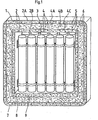
- Figure 1 shows the thermal insulation 1, which is limited by a double-walled housing 2. This has a cuboid cross section. T It has an interior 3, which in the embodiment shown here example serves to accommodate memory cells.
- the outer and inner housing walls 2A and 2B are made of steel or stainless steel.
- the two housing walls 2A and 2B are arranged parallel to one another at a predeterminable distance.
- the distance between the inner and outer housing walls 2A and 2B depends on the desired width of the space 6 to be formed, which is arranged between these walls and is guided all around.
- the outer metallic housing wall 2A is gas-tight, the same applies to the inner housing wall 2B.
- the room has a residual gas pressure of less than 0.1 mbar.
- the insulating material 4 is filled into it.
- the insulating material 4 consists of three layers 4A, 4B and 4C.
- the layers are arranged so that they run perpendicular to the end of the temperature gradient. All three layers 4A, 4B and 4C essentially consist of glass fibers.
- the layers are arranged one behind the other and directly adjoin one another.
- the outermost layer 4A additionally bears on the inner surface of the outer housing wall 2A, while the innermost layer 4C adjoins the outer surfaces of the inner housing wall 2B.
- the three layers 4A and 4B and 4C have different thicknesses.
- the outermost layer 4A is ten millimeters thick.
- the layer 4B adjoining it has a thickness of 15 mm, while the layer 4C lying on the inside is only 5 mm thick.
- Glass fibers 7, 8 and 9 are made from different glass materials. Glass fibers made of alkali lead silicate glass are preferably used for the production of layer 4A.
- Layer 4B is made of glass fibers, for the manufacture of which soft borosilicate glass is preferably used.
- the glass fibers 9, which are contained in the layer 4C, are made of a hard borosilicate glass.
- one of the layers or, if it makes sense, all three layers 4A, 4B and 4C can be doped with a highly disperse powder 5. It is also possible to use different powders for the doping. According to the invention, however, the powders should only have a particle size of 0.3 to 0.5 ⁇ m.
- Silicas are preferably suitable for the additional doping of the layers with one or more of the abovementioned powders.
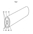
- FIG. 2 shows a further embodiment of the thermal insulation 1. This is arranged around a pipe system 20, within which hot flowing gases are transported. On the other hand, frozen media, such as liquid gases, can also be transported within the pipe system 20.
- the pipe system 20 is formed by two pipes 21 and 22 which have different diameters.
- the tube 21 provided with the smaller diameter is arranged concentrically within the tube 22. This creates a uniform space between the two tubes 21 and 22, which serves as space 6, which can be evacuated, and for receiving the insulating material 4. serves.
- the room 6 is sealed gas-tight by metallic washers (not shown here).
- the insulating material 4 is also formed here by three layers 4A, 4B and 4C, which are formed in the same way as the layers shown in FIG. 1.
- the three layers are arranged perpendicular to the temperature gradient. They have the same dimensions as the layers shown in FIG. 1. Additional doping of the layers with highly disperse powders is also possible and useful here.
- the invention is not only limited to the exemplary embodiments shown in FIGS. 1 and 2, but rather encompasses all thermal insulations which, as insulating material, have a plurality of layers which are made from different glass fibers and which have the property that their modulus of elasticity even at very high levels high temperatures do not fall below a specified minimum value.
Landscapes
- Engineering & Computer Science (AREA)
- Chemical & Material Sciences (AREA)
- Chemical Kinetics & Catalysis (AREA)
- Electrochemistry (AREA)
- General Chemical & Material Sciences (AREA)
- General Engineering & Computer Science (AREA)
- Manufacturing & Machinery (AREA)
- Mechanical Engineering (AREA)
- Thermal Insulation (AREA)
- Secondary Cells (AREA)
- Packages (AREA)
Abstract
Description
- Die Erfindung bezieht sich auf eine thermische Isolierung gemäß dem Oberbegriff des Patentanspruches 1.
- Solche thermischen Isolierungen kommen unter anderem in der Energietechnik zur Anwendung, insbesondere bei Einrichtungen, bei denen Wärmeverluste vermieden werden sollen. Thermische Isolierungen werden beispielsweise bei Hochtemperaturspeicherbatterien auf der Basis von Alkalimetall und Chalkogen verwendet. Die Speicherzellen, die zu einer Batterie zusammengeschaltet sind, werden zusätzlich von einer thermischen Isolierung umgeben, um die erforderliche Arbeitstemperatur der Speicherzellen, welche bei etwa 400 Grad Celsius liegt, aufrecht erhalten zu können, und die Abkühlung der Speicherzellen vor allem in den Betriebspausen der Hochtemperaturspeicherbatterie zu verhindern, damit auch nach den Pausen eine Temperatur von 350 bis 400 Grad Celsius in den Speicherzellen herrscht, was eine notwendige Voraussetzung für die optimale Funktionsweise der Speicherzellen ist.
- In der Patentanmeldung P 32 35 708.7 ist bereits eine thermische Isolierung beschrieben, die durch ein doppelwandiges Gehäuse begrenzt ist. Zwischen den beiden Gehäusewandungen ist ein evakuierter Raum vorgesehen, in den ein den Wärmefluß zwischen den Gehäusewandungen hemmende senkrecht zum Temperaturgradienden angeordnete Isoliermasse eingefüllt ist. Bei der hier beschriebenen Anordnung besteht das Isoliermaterial aus Fasern, vorzugsweise aus Glasfasern. Der Wärmetransport in einer solchen thermischen Isolierung, deren Isoliermaterial aus Fasern besteht setzt sich bei hinreichend niedrigem Restgasdruck innerhalb des evakuierten Raums aus einem Festkörperleitungs- und einem Strahlungsanteil zusammen. Den die Festkörperleitung bestimmenden Wärmewiderstand bilden die Kontaktflächen der senkrecht zum Temperaturgradienden ausgerichteten Glasfasern. Wird das Isoliermaterial hohen Temperaturen ausgesetzt, d.h. es herrscht im Inneren der thermischen Isolierung eine Temperatur von mehr als 350 Grad Celsius, so kann anhand von Messungen festgestellt werden, daß bei einer zusätzlichen Druckbelastung des Isoliermaterials die Festkörperleitfähigkeit mit steigender Temperatur zunimmt. Dies ist insbesondere bei einem Isoliermaterial festzustellen, das aus Glasfasern gefertigt ist, die aus einem Borsilikatglas hergestellt sind. Diese Erhöhung der Festkörperleitfähigkeit ist auf eine Vergrößerung der Faserkontaktflächen zurückzuführen, da der Elastizitätsmodul von Fasern aus handelsüblichen Gläsern expo--nentiell mit steigender Temperatur abfällt.
- Durch die Verwendung von Fasern, die aus Quarzglas oder aus Keramik hergestellt sind, kann dieser Nachteil vermieden werden, jedoch sind thermische Isolierungen, deren Isoliermaterial aus diesen Werkstoffen gefertigt ist, sehr teuer.
- Der Erfindung liegt deshalb die Aufgabe zugrunde eine thermische Isolierung mit einem Isoliermaterial aus Glasfasern so zu verbessern, daß auch bei Temperaturen zwischen 400 und 600 Grad im Inneren der thermischen Isolierung die Wärmeisolationseigenschaft des Isoliermaterials ebenso gut ist wie bei wesentlich niedrigeren Temperaturen.
- Diese Aufgabe wird erfindungsgemäß durch die kennzeichnenden Merkmale des Patentanspruches 1 gelöst.
- Erfindungsgemäß wird das in den evakuierten Raum der thermischen Isolierung eingefüllte Isoliermaterial nicht über die gesamte Dicke aus dem gleichen Werkstoff gefertigt. Vielmehr besteht das Isoliermaterial aus Glasfasern, die aus wenigstens zwei unterschiedlichen Glaswerkstoffen gefertigt sind. Erfindungsgemäß werden innerhalb des evakuierten Raumes drei Schichten aus Glasfasern so hintereinander angeordnet, daß sie senkrecht zum Temperaturgradienden angeordnet sind. Die Dicke der Schichten ist unterschiedlich groß gewählt, insbesondere wird sie durch den Temperaturabfall innerhalb des Isoliermaterials bestimmt. Erfindungsgemäß sind innerhalb des evakuierten Raums drei Schichten vorgesehen, die direkt aneinander liegen und wovon die äußerste Schicht an die Innenfläche der äußeren Gehäusewandung und die innerste Schicht an die Innenfläche der inneren Gehäusewandung angrenzt. Die äußere Schicht ist erfindungsgemäß 10 mm dick und aus Glasfasern gefertigt, die aus einem Alkali-Bleisilikatglas hergestellt sind. Die zwischen der inneren und äußeren Schicht liegende zweite Schicht ist 15 mm dick und aus Glasfasern gefertigt, welche aus einem Weich-Borsilikatglas hergestellt sind. Die dem Innenraum der Isolierung am nächsten liegende Schicht ist erfindungsgemäß 5 mm dick und aus Glasfasern gefertigt, die aus einem Hart-Borsilikatglas gefertigt sind. Das verwendete Isoliermaterial, insbesondere die Glasfasern weisen die Eigenschaft auf, daß ihr Elastizitätsmodul auch bei hohen Temperaturen, insbesondere bei Temperaturen von mehr als 400 Grad Celsius einen vorgegebenen Wert nicht unterschreitet. Vorzugsweise weisen Glasfasern aus Alkali-Bleisilikatglas bei einer Temperatur von 400 Grad Celsius einen Elastizitätsmodul von z.B. 4500 kg/mm2 auf. Der Elastizitätsmodul von Glasfasern aus Weichborsilikatglas unterschreitet einen Wert von z.B. 5500 kg/mm2 bei einer Temperatur von 400 Grad Celsius ebenfalls nicht. Das gleiche gilt für Glasfasern aus Hartborsilikatglas, die bei einer solchen Temperatur noch einen Elastizitätsmodul von z.B. 7500 kg/mm2 aufweisen.
- Erfindungsgemäß werden die Faserschichten zusätzlich mit einem oder meheren hochdispersen Pulvern dotiert. Die verwendeten Pulver sollten eine Teilchengröße aufweisen, die f 0,3 bis 0,5 µm beträgt.
- Die Erfindung wird nachfolgend anhand von Zeichnungen näher erläutert.
- Es zeigen:
- Figur 1: Eine thermische Isolierung im Vertikalschnitt,
- Figur 2: eine Rohrleitung mit der thermischen Isolierung.
- Figur 1 zeigt die thermische Isolierung 1, die von einem doppelwandigen Gehäuse 2 begrenzt ist. Dieses weist einen quaderförmigen Querschnitt auf.TEs besitzt einen Innenraum 3, der bei dem hier dargestellten Ausführungsbeispiel zur Aufnahme von Speicherzellen dient. Die äußere und innere Gehäusewandung 2A und 2B sind aus Stahl oder Edelstahl gefertigt. Die beiden Gehäusewandungen 2A und 2B sind in einem vorgebbaren Abstand parallel zueinander angeordnet. Der Abstand zwischen der inneren und äußeren Gehäusewandung 2A und 2B richtet sich nach der gewünschten Breite des zu bildenden Raumes 6, der zwischen diesen Wandungen angeordnet und rundum geführt ist. Die äußere metallische Gehäusewandung 2A ist gasdicht ausgebildet, das gleiche gilt für die innere Gehäusewandung 2B. Durch diese Maßnahmen wird erreicht, daß der Raum 6 gasdicht ausgebildet werden kann. Insbesondere besteht die Möglichkeit, diesen Raum 6 dauerhaft zu evakuieren. Bei dem hier gezeigten Ausführungsbeispiel weist der Raum einen Restgasdruck von weniger als 0,1 mbar auf. Vor dem gasdichten Verschließen und Evakuieren des Raumes 6 wird in diesen das Isoliermaterial 4 eingefüllt. Bei dem hier dargestellten Ausführungsbeispiel besteht das Isoliermaterial 4 aus drei Schichten 4A, 4B und 4C. Die Schichten sind so angeordnet, daß sie senkrecht zum Temperaturgradienden verlaufen. Alle drei Schichten 4A, 4B und 4C bestehen im wesentlichen aus Glasfasern. Die Schichten sind hintereinander angeordnet und grenzen direkt aneinander an. Die äußerste Schicht 4A liegt zusätzlich an der Innenfläche der äußeren Gehäusewandung 2A an, während die innerste Schicht 4C an dieAußenflächen der inneren Gehäusewandung 2B angrenzt. Die drei Schichten 4A und 4B und 4C sind unterschiedlich dick ausgebildet. Erfindungsgemäß ist die äußerste Schicht 4A zehn Millimeter dick. Die an sie anschließende Schicht 4B weist eine Dicke von 15 mm auf, während die ganz innen liegende Schicht 4C nur 5 mm dick ausgebildet ist. Die für die Herstellung der Schichten 4A, 4B und 4C verwendeten
- Glasfasern 7,8 und 9 sind aus unterschiedlichen Glaswerkstoffen hergestellt. Für die Fertigung der Schicht 4A werden vorzugsweise Glasfasern aus Alkali-Bleisilikatglas verwendet. Die Schicht 4B wird aus Glasfasern hergestellt, für deren Fertigung vorzugsweise Weich-Borsilikatglas benutzt wird. Die Glasfasern 9, die in der Schicht 4C enthalten sind, sind aus einem Hart-Borsilikatglas hergestellt. Zusätzlich kann eine der Schichten bzw. falls es sinnvoll ist, können alle drei Schichten 4A, 4B und 4C mit einem hochdispersen Pulver 5 dotiert werden. Es besteht die Möglichkeit für die Dotierung auch unterschiedliche Pulver zu verwenden. Erfindungsgemäß sollten die Pulver jedoch nur eine Teilchengröße von 0,3 bis 0,5 um aufweisen.
- Für die zusätzliche Dotierung der Schichten mit einem oder mehreren der oben genannten Pulver eignen sich vorzugsweise Kieselsäuren.
- Figur 2 zeigt eine weitere Ausführungsform der thermischen Isolierung 1. Diese ist hierbei um ein Rchrleitungssystem 20 angeordnet, innerhalb dessen heiße strömende Gase transportiert werden. Innerhalb des Rohrsystems 20 können andererseits auch tiefgekühlte Medien wie beispielsweise Flüssiggase transportiert werden. Das Rohrleitungssystem 20 wird durch zwei Rohre 21 und 22 gebildet, die unterschiedliche Durchmesser aufweisen. Insbesondere ist das mit dem kleineren Durchmesser versehene Rohr 21 kozentrisch innerhalb des Rohres 22 angeordnet. Dadurch wird ein gleichmäßiger Zwischenraum zwischen den beiden Rohren 21 und 22 geschaffen, der als Raum 6 dient, welcher evakuiert werden kann, und zur Aufnahme des Isoliermaterials 4 . dient. An den Enden dieser beiden Rohre 21 und 22 ist der Raum 6 durch metallische Ringscheiben (hier nicht dargestellt) gasdicht verschlossen. Das Isoliermaterial 4 wird auch hierbei durch drei Schichten 4A, 4B und 4C gebildet, die in gleicher Weise wie die in Figur 1 dargestellten Schichten ausgebildet sind. Die drei Schichten sind senkrecht zum Temperaturgradienten angeordnet. Sie weisen die gleichen Abmessungen auf, wie die in Figur 1 gezeigten Schichten. Eine zusätzliche Dotierung der Schichten mit hochdispersen Pulvern ist auch hierbei möglich und sinnvoll.
- Die Erfindung beschränkt sich nicht nur auf die in den Figuren 1 und 2 dargestellten Ausführungsbeispiele, vielmehr umfaßt sie alle thermischen Isolierungen, die als Isoliermaterial mehrere Schichten aufweisen, die aus unterschiedlichen Glasfasern gefertigt sind, und die die Eigenschaft aufweisen, daß ihre Elastizitätsmodule auch bei sehr hohen Temperaturen einen festgelegten Mindestwert nicht unterschreiten.
Claims (8)
Applications Claiming Priority (2)
| Application Number | Priority Date | Filing Date | Title |
|---|---|---|---|
| DE3345141 | 1983-12-14 | ||
| DE19833345141 DE3345141A1 (de) | 1983-12-14 | 1983-12-14 | Thermische isolierung |
Publications (2)
| Publication Number | Publication Date |
|---|---|
| EP0149090A1 true EP0149090A1 (de) | 1985-07-24 |
| EP0149090B1 EP0149090B1 (de) | 1988-06-08 |
Family
ID=6216866
Family Applications (1)
| Application Number | Title | Priority Date | Filing Date |
|---|---|---|---|
| EP84114638A Expired EP0149090B1 (de) | 1983-12-14 | 1984-12-01 | Thermische Isolierung |
Country Status (4)
| Country | Link |
|---|---|
| US (1) | US4598005A (de) |
| EP (1) | EP0149090B1 (de) |
| JP (1) | JPS60168988A (de) |
| DE (1) | DE3345141A1 (de) |
Cited By (4)
| Publication number | Priority date | Publication date | Assignee | Title |
|---|---|---|---|---|
| DE10125964A1 (de) * | 2001-05-29 | 2002-12-12 | Oesterr Heraklith Gmbh | Formkörper |
| DE102007049327A1 (de) * | 2007-10-12 | 2009-04-23 | Springfix-Befestigungstechnik Gmbh | Thermisch isolierender Behälter sowie ein Verfahren zur Herstellung eines thermisch isolierenden Behälters |
| WO2012100899A1 (de) * | 2011-01-28 | 2012-08-02 | Li-Tec Battery Gmbh | Transportvorrichtung für elektrochemische energiespeichervorrichtungen |
| WO2015110613A1 (en) * | 2014-01-23 | 2015-07-30 | Spark Racing Technology Sas | Protective battery casing |
Families Citing this family (9)
| Publication number | Priority date | Publication date | Assignee | Title |
|---|---|---|---|---|
| AT388428B (de) * | 1987-08-21 | 1989-06-26 | Scholz Zbynek | Waermeisolierungsvorrichtung |
| DE4334282A1 (de) * | 1993-10-08 | 1995-04-13 | Aeg Anglo Batteries Germany Gm | Doppelwandiges Gehäuse |
| US7344046B1 (en) * | 2003-11-19 | 2008-03-18 | Matrix Service, Inc. | Spacerless or geocomposite double bottom for storage tank |
| GB2448292A (en) * | 2007-04-14 | 2008-10-15 | Royston William Clarke | Thermal insulation of batteries |
| US9005748B1 (en) | 2011-03-04 | 2015-04-14 | Insulating Coatings Of America, Inc. | Coating containing borosilicate flake glass |
| WO2013184581A1 (en) * | 2012-06-03 | 2013-12-12 | Insulating Coatings Of America, Inc. | Flaked borosilicate glass coatings |
| JP6433052B2 (ja) * | 2014-09-09 | 2018-12-05 | 理研計器株式会社 | ガス測定装置用素子 |
| GB2545214A (en) * | 2015-12-09 | 2017-06-14 | Jaguar Land Rover Ltd | Apparatus for providing a barrier between battery modules |
| DE102019210367A1 (de) * | 2019-02-04 | 2020-08-06 | Volkswagen Aktiengesellschaft | Sicherheitsbehälter für galvanische Zellen |
Citations (4)
| Publication number | Priority date | Publication date | Assignee | Title |
|---|---|---|---|---|
| DE3038142A1 (de) * | 1980-10-09 | 1982-04-29 | Brown, Boveri & Cie Ag, 6800 Mannheim | Thermische isolierung |
| DE3046032A1 (de) * | 1980-12-06 | 1982-07-15 | Brown, Boveri & Cie Ag, 6800 Mannheim | "thermische isolierung" |
| DE3304738A1 (de) * | 1982-02-12 | 1983-08-25 | Kennecott Corp., 06904 Stamford, Conn. | Nahtlose verbunderzeugnisse aus keramikfasern sowie verfahren und vorrichtung zu ihrer herstellung |
| DE3235708A1 (de) * | 1982-09-27 | 1984-03-29 | Brown, Boveri & Cie Ag, 6800 Mannheim | Thermische isolierung |
Family Cites Families (5)
| Publication number | Priority date | Publication date | Assignee | Title |
|---|---|---|---|---|
| US3053715A (en) * | 1958-03-17 | 1962-09-11 | Johns Manville Fiber Glass Inc | High temperature pipe insulation and method of making same |
| US3698588A (en) * | 1970-10-21 | 1972-10-17 | Louis A Pogorski | Thermally insulated device |
| US3695483A (en) * | 1970-11-27 | 1972-10-03 | Louis A Pogorski | Thermal insulation and thermally insulated device |
| US4201247A (en) * | 1977-06-29 | 1980-05-06 | Owens-Corning Fiberglas Corporation | Fibrous product and method and apparatus for producing same |
| JPS557428A (en) * | 1978-06-30 | 1980-01-19 | Yuasa Battery Co Ltd | Multilayer heat insulator |
-
1983
- 1983-12-14 DE DE19833345141 patent/DE3345141A1/de not_active Withdrawn
-
1984
- 1984-12-01 EP EP84114638A patent/EP0149090B1/de not_active Expired
- 1984-12-12 US US06/681,114 patent/US4598005A/en not_active Expired - Fee Related
- 1984-12-13 JP JP59261931A patent/JPS60168988A/ja active Pending
Patent Citations (4)
| Publication number | Priority date | Publication date | Assignee | Title |
|---|---|---|---|---|
| DE3038142A1 (de) * | 1980-10-09 | 1982-04-29 | Brown, Boveri & Cie Ag, 6800 Mannheim | Thermische isolierung |
| DE3046032A1 (de) * | 1980-12-06 | 1982-07-15 | Brown, Boveri & Cie Ag, 6800 Mannheim | "thermische isolierung" |
| DE3304738A1 (de) * | 1982-02-12 | 1983-08-25 | Kennecott Corp., 06904 Stamford, Conn. | Nahtlose verbunderzeugnisse aus keramikfasern sowie verfahren und vorrichtung zu ihrer herstellung |
| DE3235708A1 (de) * | 1982-09-27 | 1984-03-29 | Brown, Boveri & Cie Ag, 6800 Mannheim | Thermische isolierung |
Cited By (5)
| Publication number | Priority date | Publication date | Assignee | Title |
|---|---|---|---|---|
| DE10125964A1 (de) * | 2001-05-29 | 2002-12-12 | Oesterr Heraklith Gmbh | Formkörper |
| DE102007049327A1 (de) * | 2007-10-12 | 2009-04-23 | Springfix-Befestigungstechnik Gmbh | Thermisch isolierender Behälter sowie ein Verfahren zur Herstellung eines thermisch isolierenden Behälters |
| WO2012100899A1 (de) * | 2011-01-28 | 2012-08-02 | Li-Tec Battery Gmbh | Transportvorrichtung für elektrochemische energiespeichervorrichtungen |
| WO2015110613A1 (en) * | 2014-01-23 | 2015-07-30 | Spark Racing Technology Sas | Protective battery casing |
| US10270081B2 (en) | 2014-01-23 | 2019-04-23 | Spark Racing Technology Sas | Protective battery casing |
Also Published As
| Publication number | Publication date |
|---|---|
| DE3345141A1 (de) | 1985-06-27 |
| EP0149090B1 (de) | 1988-06-08 |
| US4598005A (en) | 1986-07-01 |
| JPS60168988A (ja) | 1985-09-02 |
Similar Documents
| Publication | Publication Date | Title |
|---|---|---|
| EP0090191B1 (de) | Thermische Isolierung | |
| EP0104511B1 (de) | Thermische Isolierung | |
| EP0149090B1 (de) | Thermische Isolierung | |
| DE2730399A1 (de) | Verfahren und vorrichtung zur waermeuebertragung | |
| DE3038142C2 (de) | Thermische Isolierung | |
| DE1936641A1 (de) | Rohranordnung und Abstandsband hierfuer | |
| DE1464123A1 (de) | Kernreaktor | |
| EP0209683B1 (de) | Thermische Isolierung | |
| EP0289456A1 (de) | Siegelbacke für Verpackungsmaschinen | |
| DE69011775T2 (de) | Verbesserte Metall-Keramik-Schmelzverbindung. | |
| DE3219506A1 (de) | Thermische isolierung | |
| DE2148963A1 (de) | Behaelter fuer Kaeltemittel | |
| DE1614932B2 (de) | Brennelement fuer schnelle kernreaktoren | |
| DE3046032A1 (de) | "thermische isolierung" | |
| CH664205A5 (de) | Waermeisoliertes leitungsrohr. | |
| DE3242900C2 (de) | ||
| DE2252069A1 (de) | Verfahren zum verbinden zweier metallflaechen und dadurch erhaltene bauteile | |
| DE2156171C2 (de) | Nukleares Brennelement mit mehreren Brennstoffröhren | |
| DE1218072B (de) | Sekundaerelektronenvervielfacher und Verfahren zur Herstellung des Vervielfachers | |
| DE3131864C1 (de) | Rohrverteiler fuer Fernheizungen | |
| DE1439843C3 (de) | Atomkernreaktor | |
| DE3146017A1 (de) | "thermische isolierung" | |
| DE2111080C3 (de) | Abstandshalter für koaxiale Rohrsysteme | |
| DE2825937A1 (de) | Abstandswendel fuer koaxiale rohrsysteme | |
| DE3843907A1 (de) | Thermische isolierung |
Legal Events
| Date | Code | Title | Description |
|---|---|---|---|
| PUAI | Public reference made under article 153(3) epc to a published international application that has entered the european phase |
Free format text: ORIGINAL CODE: 0009012 |
|
| AK | Designated contracting states |
Designated state(s): BE FR GB IT NL |
|
| 17P | Request for examination filed |
Effective date: 19860109 |
|
| 17Q | First examination report despatched |
Effective date: 19870226 |
|
| GRAA | (expected) grant |
Free format text: ORIGINAL CODE: 0009210 |
|
| AK | Designated contracting states |
Kind code of ref document: B1 Designated state(s): BE FR GB IT NL |
|
| ITF | It: translation for a ep patent filed | ||
| GBT | Gb: translation of ep patent filed (gb section 77(6)(a)/1977) | ||
| ET | Fr: translation filed | ||
| RAP2 | Party data changed (patent owner data changed or rights of a patent transferred) |
Owner name: ASEA BROWN BOVERI AKTIENGESELLSCHAFT |
|
| BECN | Be: change of holder's name |
Effective date: 19880608 |
|
| ITTA | It: last paid annual fee | ||
| NLT2 | Nl: modifications (of names), taken from the european patent patent bulletin |
Owner name: ASEA BROWN BOVERI AKTIENGESELLSCHAFT TE MANNHEIM-K |
|
| PLBE | No opposition filed within time limit |
Free format text: ORIGINAL CODE: 0009261 |
|
| STAA | Information on the status of an ep patent application or granted ep patent |
Free format text: STATUS: NO OPPOSITION FILED WITHIN TIME LIMIT |
|
| 26N | No opposition filed | ||
| PGFP | Annual fee paid to national office [announced via postgrant information from national office to epo] |
Ref country code: GB Payment date: 19891031 Year of fee payment: 6 |
|
| PGFP | Annual fee paid to national office [announced via postgrant information from national office to epo] |
Ref country code: FR Payment date: 19891124 Year of fee payment: 6 |
|
| PGFP | Annual fee paid to national office [announced via postgrant information from national office to epo] |
Ref country code: BE Payment date: 19891130 Year of fee payment: 6 |
|
| PGFP | Annual fee paid to national office [announced via postgrant information from national office to epo] |
Ref country code: NL Payment date: 19891231 Year of fee payment: 6 |
|
| PG25 | Lapsed in a contracting state [announced via postgrant information from national office to epo] |
Ref country code: GB Effective date: 19901201 |
|
| PG25 | Lapsed in a contracting state [announced via postgrant information from national office to epo] |
Ref country code: BE Effective date: 19901231 |
|
| BERE | Be: lapsed |
Owner name: ASEA BROWN BOVERI A.G. Effective date: 19901231 |
|
| PG25 | Lapsed in a contracting state [announced via postgrant information from national office to epo] |
Ref country code: NL Effective date: 19910701 |
|
| GBPC | Gb: european patent ceased through non-payment of renewal fee | ||
| NLV4 | Nl: lapsed or anulled due to non-payment of the annual fee | ||
| PG25 | Lapsed in a contracting state [announced via postgrant information from national office to epo] |
Ref country code: FR Effective date: 19910830 |
|
| REG | Reference to a national code |
Ref country code: FR Ref legal event code: ST |