EP0148997A1 - Heat exchanger with a multitude of soot blowers - Google Patents
Heat exchanger with a multitude of soot blowers Download PDFInfo
- Publication number
- EP0148997A1 EP0148997A1 EP84110433A EP84110433A EP0148997A1 EP 0148997 A1 EP0148997 A1 EP 0148997A1 EP 84110433 A EP84110433 A EP 84110433A EP 84110433 A EP84110433 A EP 84110433A EP 0148997 A1 EP0148997 A1 EP 0148997A1
- Authority
- EP
- European Patent Office
- Prior art keywords
- soot blower
- compressor
- sootblower
- medium
- air
- Prior art date
- Legal status (The legal status is an assumption and is not a legal conclusion. Google has not performed a legal analysis and makes no representation as to the accuracy of the status listed.)
- Granted
Links
- 239000004071 soot Substances 0.000 title claims abstract description 46
- 238000011010 flushing procedure Methods 0.000 claims description 11
- 230000004888 barrier function Effects 0.000 claims description 6
- 238000007664 blowing Methods 0.000 claims description 6
- 230000000903 blocking effect Effects 0.000 claims description 2
- 238000004140 cleaning Methods 0.000 claims description 2
- 238000010438 heat treatment Methods 0.000 claims description 2
- 238000010408 sweeping Methods 0.000 abstract 1
- 238000010926 purge Methods 0.000 description 18
- 238000007789 sealing Methods 0.000 description 17
- 239000007789 gas Substances 0.000 description 7
- 239000003546 flue gas Substances 0.000 description 5
- UGFAIRIUMAVXCW-UHFFFAOYSA-N Carbon monoxide Chemical compound [O+]#[C-] UGFAIRIUMAVXCW-UHFFFAOYSA-N 0.000 description 4
- 239000000779 smoke Substances 0.000 description 4
- 230000007797 corrosion Effects 0.000 description 1
- 238000005260 corrosion Methods 0.000 description 1
- 230000001419 dependent effect Effects 0.000 description 1
- 238000006073 displacement reaction Methods 0.000 description 1
- 230000000694 effects Effects 0.000 description 1
- 239000000446 fuel Substances 0.000 description 1
- 210000003127 knee Anatomy 0.000 description 1
- 239000007788 liquid Substances 0.000 description 1
- 230000035515 penetration Effects 0.000 description 1
- 230000001105 regulatory effect Effects 0.000 description 1
- 230000002000 scavenging effect Effects 0.000 description 1
- 239000007787 solid Substances 0.000 description 1
Images

Classifications
-
- F—MECHANICAL ENGINEERING; LIGHTING; HEATING; WEAPONS; BLASTING
- F28—HEAT EXCHANGE IN GENERAL
- F28G—CLEANING OF INTERNAL OR EXTERNAL SURFACES OF HEAT-EXCHANGE OR HEAT-TRANSFER CONDUITS, e.g. WATER TUBES OR BOILERS
- F28G3/00—Rotary appliances
- F28G3/16—Rotary appliances using jets of fluid for removing debris
Definitions
- the invention relates to a soot blower for cleaning heating surfaces in a heat exchanger with the features of the preamble of claim 1.
- the smoke gases in the heat exchanger which are produced when solid, liquid or gaseous fuels are burned, are connected to the lance tube of the sootblower via the nozzles and can penetrate into it.
- the mostly aggressive and hot gases cause damage due to corrosion or pollution.
- a harmless, gaseous flushing medium for example air
- a barrier medium for example air
- the purge air and the sealing air are taken from a central blower in heat exchangers, especially in power plant boilers that are equipped with a large number of soot blowers, and distributed to the individual soot blowers.
- This requires a complex piping system. Because of the mostly low pressure level of the central blowers used, relatively large line cross sections are often required in order to keep the friction losses low.
- a separate control device is required in front of each soot blower in order to ensure that the required air volumes are distributed as evenly as possible to ensure the different friction losses due to the different pipe lengths to the individual soot blowers.
- the connections on the sootblower valve and / or on the wall box must be made flexible because of the thermal expansion of the heat exchanger and the movement of the sootblower caused thereby.
- a procedural requirement of many manufacturers and operators of heat exchangers is, moreover, that the amount of air introduced per soot blower should remain as small as possible and should not exceed a maximum value even in the event of frequent fluctuations in the flue gas side.
- the invention has for its object to simplify the known system for supplying the soot blower with flushing and blocking medium.
- the central blower and the complex air distribution system can be dispensed with, since the flushing and sealing air can be generated on each soot blower by its own compressor.
- This compressor and the distribution pipes on the soot blower are designed so that each soot blower always receives the required amount of purge air and sealing air. The necessary rough adjustment can be made at the manufacturer.
- the soot blower shown has a lance tube 1 which is provided with nozzles 2 at its front end.
- the lance tube 1 is connected to a gear carriage 4 driven by a motor 3, which can be moved together with the lance tube 1 on a stationary mounting rail 5.
- the motor 3 also sets the lance tube 1 in a rotational movement, so that the nozzles 2 perform a helical movement overall.
- the end points of the travel path of the lance tube 1 are each determined by a fixed limit switch.
- the lance tube 1 can be moved through an inlet opening into a heat exchanger, the wall of which is indicated by a wall tube 6.
- the inlet opening is surrounded by a wall box 7 for sealing against the outside atmosphere.
- the lance tube 1 with the nozzles 2 is located inside the wall box 7.
- the displaceable lance tube 1 surrounds a stationary inner tube 8, the rear end of which has a connection for a blowing medium, for example steam.
- the amount of the blowing medium is regulated via a sootblower valve 9 arranged on the sootblower.
- the inner tube 8 is provided with a connection 10 for a flushing medium, for example air.
- the purge air connection 10 is above the valve seat of the soot blower valve 9, d. H. arranged in the flow direction of the blowing medium behind the soot blower valve 9.
- the lance tube 1 is supplied with purge air which emerges from the nozzles 2.
- a non-return valve 12 is arranged in a purging air line 11 leading to the purging air connection 10 and is set such that the blowing medium cannot penetrate the purging air line 11 after the soot blower valve 9 has been opened.
- the wall box 7 is provided with a connection 13 for a barrier medium, for example air.
- the sealing air connection 13 is connected via a flexible line 14 to a sealing air line 15 laid on the soot blower.
- the pressure of the purge air and the sealing air is above the gas pressure prevailing in the heat exchanger.
- the purge air and the sealing air are generated by a device specific to each soot blower, which is formed by a compressor 16 which is attached to the soot blower.
- the compressor 16 is connected to the soot blower in the workshop to form a unit. In doing so, too the electrical connection cables for driving the compressor 16 and for the motor 3 of the soot blower drive to a central terminal box and electrically secured there.
- the compressor 16 is arranged in the vicinity of the soot blower valve 9;
- An air line 17 is connected to the outlet of the compressor 16 and leads to a knee piece 18.
- the sealing air pipe 15 branches to the barrier air connection 13 on the W andkasten 7 and the purge air 11 to the purging air connection 10 from.
- a safety valve 19 is provided in the air line 17, the response pressure of which corresponds to the design pressure of the compressor 16.
- the V-tight ER- 16 it is preferably an embodiment which has a largely independent of the height of the flue gas side backpressure delivery. Compressors operating according to the displacement principle, such as piston and rotary piston compressors, can be used.
- a side channel compressor which can work largely independently of the back pressure in the pressure range of 0.99 to 1.02 bar, which is of interest to the sootblower, but is considerably lower in cost than the previously mentioned types of compressors.
- these compressor designs it can be ensured that the delivery volume does not increase, or increases only insignificantly, even when the counterpressure on the flue gas side is lower than the design point of the compressor 16 is essentially dependent on the prevailing back pressure.
- the sealing air connection 13 on the wall box 7 can be omitted.
- This solution is so advantageous because the flexible lines 14 required due to the movement of the heat exchanger wall can be omitted.
- this version can only be selected if the flue gas-side overpressure is low, so that it can be accepted that no air is emitted during the blowing operation of the sootblower.
- the check valve 12 is in fact closed and the compressor 16 is switched off or blows off via the safety valve 19.
- separate purge air connections 10 and sealing air connections 13 must be provided, as shown.
- the compressor 16 is arranged directly on the wall box 7.
- the sealing air connection 13 is rigidly connected to the wall box 7.
- the air blown into the wall box 7 can simultaneously serve as sealing air and purge air and ensure that the flue gases cannot escape from the heat exchanger into the open or penetrate into the soot blower.
- M ust a separateforementioned'von sealing air and scavenging air to be provided, so in the air line 17 is, as shown in FIG. 3, the elbow 18 with a branch off un g g to provide the purge air 15 °.
- a separate purge air and seal air supply is also necessary at such Rußbläsertypen in which the nozzles 2 of the B Las tube even remain in the heat exchanger when the sootblower is not in operation, that the soot blower valve is closed.
- an object of the S can pül- air and the sealing air to each of the embodiments shown in FIGS. 2 and 3 are selected.
- the control of the compressor 16 can be operated in such a way that the compressor 16 runs continuously, that is to say also during the soot blower operation with the soot blower valve 9 open and the check valve 12 closed.
- the control is preferably carried out in such a way that the compressor 16 is turned off when the soot blower is in operation.
- the switch-on and switch-off pulses for the electrical drive of the compressor 16 are removed by the contactors of the sootblower control, which are controlled by the limit switches of the sootblower.
Landscapes
- Engineering & Computer Science (AREA)
- Chemical & Material Sciences (AREA)
- Combustion & Propulsion (AREA)
- Mechanical Engineering (AREA)
- General Engineering & Computer Science (AREA)
- Incineration Of Waste (AREA)
- Heat-Exchange Devices With Radiators And Conduit Assemblies (AREA)
Abstract
Description
Die Erfindung betrifft einen Rußbläser zum Reinigen von Heizflächen in einem Wärmetauscher mit den Merkmalen des Oberbegriffes des Anspruches 1.The invention relates to a soot blower for cleaning heating surfaces in a heat exchanger with the features of the preamble of
Bei diesen Rußbläsern stehen die im Wärmetauscher befindlichen, bei der Verbrennung fester, flüssiger oder gasförmiger Brennstoffe entstehenden Rauchgase über die Düsen mit dem Lanzenrohr des Rußbläsers in Verbindung und können in dieses eindringen. Die meist aggressiven und heißen Gase führen dort zu Schäden infolge von Korrosion oder Verschmutzung.In these sootblowers, the smoke gases in the heat exchanger, which are produced when solid, liquid or gaseous fuels are burned, are connected to the lance tube of the sootblower via the nozzles and can penetrate into it. The mostly aggressive and hot gases cause damage due to corrosion or pollution.
Um diese Nachteile auszuschließen, wird oberhalb des Rußbläserventils ein unschädliches, gasförmiges Spülmedium zum Beispiel Luft eingeleitet, deren Druck etwas höher als der rauchgasseitige Druck im Wärmetauscher ist. Hierdurch wird eine Strömung des unschädlichen Spülmediums durch das Lanzenrohr des Rußbläsers in Richtung des Wärmetauschers bewirkt, die das Eindringen der aggressiven Rauchgase an den Düsen vermeidet. Ebenfalls zum Zweck der Abdichtung wird an dem Eintritt des Lanzenrohres in den Wärmetauscher ein Sperrmedium, zum Beispiel Luft in den die Eintrittsstelle umgebenden Wandkasten eingeblasen.In order to rule out these disadvantages, a harmless, gaseous flushing medium, for example air, is introduced above the soot blower valve, the pressure of which is somewhat higher than the pressure in the heat exchanger on the flue gas side. This causes a flow of the harmless flushing medium through the lance tube of the soot blower in the direction of the heat exchanger, which avoids the penetration of the aggressive smoke gases at the nozzles. Also for the purpose of sealing, a barrier medium, for example air, is blown into the wall box surrounding the entry point at the entry of the lance tube into the heat exchanger.
Die Spülluft und die Sperrluft werden bei Wärmetauschern insbesondere bei Kraftwerkskesseln, die mit einer Vielzahl von Rußbläsern ausgestattet sind, einem zentralen Gebläse entnommen.und auf die einzelnen Rußbläser verteilt. Hierzu ist ein aufwendiges Rohrleitungssystem erforderlich. Wegen der meist nur geringen Druckhöhe der verwendeten zentralen Gebläse werden häufig relativ große Leitungsquerschnitte erforderlich, um die Reibungsverluste gering zu halten. Weiterhin ist vor jedem Rußbläser ein gesondertes Regelorgan erforderlich, um die möglichst gleichmäßige Verteilung der erforderlichen Luftmengen trotz der unterschiedlichen Reibungsverluste infolge der nicht gleichen Rohrleitungslängen zu den einzelnen Rußbläsern zu gewährleisten. Schließlich müssen die Anschlüsse am Rußbläserventil und/oder am Wandkasten wegen der Wärmedehnungen des Wärmetauschers und der dadurch verursachten Bewegung des Rußbläsers flexibel ausgeführt werden.The purge air and the sealing air are taken from a central blower in heat exchangers, especially in power plant boilers that are equipped with a large number of soot blowers, and distributed to the individual soot blowers. This requires a complex piping system. Because of the mostly low pressure level of the central blowers used, relatively large line cross sections are often required in order to keep the friction losses low. Furthermore, a separate control device is required in front of each soot blower in order to ensure that the required air volumes are distributed as evenly as possible to ensure the different friction losses due to the different pipe lengths to the individual soot blowers. Finally, the connections on the sootblower valve and / or on the wall box must be made flexible because of the thermal expansion of the heat exchanger and the movement of the sootblower caused thereby.
Ein weiterer Nachteil des zentralen Luftsystems besteht darin, daß häufig die Luft einem vorhandenen Gebläse entnommen wird, das bei Abstellen des Wärmetauschers normalerweise außer Betrieb genommen wird. Das hat zur Folge, daß die noch längere Zeit vorhandene Kaminwirkung innerhalb des noch heißen Wärmetauschers die unerwünschten Rauchgase in das Lanzenrohr der Rußbläser oder aus der Wandöffnung des Wärmetauschers nach außen treibt.Another disadvantage of the central air system is that the air is often extracted from an existing fan, which is normally taken out of operation when the heat exchanger is switched off. The result of this is that the chimney effect which is still present for a long time within the still hot heat exchanger drives the undesired smoke gases into the lance tube of the sootblower or out of the wall opening of the heat exchanger.
Eine verfahrenstechnisch bedingte Forderung vieler Hersteller und Betreiber von Wärmetauschern ist darüber hinaus, daß die pro Rußbläser eingeleitete Luftmenge möglichst gering bleiben soll und auch bei häufig vorkommenden rauchgasseitigen Druckschwankungen einen Maximalwert nicht übersteigen soll.A procedural requirement of many manufacturers and operators of heat exchangers is, moreover, that the amount of air introduced per soot blower should remain as small as possible and should not exceed a maximum value even in the event of frequent fluctuations in the flue gas side.
Der Erfindung liegt die Aufgabe zugrunde, das bekannte System zur Versorgung des Rußbläsers mit Spül- und Sperrmedium zu vereinfachen.The invention has for its object to simplify the known system for supplying the soot blower with flushing and blocking medium.
Diese Aufgabe wird erfindungsgemäß durch die Merkmale des Anspruches 1 gelöst. Vorteilhafte Ausgestaltungen der Erfindung sind in den Unteransprüchen gekennzeichnet.This object is achieved by the features of
Durch die Erfindung wird erreicht, daß auf das zentrale Gebläse und das aufwendige Luftverteilsystem verzichtet werden kann, da die Spül- und Sperrluft durch einen eigenen Verdichter an jedem Rußbläser selbst erzeugt werden kann.It is achieved by the invention that the central blower and the complex air distribution system can be dispensed with, since the flushing and sealing air can be generated on each soot blower by its own compressor.
Dieser Verdichter und die Verteilrohre am Rußbläser sind so ausgelegt, daß jeder Rußbläser stets die erforderliche Menge an Spülluft und Sperrluft erhält. Die notwendige Grobeinstellung kann beim Hersteller vorgenommen werden.This compressor and the distribution pipes on the soot blower are designed so that each soot blower always receives the required amount of purge air and sealing air. The necessary rough adjustment can be made at the manufacturer.
Mehrere Ausführungsbeispiele der Erfindung sind in der Zeichnung dargestellt und werden im folgenden näher erläutert.Several embodiments of the invention are shown in the drawing and are explained in more detail below.
Es zeigen: -
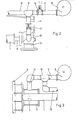
- Fig, 1 die Seitenansicht eines Rußbläsers gemäß der Erfindung,
- Fig. 2 die Einzelheit Y nach Fig. 1 und
- Fig. 3 die Einzelheit Z nach Fig. 1 für eine andere Ausführungsform der Erfindung.
-
Fi g, 1 is a side view of a sootblower according to the invention, - Fig. 2 shows the detail Y of FIG. 1 and
- Fig. 3 shows the detail Z of FIG. 1 for another embodiment of the invention.
In der Zeichnung ist ein Langrohr-Schraubrußbläser dargestellt. Bis auf die später noch erwähnten Einzelheiten ist die Erfindung in gleicher Weise auch auf andere Rußbläsertypen anzuwenden.In the drawing, a long tube soot blower is shown. Except for the details mentioned later, the invention is equally applicable to other types of sootblower.
Der dargestellte Rußbläser weist ein Lanzenrohr 1 auf, das an seinem vorderen Ende mit Düsen 2 versehen ist. Das Lanzenrohr 1 ist mit einem von einem Motor 3 angetriebenen Getriebewagen 4 verbunden, der zusammen mit dem Lanzenrohr 1 auf einer ortsfesten Tragschiene 5 verfahrbar ist. Der Motor 3 versetzt das Lanzenrohr 1 zusätzlich in eine Drehbewegung, so daß die Düsen 2 insgesamt eine schraubenlinienförmige Bewegung ausführen. Die Endpunkte des Fahrweges des Lanzenrohres 1 sind durch je einen ortsfesten Endschalter bestimmt.The soot blower shown has a
Das Lanzenrohr 1 ist durch eine Eintrittsöffnung in einen Wärmetauscher einfahrbar, dessen Wandung durch ein Wandrohr 6 angedeutet ist. Die Eintrittsöffnung ist von einem Wandkasten 7 zur Abdichtung gegenüber der Außenatmosphäre umgeben. Im zurückgezogenen Zustand befindet sich das Lanzenrohr 1 mit den Düsen 2 innerhalb des Wandkastens 7.The
Das verschiebbare Lanzenrohr 1 umgibt ein ortsfestes Innenrohr 8, dessen hinteres Ende einen Anschluß für ein Blasmedium, zum Beispiel Dampf aufweist. Die Menge des Blasmediums wird über ein auf dem Rußbläser angeordnetes Rußbläserventil 9 geregelt.The
Das Innenrohr 8 ist mit einem Anschluß 10 für ein Spülmedium, zum Beispiel Luft versehen. Der Spülluftanschluß 10 ist oberhalb des Ventilsitzes des Rußbläserventils 9, d. h. in Strömungsrichtung des Blasmediums hinter dem Rußbläserventil 9, angeordnet. über den Spülluftanschluß 10 und das Innenrohr 8 wird das Lanzenrohr 1 mit Spülluft versorgt, die aus den Düsen 2 austritt. In einer zu dem Spülluftanschluß 10 führenden Spülluftleitung 11 ist ein Rückschlagventil 12 angeordnet und derart eingestellt, daß das Blasmedium nach einem öffnen des Rußbläserventils 9 nicht durch die Spülluftleitung 11 dringen kann.The
Der Wandkasten 7 ist mit einem Anschluß 13 für ein Sperrmedium, zum Beispiel Luft versehen. Der Sperrluftanschluß 13 ist über eine flexible Leitung 14 mit einer auf dem Rußbläser verlegten Sperrluftleitung 15 verbunden. Der Druck der Spülluft und der Sperrluft liegt oberhalb des in dem Wärmetauscher herrschenden Gasdruckes.The
Die Spülluft und die Sperrluft werden von einer jedem Rußbläser eigenen Einrichtung erzeugt, die durch einen Verdichter 16 gebildet ist, der an dem Rußbläser angebaut ist. Der Verdichter 16 wird mit dem Rußbläser in der Werkstatt zu einer Einheit verbunden. Dabei werden auch die elektrischen Anschlußkabel für den Antrieb des Verdichters 16 sowie für den Motor 3 des Rußbläserantriebes zu einem zentralen Klemmkasten geführt und dort elektrisch abgesichert.The purge air and the sealing air are generated by a device specific to each soot blower, which is formed by a
Nach den Figuren 1 und 2 ist der Verdichter 16 in der Nähe des Rußbläserventils 9 angeordnet; An den Ausgang des Verdichters 16 ist eine Luftleitung 17 angeschlossen, die zu einem Kniestüökh18 führt. Von dem Kniestück 18 zweigt die Sperrluftleitung 15 zu dem Sperrluftanschluß 13 am Wandkasten 7 und die Spülluftleitung 11 zu dem Spülluftanschluß 10 ab. In der Luftleitung 17 ist ein Sicherheitsventil 19 vorgesehen, dessen Ansprechdruck dem Auslegungsdruck des Verdichters 16 entspricht. Bei dem Ver- dichter 16 handelt es sich vorzugsweise um eine Ausführung, die ein von der Höhe des rauchgasseitigen Gegendruckes weitgehend unabhängiges Fördervolumen hat. Eingesetzt werden können nach dem Verdrängerprinzip arbeitende Verdichter, wie etwa Kolben- und Drehkolbenverdichter. Als besonders vorteilhaft bietet sich die Verwendung eines Seitenkanalverdichters an, der in dem für die Rußbläser interessanten Druckbereich von 0,99 bis 1,02 bar weitgehend unabhängig vom Gegendruck arbeiten kann, jedoch hinsichtlich seiner Anschaffungskosten erheblich unter den vorher genannten Verdichtertypen liegt. Mit diesen Verdichterausführungen kann gewährleistet werden, daß das Fördervolumen auch bei niedrigeren Gegendrücken der Rauchgasseite als dem Auslegungspunkt des Verdichters 16 das Fördervolumen nicht oder nur unwesentlich steigt.Hierin ist ein deutlicher Vorteil gegenüber den für die bekannten zentralen Luftsysteme verwendeten Radialgebläse zu sehen, deren Betriebspunkt sehr wesentlich vom jeweils herrschenden Gegendruck abhängig ist.According to FIGS. 1 and 2, the
Ein weiterer Vorteil der genannten Verdichter gegenüber Radialgebläsen ist die Möglichkeit gegen relativ hohe Gegendrücke arbeiten zu können, so daß größere Reibungswiderstände innerhalb des Rußbläsers überwunden werden können. Hierdurch ergibt sich die Möglichkeit, die in den Rußbläsern eingeleitete Luft sowohl als Spülluft als auch als Sperrluft zu verwenden, wenn es sich um einen Rußbläsertyp wie den dargestellten Langrohr-Schraubenrußbläser handelt, bei dem die Düsen 2 am Ende des Lanzenrohres 1 im Ruhestand innerhalb des Wandkastens 7 stehen. Somit sorgt die aus den Düsen 2 ausströmende Luft einerseits dafür, daß keine Rauchgase in den Rußbläser eindringen und andererseits für die Abdichtung der Wärmetauscherwand. Dadurch kann der Sperrluftanschluß 13 am Wandkasten 7 entfallen. Diese Lösung ist deshalb so vorteilhaft, weil die wegen der Bewegung der Wärmetauscherwand erforderlichen flexiblen Leitungen 14 entfallen können. Diese Ausführung kann jedoch nur dann gewählt werden, wenn der rauchgasseitige Überdruck gering ist, so daß in Kauf genommen werden kann, daß während des Blasbetriebes des Rußbläsers keine Speirluft abgegeben wird. Während dieser Betriebszeit ist nämlich das Rückschlagventil 12 geschlossen und der Verdichter 16 ausgeschaltet oder bläst über das Sicherheitsventil 19 ab. Bei höheren Uberdrücken sind jedoch, wie dargestellt, getrennte Spülluftanschlüsse 10 und Sperrluftanschlüsse 13 vorzusehen.Another advantage of the above-mentioned compressors compared to radial blowers is the ability to work against relatively high back pressures, so that greater frictional resistances within the soot blower can be overcome. This results in the possibility of using the air introduced into the sootblowers both as purge air and as sealing air if it is a sootblower type such as the long-tube screw-type sootblower shown, in which the
Bei der in Fig. 3 dargestellten Ausführungsform ist der Verdichter 16 direkt am Wandkasten 7 angeordnet. Dabei ist der Sperrluftanschluß 13 starr mit dem Wandkasten 7 verbunden. Die dabei in dem Wandkasten 7 eingeblasene Luft kann gleichzeitig als Sperrluft und als Spülluft dienen und sicherstellen, daß die Rauchgase nicht aus dem Wärmetauscher ins Freie entweichen noch in die Rußbläser eindringen können.In the embodiment shown in FIG. 3, the
Muß eine getrennte Aufgabe'von Sperrluft und Spülluft vorgesehen werden, so ist, wie in Fig. 3 dargestellt, in der Luftleitung 17 das Kniestück 18 mit einer Abzwei- gung zu der Spülluftleitung 15 vorzusehen. Eine getrennte Spülluft- und Sperrluftzufuhr ist auch bei solchen Rußbläsertypen notwendig, bei denen die Düsen 2 des Blas- rohres auch dann im Wärmetauscher verbleiben, wenn der Rußbläser nicht in Betrieb ist, d. h. das Rußbläserventil 9 geschlossen ist. Für derartige ständig im Gasstrom verbleibende Mehrdüsen-Rußbläser kann eine Aufgabe der Spül- luft und der Sperrluft nach jeder der in den Fig. 2 und 3 dargestellten Ausführungsformen gewählt werden. M ust a separate Aufgabe'von sealing air and scavenging air to be provided, so in the
Die Steuerung des Verdichters 16 kann so betrieben werden, daß der Verdichter 16 kontinuierlich durchläuft, also auch während des Rußbläserbetriebes bei geöffnetem Rußbläserventil 9 und geschlossenem Rückschlagventil 12. Ein eventuell sich aufbauender Überdruck wird über das Sicherheitsventil 19 abgeleitet. Bei Rußbläsern, die nur mit Spülluft beaufschlagt werden, wird vorzugsweise die Steuerung jedoch so ausgeführt, daß der Verdichter 16 bei Rußbläserbetrieb ausgestellt wird. Dabei werden die Ein-und Ausschaltimpulse für den elektrischen Antrieb des Verdichters 16 von den Schützen-der Rußbläsersteuerung abgenommen, die von den Endschaltern des Rußbläsers gesteuert werden.The control of the
Claims (11)
Priority Applications (1)
| Application Number | Priority Date | Filing Date | Title |
|---|---|---|---|
| AT84110433T ATE23630T1 (en) | 1983-12-06 | 1984-09-01 | HEAT EXCHANGER WITH A VARIETY OF SOOT BLOWERS. |
Applications Claiming Priority (2)
| Application Number | Priority Date | Filing Date | Title |
|---|---|---|---|
| DE19833343992 DE3343992A1 (en) | 1983-12-06 | 1983-12-06 | SUSSBLAESER |
| DE3343992 | 1983-12-06 |
Publications (2)
| Publication Number | Publication Date |
|---|---|
| EP0148997A1 true EP0148997A1 (en) | 1985-07-24 |
| EP0148997B1 EP0148997B1 (en) | 1986-11-12 |
Family
ID=6216125
Family Applications (1)
| Application Number | Title | Priority Date | Filing Date |
|---|---|---|---|
| EP84110433A Expired EP0148997B1 (en) | 1983-12-06 | 1984-09-01 | Heat exchanger with a multitude of soot blowers |
Country Status (7)
| Country | Link |
|---|---|
| EP (1) | EP0148997B1 (en) |
| JP (1) | JPH0686927B2 (en) |
| AT (1) | ATE23630T1 (en) |
| CA (1) | CA1259002A (en) |
| DE (2) | DE3343992A1 (en) |
| IN (1) | IN163540B (en) |
| WO (1) | WO1985002673A1 (en) |
Cited By (1)
| Publication number | Priority date | Publication date | Assignee | Title |
|---|---|---|---|---|
| EP0391038A1 (en) * | 1989-04-01 | 1990-10-10 | Bergemann GmbH | Soot blower |
Families Citing this family (5)
| Publication number | Priority date | Publication date | Assignee | Title |
|---|---|---|---|---|
| JP2774107B2 (en) * | 1988-08-09 | 1998-07-09 | バブコツク日立株式会社 | Operating method of short-pull type soot blower |
| US6035811A (en) * | 1995-05-30 | 2000-03-14 | Clyde Bergemann Gmbh | Water lance blower positioning system |
| US5925193A (en) * | 1995-05-30 | 1999-07-20 | Clyde Bergemann Gmbh | Method for cleaning pre-determinable surfaces of a heatable internal chamber and associated water lance blower |
| AU5902496A (en) * | 1995-05-30 | 1996-12-18 | Clyde Bergemann Gmbh | System for driving a water jet blower with a housing for a confining and rinsing medium |
| WO1996038704A1 (en) * | 1995-05-30 | 1996-12-05 | Clyde Bergemann Gmbh | Water jet blast with shortened water lance |
Citations (5)
| Publication number | Priority date | Publication date | Assignee | Title |
|---|---|---|---|---|
| GB362450A (en) * | 1930-09-04 | 1931-12-04 | Allan Murray Wilson | Improvements in or relating to the cooling of apparatus for cleaning boiler tubes |
| DE543593C (en) * | 1928-10-25 | 1932-02-08 | Henry Thomas Weis | Soot blower |
| GB382109A (en) * | 1931-12-03 | 1932-10-20 | Whittemore Hulbert Whittemore | Improvements in boiler cleaners |
| FR1132985A (en) * | 1954-06-25 | 1957-03-19 | Babcock & Wilcox France | Improvements to heat exchanger devices |
| DE1176785B (en) * | 1957-04-20 | 1964-08-27 | Babcock & Wilcox Dampfkessel | Sootblower Sealing |
Family Cites Families (5)
| Publication number | Priority date | Publication date | Assignee | Title |
|---|---|---|---|---|
| US3385605A (en) * | 1966-04-04 | 1968-05-28 | Diamond Power Speciality | Wall box seal assembly |
| JPS4948751A (en) * | 1972-09-11 | 1974-05-11 | ||
| JPS5655155A (en) * | 1979-10-11 | 1981-05-15 | Ikeda Touka Kogyo Kk | Chewing gum |
| JPS5658155A (en) * | 1979-10-15 | 1981-05-21 | Toshiba Corp | Control circuit of tape recorder |
| JPS57189662A (en) * | 1981-05-18 | 1982-11-22 | San Ei Chem Ind Ltd | Improvement of sweeteness of thaumatin |
-
1983
- 1983-12-06 DE DE19833343992 patent/DE3343992A1/en active Granted
-
1984
- 1984-09-01 AT AT84110433T patent/ATE23630T1/en not_active IP Right Cessation
- 1984-09-01 DE DE8484110433T patent/DE3461338D1/en not_active Expired
- 1984-09-01 EP EP84110433A patent/EP0148997B1/en not_active Expired
- 1984-10-31 CA CA000466765A patent/CA1259002A/en not_active Expired
- 1984-12-05 JP JP60500241A patent/JPH0686927B2/en not_active Expired - Fee Related
- 1984-12-05 WO PCT/EP1984/000390 patent/WO1985002673A1/en unknown
-
1985
- 1985-02-21 IN IN148/MAS/85A patent/IN163540B/en unknown
Patent Citations (5)
| Publication number | Priority date | Publication date | Assignee | Title |
|---|---|---|---|---|
| DE543593C (en) * | 1928-10-25 | 1932-02-08 | Henry Thomas Weis | Soot blower |
| GB362450A (en) * | 1930-09-04 | 1931-12-04 | Allan Murray Wilson | Improvements in or relating to the cooling of apparatus for cleaning boiler tubes |
| GB382109A (en) * | 1931-12-03 | 1932-10-20 | Whittemore Hulbert Whittemore | Improvements in boiler cleaners |
| FR1132985A (en) * | 1954-06-25 | 1957-03-19 | Babcock & Wilcox France | Improvements to heat exchanger devices |
| DE1176785B (en) * | 1957-04-20 | 1964-08-27 | Babcock & Wilcox Dampfkessel | Sootblower Sealing |
Cited By (1)
| Publication number | Priority date | Publication date | Assignee | Title |
|---|---|---|---|---|
| EP0391038A1 (en) * | 1989-04-01 | 1990-10-10 | Bergemann GmbH | Soot blower |
Also Published As
| Publication number | Publication date |
|---|---|
| CA1259002A (en) | 1989-09-05 |
| DE3461338D1 (en) | 1987-01-02 |
| WO1985002673A1 (en) | 1985-06-20 |
| ATE23630T1 (en) | 1986-11-15 |
| IN163540B (en) | 1988-10-08 |
| JPH0686927B2 (en) | 1994-11-02 |
| DE3343992A1 (en) | 1985-06-20 |
| DE3343992C2 (en) | 1988-09-29 |
| EP0148997B1 (en) | 1986-11-12 |
| JPS61500628A (en) | 1986-04-03 |
Similar Documents
| Publication | Publication Date | Title |
|---|---|---|
| DE2922841C2 (en) | Blowpipe for a liquid device for cleaning boiler heating surfaces or the like. | |
| EP0358866A1 (en) | Apparatus behind a gas turbine | |
| DE3406516C2 (en) | ||
| DE69220548T2 (en) | System for removing the heating fluid from an anti-icing device into the air supply of a turbojet engine at low pressure and with a high degree of mixing | |
| EP0391038B1 (en) | Soot blower | |
| EP0148997B1 (en) | Heat exchanger with a multitude of soot blowers | |
| DE69307919T2 (en) | CLEANING DEVICE FOR HEAT EXCHANGING SURFACES | |
| DE3544466A1 (en) | VALVE SYSTEM, ESPECIALLY FOR EXHAUST GAS COMBUSTION SYSTEMS | |
| DE69607917T2 (en) | Device for extracting a gas from a line to discharge it | |
| EP2312255A2 (en) | Method and device for cleaning heating surfaces of a heat exchanger charged with flue gas in a combustion assembly during the operation of same | |
| DE3312599A1 (en) | SUSSBLASER FOR ELIMINATING DEPOSITS IN GAS-FLOWED ROOMS, LIKE HEAT EXCHANGERS, REACTION ROOMS AND THE LIKE | |
| DE1105895B (en) | Process and device for cleaning the cooling water pipes of heat exchangers by supplying compressed gas during operation | |
| DE2548067C3 (en) | Equipment for the extraction and utilization of flammable gases from metallurgical furnaces, in particular converters | |
| DE19725415C2 (en) | Method and arrangement for keeping the inside of a sight glass attached to a container or pipe | |
| DE102006037607B4 (en) | Air heater for low temperature use | |
| EP0967452A2 (en) | Cleaning apparatus for heat exchanger conduits | |
| DE1918265A1 (en) | Work equipment filter | |
| DE1298228B (en) | Device for purification of combustion chamber walls lined with pipes | |
| DE19533071C2 (en) | Device for cleaning internals in heat and / or process engineering apparatus | |
| DD289804A5 (en) | HEATING SYSTEM | |
| DE449223C (en) | Reversing device for gas-heated regenerative ovens | |
| DE506867C (en) | Device for feeding a blowpipe with compressed air, especially for sootblowers | |
| DE626369C (en) | Russblaeser | |
| DE102021110096A1 (en) | Cleaning device for a smoke-carrying interior of an incineration plant | |
| DE91984C (en) |
Legal Events
| Date | Code | Title | Description |
|---|---|---|---|
| PUAI | Public reference made under article 153(3) epc to a published international application that has entered the european phase |
Free format text: ORIGINAL CODE: 0009012 |
|
| AK | Designated contracting states |
Designated state(s): AT BE CH DE FR GB IT LI LU NL SE |
|
| 17P | Request for examination filed |
Effective date: 19850807 |
|
| GRAA | (expected) grant |
Free format text: ORIGINAL CODE: 0009210 |
|
| AK | Designated contracting states |
Kind code of ref document: B1 Designated state(s): AT BE CH DE FR GB IT LI LU NL SE |
|
| REF | Corresponds to: |
Ref document number: 23630 Country of ref document: AT Date of ref document: 19861115 Kind code of ref document: T |
|
| ET | Fr: translation filed | ||
| REF | Corresponds to: |
Ref document number: 3461338 Country of ref document: DE Date of ref document: 19870102 |
|
| ITF | It: translation for a ep patent filed | ||
| PLBE | No opposition filed within time limit |
Free format text: ORIGINAL CODE: 0009261 |
|
| STAA | Information on the status of an ep patent application or granted ep patent |
Free format text: STATUS: NO OPPOSITION FILED WITHIN TIME LIMIT |
|
| 26N | No opposition filed | ||
| EPTA | Lu: last paid annual fee | ||
| PGFP | Annual fee paid to national office [announced via postgrant information from national office to epo] |
Ref country code: LU Payment date: 19940901 Year of fee payment: 11 |
|
| EAL | Se: european patent in force in sweden |
Ref document number: 84110433.4 |
|
| PG25 | Lapsed in a contracting state [announced via postgrant information from national office to epo] |
Ref country code: LU Free format text: LAPSE BECAUSE OF NON-PAYMENT OF DUE FEES Effective date: 19950901 |
|
| PGFP | Annual fee paid to national office [announced via postgrant information from national office to epo] |
Ref country code: CH Payment date: 19950914 Year of fee payment: 12 |
|
| PGFP | Annual fee paid to national office [announced via postgrant information from national office to epo] |
Ref country code: BE Payment date: 19960830 Year of fee payment: 13 |
|
| PGFP | Annual fee paid to national office [announced via postgrant information from national office to epo] |
Ref country code: SE Payment date: 19960906 Year of fee payment: 13 Ref country code: NL Payment date: 19960906 Year of fee payment: 13 |
|
| PG25 | Lapsed in a contracting state [announced via postgrant information from national office to epo] |
Ref country code: LI Effective date: 19960930 Ref country code: CH Effective date: 19960930 |
|
| REG | Reference to a national code |
Ref country code: CH Ref legal event code: PL |
|
| PG25 | Lapsed in a contracting state [announced via postgrant information from national office to epo] |
Ref country code: SE Free format text: LAPSE BECAUSE OF NON-PAYMENT OF DUE FEES Effective date: 19970902 |
|
| PGFP | Annual fee paid to national office [announced via postgrant information from national office to epo] |
Ref country code: AT Payment date: 19970923 Year of fee payment: 14 |
|
| PG25 | Lapsed in a contracting state [announced via postgrant information from national office to epo] |
Ref country code: BE Free format text: LAPSE BECAUSE OF NON-PAYMENT OF DUE FEES Effective date: 19970930 |
|
| BERE | Be: lapsed |
Owner name: BERGEMANN G.M.B.H. Effective date: 19970930 |
|
| PG25 | Lapsed in a contracting state [announced via postgrant information from national office to epo] |
Ref country code: NL Free format text: LAPSE BECAUSE OF NON-PAYMENT OF DUE FEES Effective date: 19980401 |
|
| NLV4 | Nl: lapsed or anulled due to non-payment of the annual fee |
Effective date: 19980401 |
|
| EUG | Se: european patent has lapsed |
Ref document number: 84110433.4 |
|
| PG25 | Lapsed in a contracting state [announced via postgrant information from national office to epo] |
Ref country code: AT Free format text: LAPSE BECAUSE OF NON-PAYMENT OF DUE FEES Effective date: 19980901 |
|
| REG | Reference to a national code |
Ref country code: GB Ref legal event code: IF02 |
|
| PGFP | Annual fee paid to national office [announced via postgrant information from national office to epo] |
Ref country code: DE Payment date: 20030910 Year of fee payment: 20 |
|
| PGFP | Annual fee paid to national office [announced via postgrant information from national office to epo] |
Ref country code: GB Payment date: 20030916 Year of fee payment: 20 |
|
| PGFP | Annual fee paid to national office [announced via postgrant information from national office to epo] |
Ref country code: FR Payment date: 20030919 Year of fee payment: 20 |
|
| PG25 | Lapsed in a contracting state [announced via postgrant information from national office to epo] |
Ref country code: GB Free format text: LAPSE BECAUSE OF EXPIRATION OF PROTECTION Effective date: 20040831 |
|
| REG | Reference to a national code |
Ref country code: GB Ref legal event code: PE20 |